The story of another do-it-yourself electric bike: reloaded
Greetings, dear Habrasociety.
Inspired by articles sponsored by chomper,
“The History of Another DIY Electric Bike ”
and “The History of Another DIY Electric Bike v2.0” , I decided to create something of my own.
What happened, so to speak, “based on”, as well as a lot of photos and text - under the cut.
I will tell the adepts of the motor wheels right away - I do not want a 7kg weight on either the front wheel or the rear. I work on the third floor and drag this charm up the stairs - no, thank you.
The concept was taken from the primary sources and rethought to fit your needs.
The motives of the construction are partially trivial - I want to ride a bicycle to work, but one slide completely kills all the impulses, and partially not - I wanted to feel my own electric bike with my own hands.
The basis was taken an outbred bike, bought many years ago from peddlers “B. at. from Europe ".
- Front sprocket used 50 teeth, I don’t know from which system, I chose from what it was.
- Transfer, B. at. for use as a chain tensioner.
- The left cup of the carriage with a clamping ring (Locknut?)
- And of course the chain.
- Fasteners in stock.
I had an old rear hub.
It was decided to immediately abandon the attachment of the sprocket transmitting force to the wheel immediately.
I used a standard mount for a disk brake along with a disk. The sprocket is bolted to the disk.
I apologize for the dusty bike.

I anticipate questions about the 2 screws between the 6th disk mount - these are screws that fix the thread of the disk mount from unwinding. I agree, the decision is controversial, but it still works.
Yes, in nature there are rear hubs where the disc mount is a unit with the hub and then you would not have to use “matches and acorns”. But for certain circumstances I had to do so.
Mounted on a cup from the carriage, controlled by a native ring from the cup.
Installed in the U - shaped section of the pipe.

It is fixed from turning on the shaft with a pin; without it, the sleeve “clamped” itself with cones.
A groove is milled in the gear wheel, a hole is drilled in the shaft and a pin is inserted, which fits into the groove in the wheel.

Fixed on the motor shaft with 2 gujons.
It is fixed with a regular cross for an L-shaped structure found in bins.

Fixed on the side of the trunk.
Everything is mounted on a structured plate made of hard aluminum, which in turn is mounted on the sides of the trunk.


What is the lanyard for?
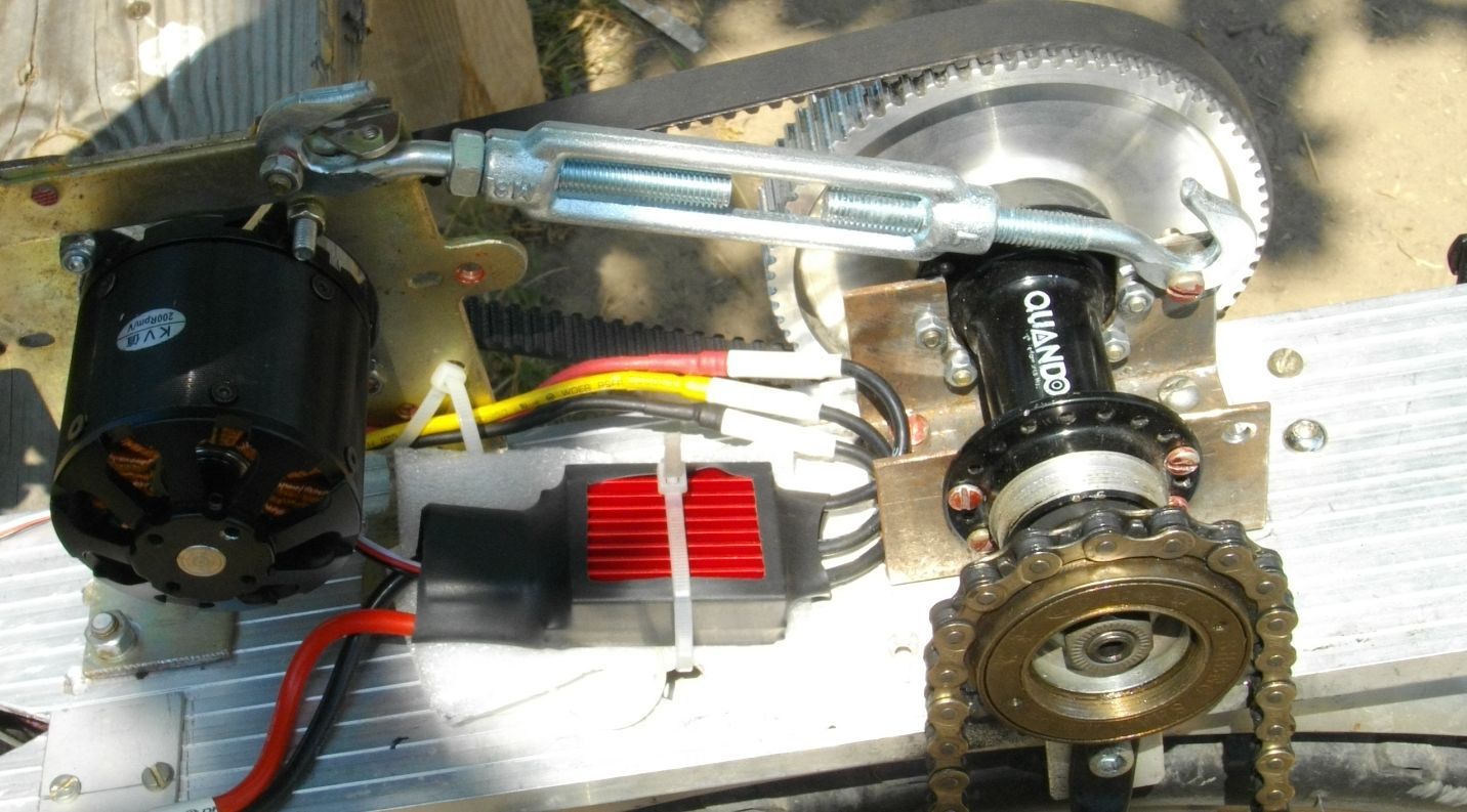
This "crutch" appeared in the process of fine-tuning the design. The engine has enough torque to deform the carrier plate, while the belt tension weakens, and it slips. Solved the problem "forehead" now everything is fine.
A variable resistor was removed in the servo tester and a hall sensor from the gas handle was connected instead.
A 1kom backwater resistor is also installed in the button circuit, since without it a mode switch was observed, apparently due to interference.
At the moment, the circuit looks like this.
In order not to pull the power wires through the entire bike, a power shunt was made by the wattmeter according to the methodology from this site .
The "+" supply and the "+" measuring are also separated, in the future I will put an isolated 5V to 9V converter (found in network cards with BNC) since in the current circuit there is still some underestimation of the current readings.
The battery is operated without BMS, to prevent overdischarge, I used a battery monitor set to 3.3 V. Upon reaching a set or lower voltage on any bank, it starts to beep very loudly.

I charge the IMAX B6 clone in Li-Io mode with balancing. Why not Li-Po? Because a charge of up to 4.1 volts instead of 4.2 should theoretically increase the battery life.
General reduction - small gear wheel 15 / large gear wheel 72 * freewill 16 / large star 50 = 0.0667
Maximum engine speeds at a nominal battery voltage of 22.2 * 200 = 4440
After reduction 4440 * 0.0667 = 293.5 rpm at wheel.
With a wheel diameter of 650 mm (let it be 640 under the load of a rider), the theoretical speed is 35.4 km / h.
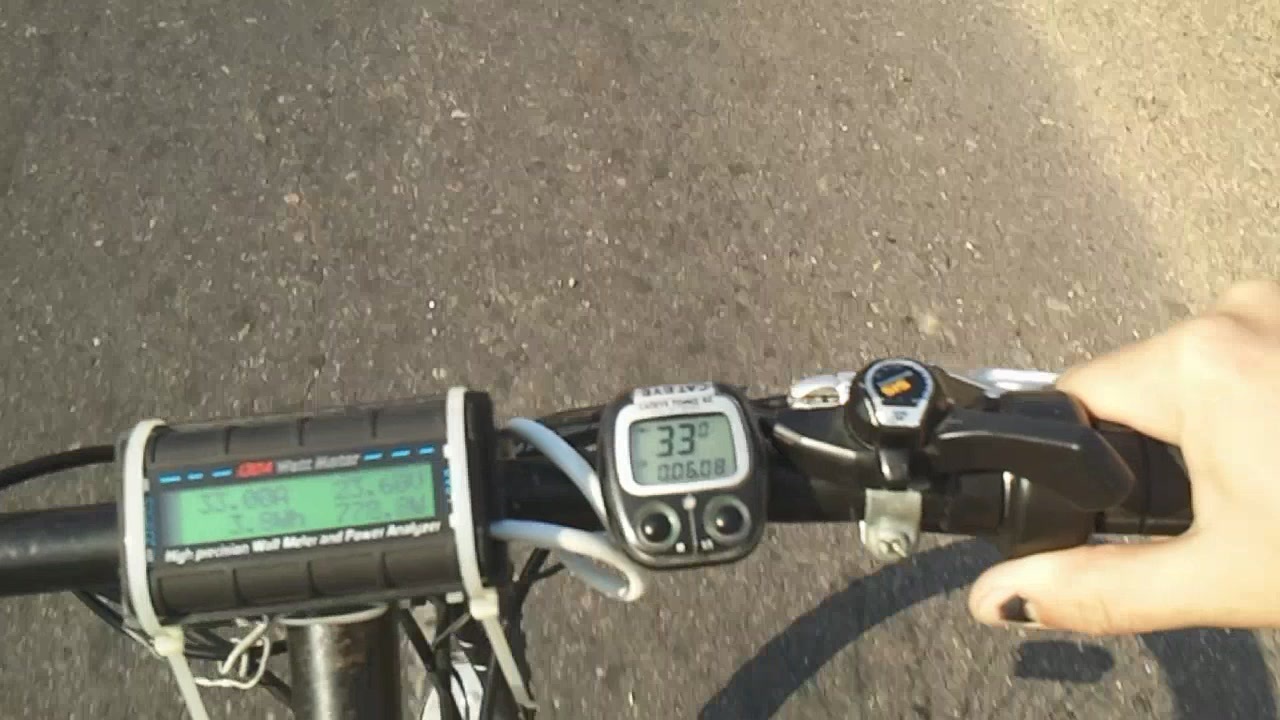
In practice, a speed of 33-34 km / h is recorded in a straight line and on slight deviations, which is close to theory.
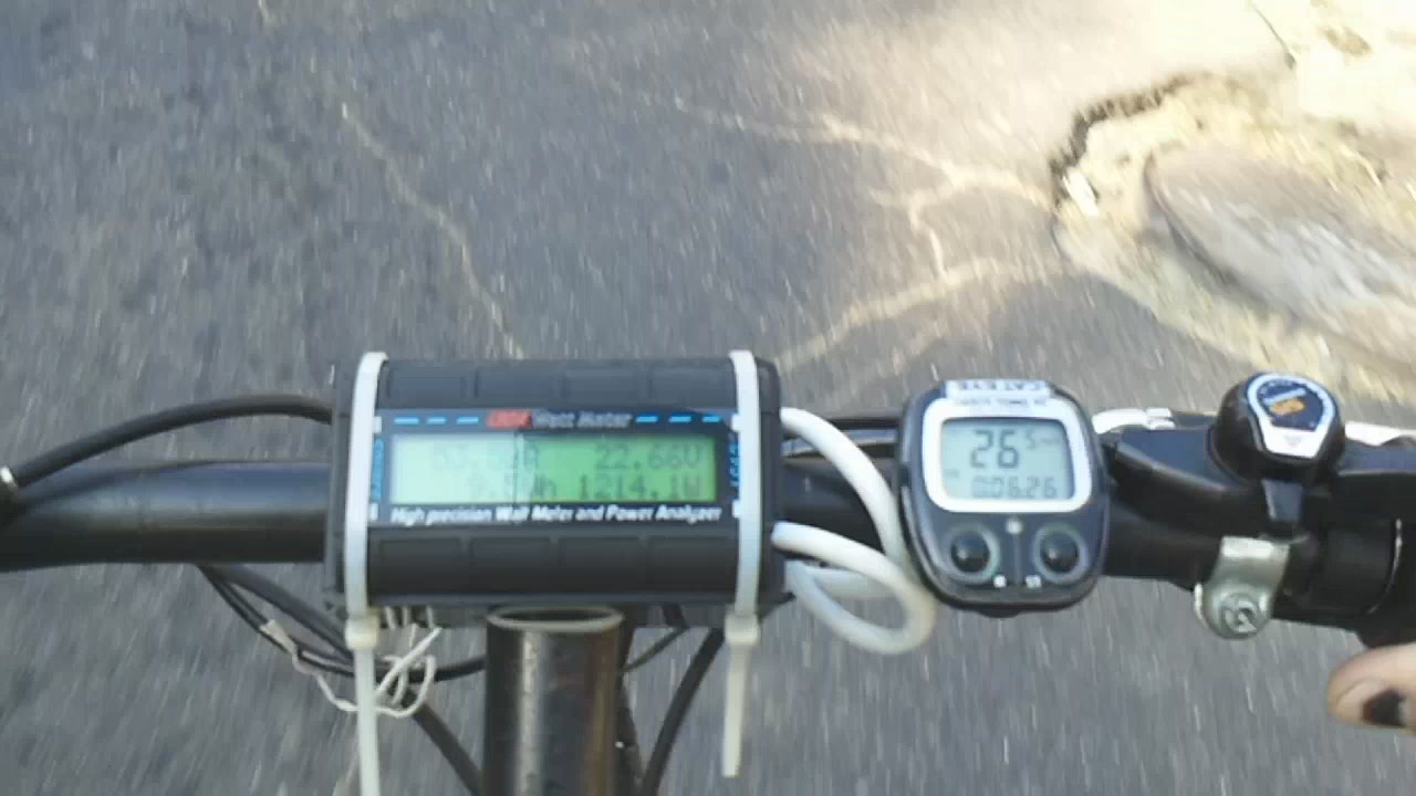
In terms of energy consumption, peak consumption (according to the readings of a wattmeter, and they can be slightly “in parrots”) is 1200 watts.
Average consumption for fast movement uphill with a slight slope of 600-800 watts. In a straight line 100-300 watts.
I tried to make a video.
Taking into account the road and shooting “on hand”, the video turned out to be so-so, but something can be considered. For the general impression, there are chopped frames - the beginning of the slide , about the 8th second of the video and the 27th , when there was a maximum current consumption. Climbing a hill without the help of legs, only on an electric motor at maximum “gas”, I don’t know the slope of the hill, for those who wish for details the route from Google maps.
Another video, the movement in a straight line, at the end a slight acceleration (in order to catch the green), the route .
In general, the concept is quite viable, the impressions of the system are positive. Fully copes with the task. Due to the sensorless engine, it naturally does not pull from the place, first we accelerate to 10-15 km / h with our feet, then smoothly give “gas”. If on the hills to help the electric drive with your feet "without straining" and maintaining a speed of about 20 km / h, it turns out to be very economical.
The plans are to increase the battery capacity, install the casing on the drive, clean up the electrical part.
The idea of recovery is still in the air, but it is very controversial.
If in my case the ratchet is removed, then due to the high reduction it will be very uncomfortable for me to ride just on the pedals. And with my modernization, I wanted to keep the ability to ride just on a bicycle, which I do on straight sections of the road. This is one of the pros, plus there will be a significant complication of the electrical part with the need to design fairly specific nodes.
And the most important point, it is not recommended to charge the battery with high currents, and the recovery just provides for just such a mode, a large current in a very short time. And this will lead to a decrease in battery life.
I want to say a big thank you to my godfather Andrei, without whom my crazy ideas would never have been embodied in metal.
Inspired by articles sponsored by chomper,
“The History of Another DIY Electric Bike ”
and “The History of Another DIY Electric Bike v2.0” , I decided to create something of my own.
What happened, so to speak, “based on”, as well as a lot of photos and text - under the cut.
I will tell the adepts of the motor wheels right away - I do not want a 7kg weight on either the front wheel or the rear. I work on the third floor and drag this charm up the stairs - no, thank you.
The concept was taken from the primary sources and rethought to fit your needs.
The motives of the construction are partially trivial - I want to ride a bicycle to work, but one slide completely kills all the impulses, and partially not - I wanted to feel my own electric bike with my own hands.
The basis was taken an outbred bike, bought many years ago from peddlers “B. at. from Europe ".
From the purchase:
Electric motor (model outrunner) size 6354 kv200
Seller Specifications
Rotational Speed: 200 (kv) RPM / V
Continuous Current: 90A
Max. Current: 100A
Input Voltage: 14.8 - 37V
Max. Efficiency: 98%
No Load Current: 0.9A
Internal Resistance: 74m (Omega)
Power: 2450W
Motor Dimensions (Diameter x Length): 63mm x 72mm
Propeller Dimensions: 19 x 10/19 x 12 / 18.5 x 12
Input Battery Types: NiCd / Nimh / Li-po Battery
Recommend Model: Airplane
Speed Controller (ESC)
In the first version was the Mystery Firedragon 80A, aka Hobbywing, aka Fentium

But with it unsatisfactory results were obtained. Disruption of synchronization under load spoiled all the pleasure of using the device.
Hobbyking SS Series 90-100A was later purchased.
With this controller, everything is much better, minor breakdowns are observed if you press the gas too sharply.

But with it unsatisfactory results were obtained. Disruption of synchronization under load spoiled all the pleasure of using the device.
Hobbyking SS Series 90-100A was later purchased.
With this controller, everything is much better, minor breakdowns are observed if you press the gas too sharply.
Servo tester
probably the simplest and most common. 
Wattmeter Clone Turnigy 130A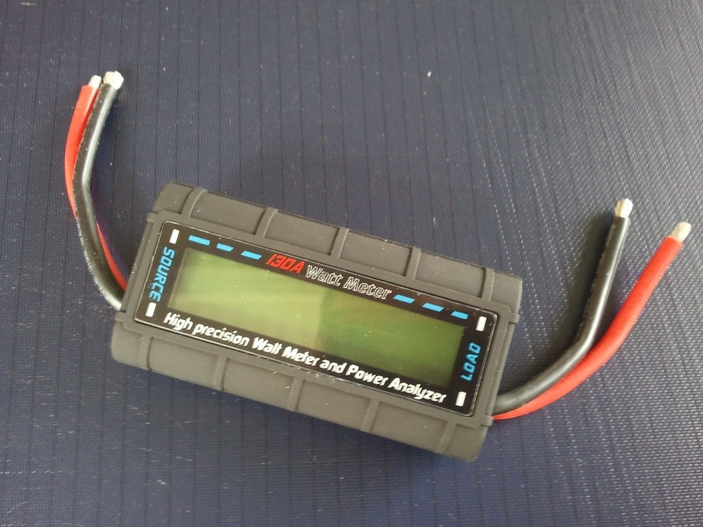
Battery - model LiPO 6S 22.2V 5a-h
Chinese brand HRB with declared current output 50C

The throttle handle from a serial electric bike, under the thumb
Inside there is a Hall sensor with linear output and a magnet system on a movable ring.
It is powered by 5 volts and produces approximately 0.7 volts to 4.6 volts.

It is powered by 5 volts and produces approximately 0.7 volts to 4.6 volts.
Brake handles with pressure sensors
I planned to cut off the gas when you press any brake, but maybe I’ll just make a stop lamp in the back

Freewill (ratchet) for 16 teeth
Rear trunk as a structural element
Finished gears and belt
With tooth profile HTD 5M for 72 and 15 teeth 15 mm wide.

- Front sprocket used 50 teeth, I don’t know from which system, I chose from what it was.
- Transfer, B. at. for use as a chain tensioner.
- The left cup of the carriage with a clamping ring (Locknut?)
- And of course the chain.
- Fasteners in stock.
I had an old rear hub.
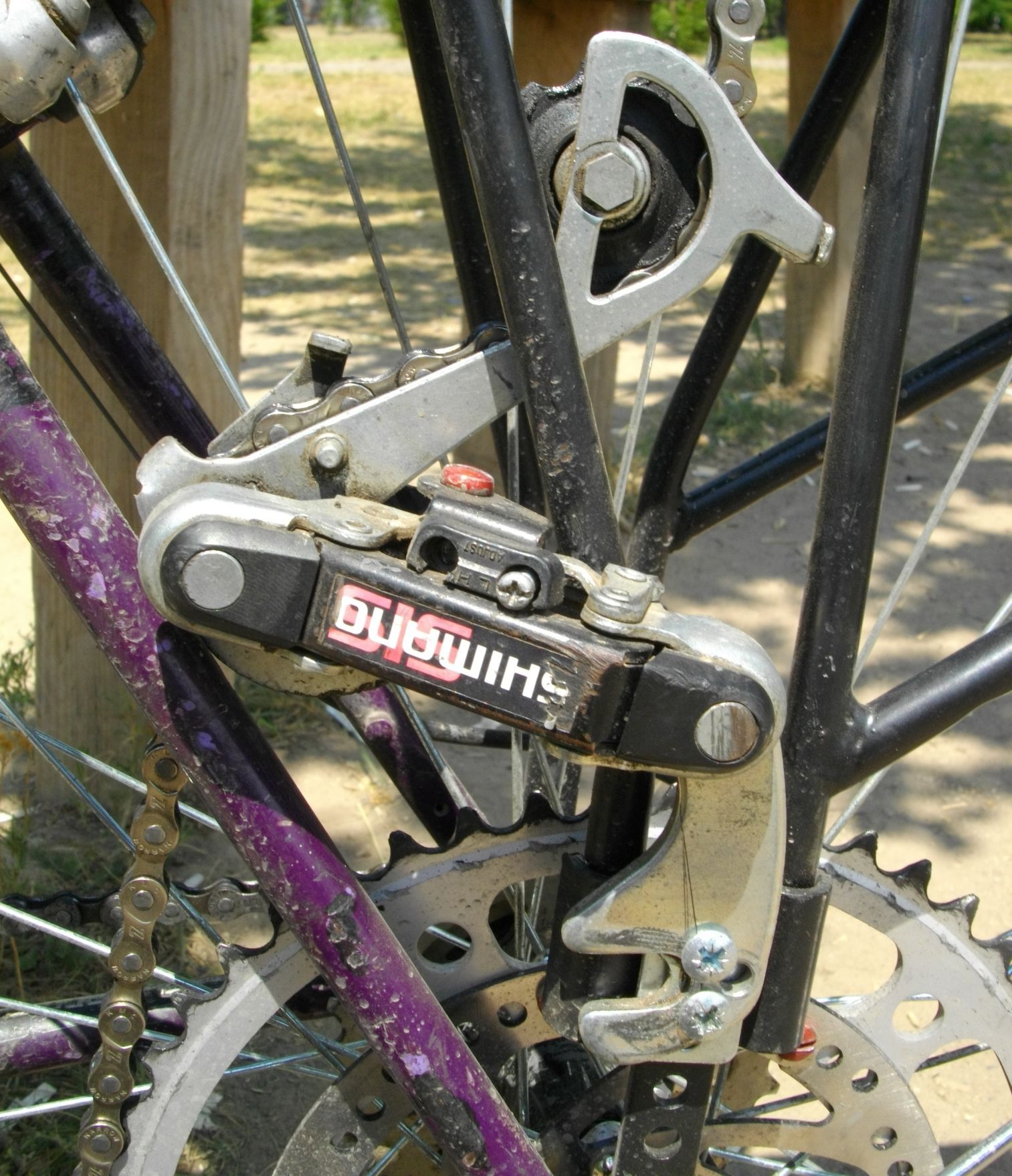
Now for the design nodes
It was decided to immediately abandon the attachment of the sprocket transmitting force to the wheel immediately.
I used a standard mount for a disk brake along with a disk. The sprocket is bolted to the disk.
I apologize for the dusty bike.
I anticipate questions about the 2 screws between the 6th disk mount - these are screws that fix the thread of the disk mount from unwinding. I agree, the decision is controversial, but it still works.
Yes, in nature there are rear hubs where the disc mount is a unit with the hub and then you would not have to use “matches and acorns”. But for certain circumstances I had to do so.
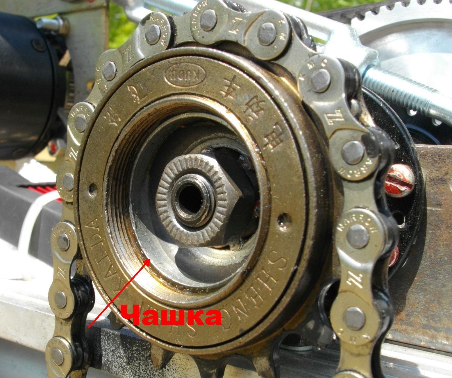
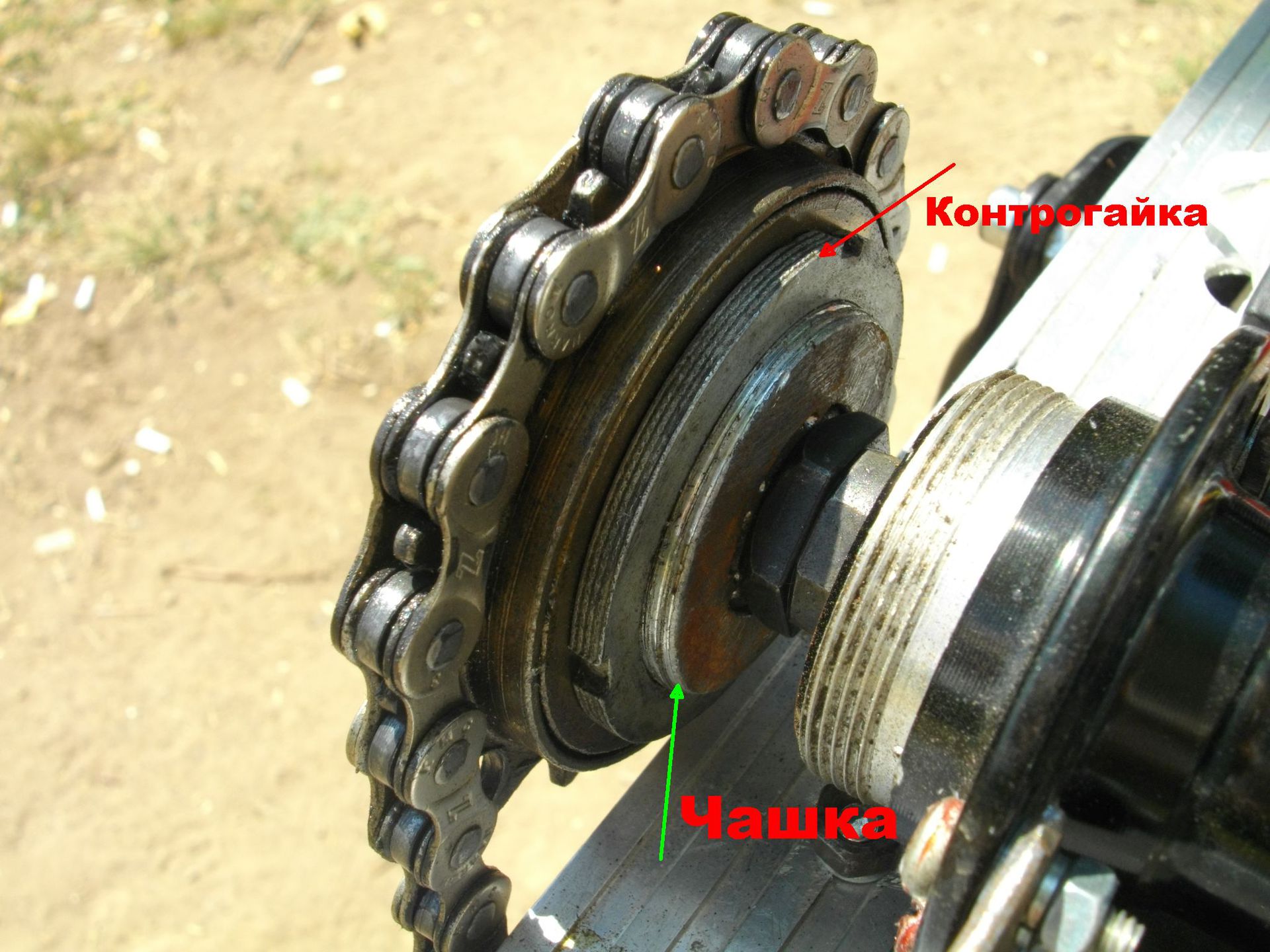
Freewill (ratchet)
Mounted on a cup from the carriage, controlled by a native ring from the cup.
The rear hub is used as an intermediate shaft
Installed in the U - shaped section of the pipe.
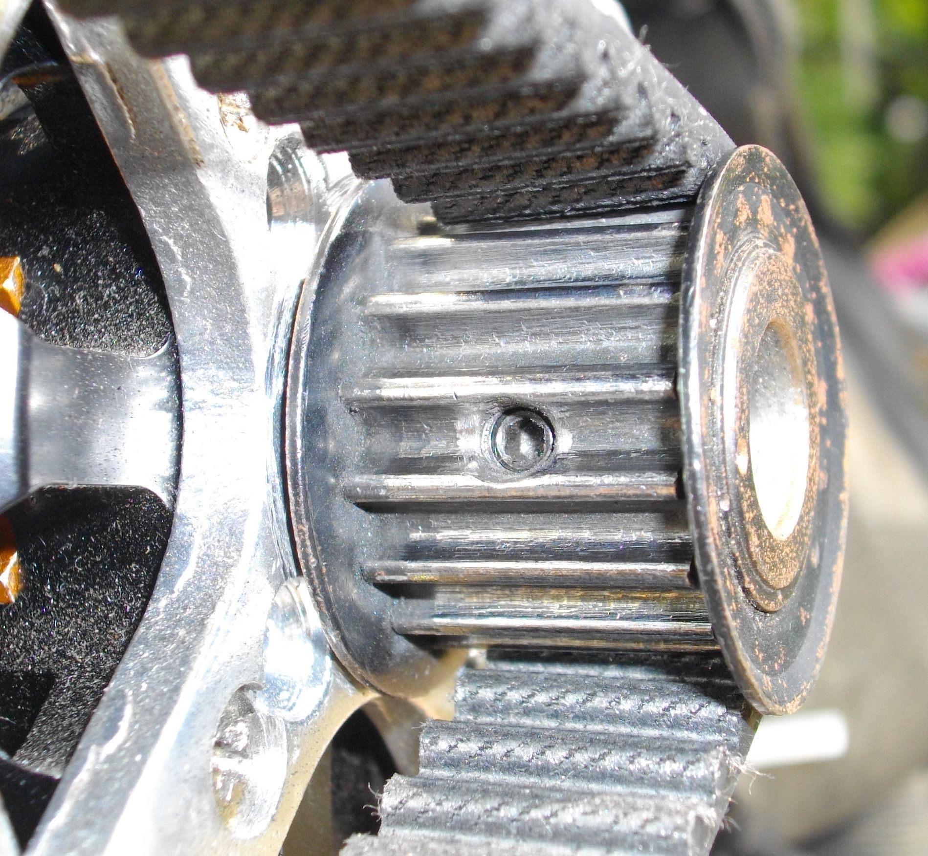
Large gear
It is fixed from turning on the shaft with a pin; without it, the sleeve “clamped” itself with cones.
A groove is milled in the gear wheel, a hole is drilled in the shaft and a pin is inserted, which fits into the groove in the wheel.
Small gear
Fixed on the motor shaft with 2 gujons.
Engine
It is fixed with a regular cross for an L-shaped structure found in bins.
Chain tensioner
Fixed on the side of the trunk.
Everything is mounted on a structured plate made of hard aluminum, which in turn is mounted on the sides of the trunk.
General form
For the most attentive
What is the lanyard for?
This "crutch" appeared in the process of fine-tuning the design. The engine has enough torque to deform the carrier plate, while the belt tension weakens, and it slips. Solved the problem "forehead" now everything is fine.
According to the electric circuit
A variable resistor was removed in the servo tester and a hall sensor from the gas handle was connected instead.
A 1kom backwater resistor is also installed in the button circuit, since without it a mode switch was observed, apparently due to interference.
At the moment, the circuit looks like this.
In order not to pull the power wires through the entire bike, a power shunt was made by the wattmeter according to the methodology from this site .
The "+" supply and the "+" measuring are also separated, in the future I will put an isolated 5V to 9V converter (found in network cards with BNC) since in the current circuit there is still some underestimation of the current readings.
The battery is operated without BMS, to prevent overdischarge, I used a battery monitor set to 3.3 V. Upon reaching a set or lower voltage on any bank, it starts to beep very loudly.
I charge the IMAX B6 clone in Li-Io mode with balancing. Why not Li-Po? Because a charge of up to 4.1 volts instead of 4.2 should theoretically increase the battery life.
What happened as a result
General reduction - small gear wheel 15 / large gear wheel 72 * freewill 16 / large star 50 = 0.0667
Maximum engine speeds at a nominal battery voltage of 22.2 * 200 = 4440
After reduction 4440 * 0.0667 = 293.5 rpm at wheel.
With a wheel diameter of 650 mm (let it be 640 under the load of a rider), the theoretical speed is 35.4 km / h.
In practice, a speed of 33-34 km / h is recorded in a straight line and on slight deviations, which is close to theory.
In terms of energy consumption, peak consumption (according to the readings of a wattmeter, and they can be slightly “in parrots”) is 1200 watts.
Average consumption for fast movement uphill with a slight slope of 600-800 watts. In a straight line 100-300 watts.
Proof
I tried to make a video.
Taking into account the road and shooting “on hand”, the video turned out to be so-so, but something can be considered. For the general impression, there are chopped frames - the beginning of the slide , about the 8th second of the video and the 27th , when there was a maximum current consumption. Climbing a hill without the help of legs, only on an electric motor at maximum “gas”, I don’t know the slope of the hill, for those who wish for details the route from Google maps.
Another video, the movement in a straight line, at the end a slight acceleration (in order to catch the green), the route .
conclusions
In general, the concept is quite viable, the impressions of the system are positive. Fully copes with the task. Due to the sensorless engine, it naturally does not pull from the place, first we accelerate to 10-15 km / h with our feet, then smoothly give “gas”. If on the hills to help the electric drive with your feet "without straining" and maintaining a speed of about 20 km / h, it turns out to be very economical.
The plans are to increase the battery capacity, install the casing on the drive, clean up the electrical part.
About recovery
The idea of recovery is still in the air, but it is very controversial.
If in my case the ratchet is removed, then due to the high reduction it will be very uncomfortable for me to ride just on the pedals. And with my modernization, I wanted to keep the ability to ride just on a bicycle, which I do on straight sections of the road. This is one of the pros, plus there will be a significant complication of the electrical part with the need to design fairly specific nodes.
And the most important point, it is not recommended to charge the battery with high currents, and the recovery just provides for just such a mode, a large current in a very short time. And this will lead to a decrease in battery life.
Acknowledgments
I want to say a big thank you to my godfather Andrei, without whom my crazy ideas would never have been embodied in metal.