CC1101 running a PIC controller or building a peer-to-peer network for a radio engineer
Prehistory
Some time ago, I participated in the design of a data collection network. The network used the 869 MHz band and the SimpliciTI protocol . In its structure, the network was essentially peer-to-peer with a central data storage node. However, the option of relaying data was also provided in the network, although it was, rather, auxiliary.
It didn’t go further than prototypes, although the matter was delivered very seriously, right up to EMC certification.
One of the reasons for the failure was that the regular programmer was not able to fully control the CC1101 .
The trick is that the SimpliciTI package taken from the Texas Instruments website already has some default settings. These settings are far from optimal for the task of rare data collection (once a month) in a network located in a house with reinforced concrete walls, and even under the influence of interference of various origins.
From the very beginning it was clear that the parameters should be, let’s say, like this, and not like that. There are a number of registers for setting parameters in the CC1101. This is all described, somewhat confused, but, in the end, after some effort is mastered.
And here is the SmartRF Studio program, the necessary parameters are set in it, checked. After a successful check, it would be necessary to transfer these parameters to real equipment. To do this, the application using SimpliciTI makes settings at the beginning of the program.
But it was not there! After a successful start, somewhere on some function from the SimpliciTI package, a rollback occurs to the parameters that were set by the developers of the package. And the programmer never found where this is happening. In particular, he was not able to run fixed-length packets and FEC. And without the latter, the operation of the system in conditions of fading signal and interference is almost impossible.
Naked CC1101 with PIC
The CC1101 has an integrated controller, so it can be controlled using a completely intelligible command system via the SPI interface.
There was an idea, but what if you take advantage of the capabilities of the CC1101 in its purest form? Of course, we were not talking about creating something like One-Net, but about some elementary tools for building a peer-to-peer network with full use of the capabilities of the CC1101 chip.
Since the standard radio engineer is for the most part far from programming controllers, the PIC platform was chosen because there is such a language as PICBASIC for these controllers .
I don’t know if C is taught today for radio engineers, but BASIC used to teach, and it’s not a question to study it. Of course, you won’t write TCP / IP on BASIC, but simple language like this is a nice way to send something to an address or receive something, and even more so, reading registers through SPI. And the whole dialogue with CC1101 is a continuous exchange of SPI with registers and nothing else!
Practical implementation
Such a board based on PIC18F2455 was assembled.
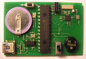
I must say that this prototype was assembled only to check the quality of communication when changing the parameters of the radio channel, so there are no interface connectors for connecting any sensors or other external devices. As can be seen in the picture, there are:
- indicator LED (2-color);
- sound emitter;
- quartz at 32768 Hz for real time clocks;
- USB interface;
- chip antenna;
- rechargeable battery from USB.
The scheme is presented here .
There is no power switch in the circuit, the antenna is shown conditionally.
This post does not provide the entire program, but it did not use absolutely all the features of CC1101.
In particular, the WOR mode was not activated. The standby mode with checking for the presence of a signal was carried out directly using the PIC18F2455 and a real-time timer.
The core of the program is, of course, SPI exchange. On the other hand, upon receipt, an interrupt to trigger processing should be triggered. The interrupt on the availability of a received packet is triggered by a signal GDO0, appropriately configured. In order not to complicate the interrupt handler, the SPI exchange is done in the polling variant based on the example presented here .
The main block of routines for controlling CC1101 via SPI looks like this:
wt_rd_reg:
'Read / write register
'
CS =% 0
pauseus 300
SSPBUF = NOW
GoSub letclear' wait for buffer to clear
a [0] = SSPBUF 'read the first byte
SSPBUF = DAT'
GoSub letclear 'wait for buffer to clear
a [1] = SSPBUF' read the second byte
CS =% 1
return
wt_rd_fifo:
'Read-write FIFO
'
SSPBUF = DAT
GoSub letclear 'wait for buffer to clear
d [i] = SSPBUF' read response byte
return
sndstrobe:
'Send control strobe to CC1101
'
CS =% 0
pauseus 300
SSPBUF = NOW
GoSub letclear 'wait for buffer to clear
a [0] = SSPBUF 'read the first byte of
pauseus 800
SSPBUF = SNOP' empty
GoSub letclear 'wait for buffer to clear
a [1] = SSPBUF' read the second byte
CS =% 1
return
letclear:
IF SSPIF = 0 Then letclear 'wait for SPI interupt flag
PauseUs 25 '25uS fudge factor
SSPIF = 0' reset flag
Here:
NOW - current command,
DAT - current data,
d [i] - array for storing data from FIFO, cannot be less than the length of FIFO,
CS - chip select.
Pauses are set experimentally. It is possible that with another controller other delays will be required or they can be significantly reduced.
For command codes, you need to look at the basic description .
The values of the registers were recorded in the EEPROM PIC18F2455, from where they were read as needed, and the address in the EEPROM corresponds to the address of the register, which allows you to easily load the desired values and always check the settings.
Practical results
After the program was written, it turned out to my great joy that ALL functions can be started, including hardware filtering, whitening, FEC, etc. etc. The packet transmission went half a kick.
The main thing is that it is clearly clear where what parameter changes, and how this happens, and what to do with it, and how to apply it. Using PICBASIC, everything is clear to a radio engineer without knowledge of the C language and special skills in writing embedded applications.
There was no purpose to lay out the program (s) completely. If this is interesting, then it can be posted, but not on this site. Actually, if it will be burningly interesting, then you can even organize something like a library.
Links used
1. CC1101, all documentation
2. SmartRF Studio
3. Microengineering Labs, company website
4. CC1101_Tester, circuit diagram
5. SPI, control in PICBASIC
6. CC1101, datasheet