How I ordered and assembled PRUSA i3
 After I got a printed case for my watch (thanks again to bigbee ), I got the idea to buy a 3D printer. I liked the idea of RepRap opensource printers, and the price of them didn’t bite. After numerous pages of forums and lots of suggestions on the Internet sites, I decided to buy Prusa i3 (Pryusha iteration 3). I ask for details under cat.
Start
Why i3? I just liked the design + a small number of printed parts + relative ease of assembly. So, with the model it was decided. Next was a search for the necessary components.
Initially, I wanted to order all the parts separately, looking for the minimum cost and optimal characteristics. With a list of parts, as well as where, how and how much to buy them, you can read here or, taking the names of the parts, find them on one of the Internet sites.
A list of what you need to purchase to build a 3D printer
Here is a rough list of what is needed to build a 3D printer.
- Frame - for i3, either aluminum or plywood. There is another option with plywood boxing.
- A set of guides and studs (smooth & threaded rods) - studs in our construction stores are also called bars. For the Z axis, M5 is mainly used, and for fasteners, the designs are M8 and M10. Guides can also be bought from us, under the name of a steel circle calibrated with a diameter of 8mm (there are options for 10mm. And 12mm.).
- Bearings (bearings) - linear under the diameter of the guides and rolling (suitable for roller skates, skateboards) for the extruder and belts.
- A set of plastic parts (Printed Parts) - are used to assemble everything together.
- Extruder (Extruder) - (printhead) consists of two parts: a plastic feeder and
ahotend (hotend) “such a metal thing” that melts plastic. For a hotend, a heating element is required (it is better to take a ceramic one) and a thermistor. - Engines (Stepper Motors) - standard NEMA-17 format. The main characteristic is the holding moment.
- Belt and pinion shaft (Belt & Belt Pulley) - the wider the belt and the smaller the tooth pitch the better.
- Coupling (Motor Coupler) - connection of motors and studs of the Z axis. Size 5 per stud diameter.
- Printed table (bed) (HeatBed) - Heated plate (mainly a printed circuit board with tracks). It is simply necessary if you are going to print ABS plastic. He needs another thermistor and the glass is not thicker than 3mm.
- Electronics here begins the fun part. There are many different control boards, but my choice fell on RAMPS, it is a shield for Arduino mega. I think lovers of arduin will like it. To RAMPS, you need:
- Stepper driver control drivers - A4988 (1/16 step mode) or DRV8825 (1/32 step mode)
- Power supply (power supply) - for RAMPS power you need 12 volts two lines 11 + 5 Amps (my power supply is 12 volts 20 amperes). You can use a computer power supply, but connect 12 volts to different lines and look at the specification of the unit for compliance with the characteristics.
- Limit switches (min / max position sensors) (EndStop) - there are three types: buttons, optical and on the effect of the hall. Usually you only need 3 sensors to determine the position of the minimum along all axes, but you can put 3 more to determine the maximum.
- Arduino mega itself or its clones.
- Any small things that you can buy in any hardware store: bolts, nuts, washers, couplers. And in the store of radio components: wires, connectors, heat shrink, electrical tape.
Here is a rough list of what is needed to build a 3D printer.
After a thorough search for products from this list, I came to the conclusion that you can buy a complete set of parts from one seller cheaper than separately, and even save on shipping. As a result, the full set cost me $ 349 + $ 97.95 for delivery.
April 11 - a set was ordered.
April 23 - departure from China.
On April 30, the parcel was lit up at customs in Moscow, and then vague doubts began to torment me. Parcel weight in the product description 8kg. and at the post office this parcel “lost weight” and began to weigh 5 kg. I decided not to raise a panic and wait for receipt.
May 6 - the parcel arrived at the place of delivery. Armed with a
After some deliberation, I went to a hardware store and bought all the guides and studs in the right quantity (but not in the right quality!) Each one meter long. As it turned out, smooth rods have a diameter of 7.86 mm instead of the declared 8 mm. Studs M8 and M5 were of good quality. For all it took 500 rubles maximum. After correspondence with the seller and an explanation of the situation (I, in broken Russian-English, in broken English-Chinese), I returned $ 40.
Guides and studs were cut with a dremel with a reinforced edged disc.

The assembly process is not very complicated and is well described on many resources, for example here , here , in great detail here, and even in Russian and with the video here .
I will write only the tool that I needed:
- wrench on 6 (M3), 8 (M5) and 13 (M8) (if you made a mistake in size - correct it), or you can use an adjustable wrench (for M8 nuts you need 2 wrenches);
- Phillips screwdriver
- hexagons for shafts and couplings;
- screwdriver;
- 5mm wood drill;
- metal drill (for plastic) 3mm., 5mm., 8mm .;
- square;
- level (optional);
- caliper (already at the calibration stage);
- pliers;
- side cutters;
- stationery knife or scalpel;
- a soldering iron and everything to it;
- fresh head;
- straight arms are
desirablejust needed.
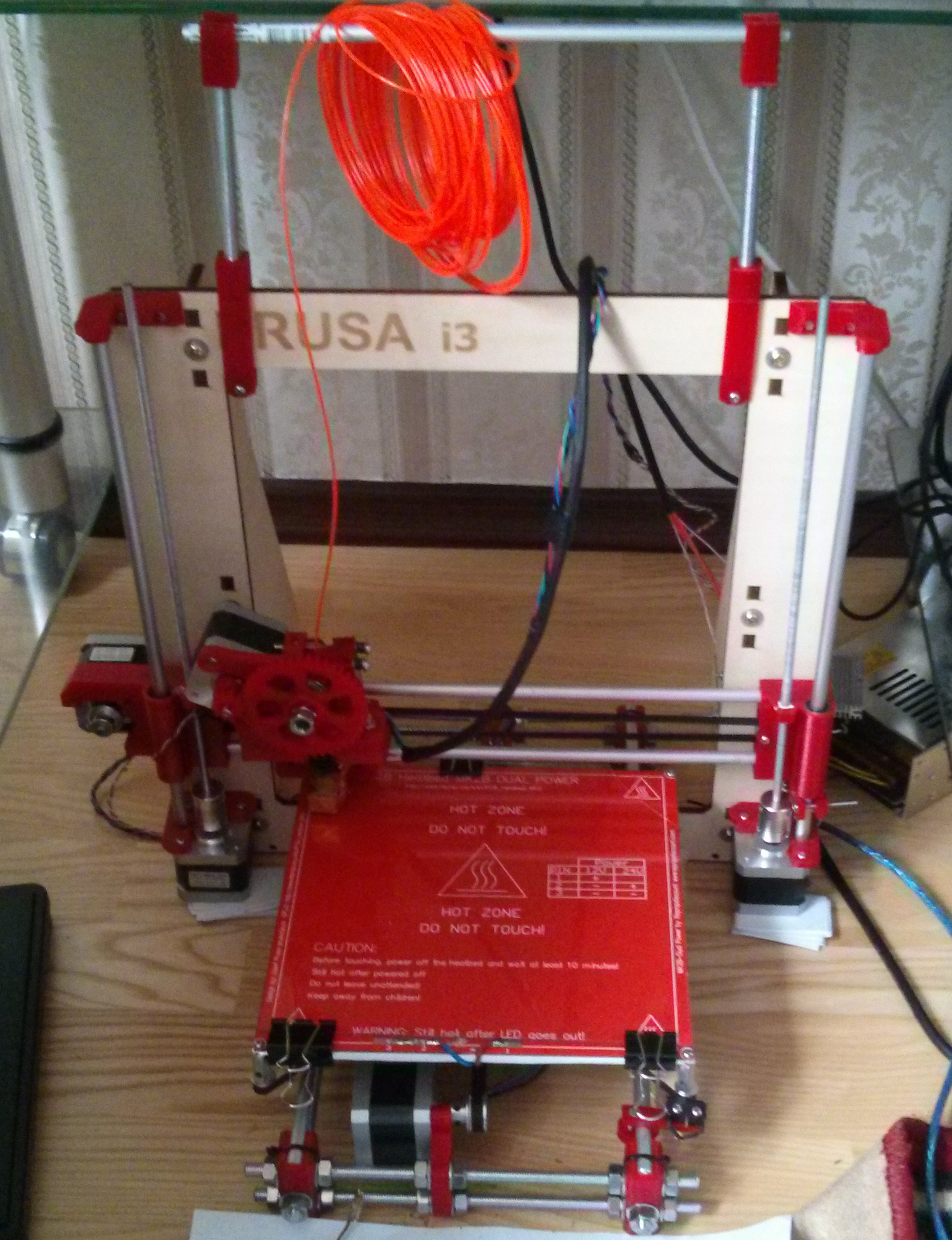
Here's what I got with the standard kit:
Advice
Below I give some tips for those who decide to assemble their printer.
I immediately put the heating table on the substrate from the "hot stand". A layer of 2mm plywood and a layer of 1mm cork, pasted over with aluminum tape in 3 layers. This was done so that the heat from the table does not go into the air.
If the holes in the plastic parts are smaller in diameter than necessary, carefully drill them in the reverse direction of the screwdriver.
If there is no groove on the stepper motors, be sure to do it! Do not count on the fact that “it is already sitting tight”, the shafts will begin to slip sooner or later.
Belts should be pulled, but not like strings.
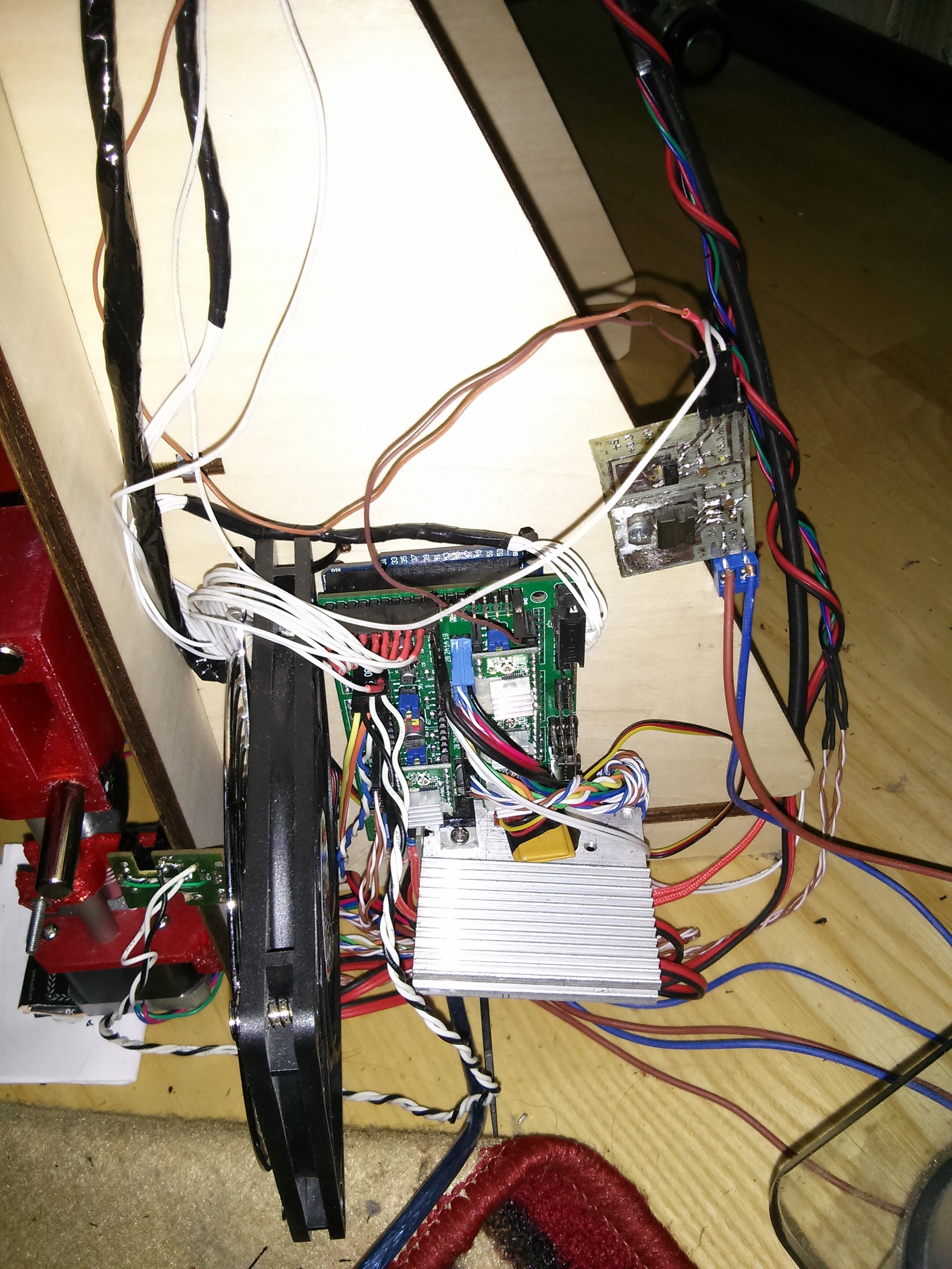
Solder, not twist wires. Collect them in bundles so that they do not interfere in the future.
Put bed power on thick wires, the cross-section should be such that when the bed is heated, the wires themselves are not heated.
Be sure to cool the drivers shagovikov and mosfet on the bed. Best radiators + cooler.
For the Z axis, it is better to use an optical endstop or Hall effect to improve positioning accuracy.
Do not save plastic. To increase the accuracy and speed of printing, it will take a lot of material.
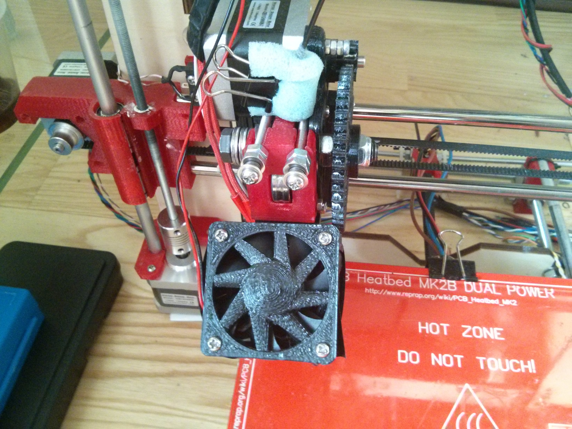
Clean the plastic at the entrance to the extruder. An ordinary sponge wrapped around a bar perfectly collects dust.
For a better plastic feed, I recommend a little groove of the pressure bearing.
Weeds
I will describe several jambs of this kit that I discovered during assembly and during operation.
The first cant I discovered: to assemble the frame, mounting holes for the nut on the M5 are provided, but the holes for the bolts are for some reason under the M4. That's why we need a 5mm wood drill.
On RAMPS there is no protection "against the fool", if you insert the stepper motor driver on the wrong side, it will burn. What happened to me (plus 1 day to search for a driver and its purchase, and minus 350 rubles).
The motor mount along the Y axis is raised too high, and the table crashes into a step. Decided to replace the mount.
The next jamb is the WADE extruder, which came in the kit, or rather, fixing it to the X axis. A hotend is inserted into the mount that connects the extruder and the X axis mount. Between the upper border of the hotend and the hole in the extruder there is a long distance in which it spirals into a stick plastic. It was decided simply by adding washers.
From the heating of the hot end, plastic began to melt: the hot end mount, the extruder body, the X axis mount. (The temporary solution was insulated with aluminum tape, and later a new extruder was printed).
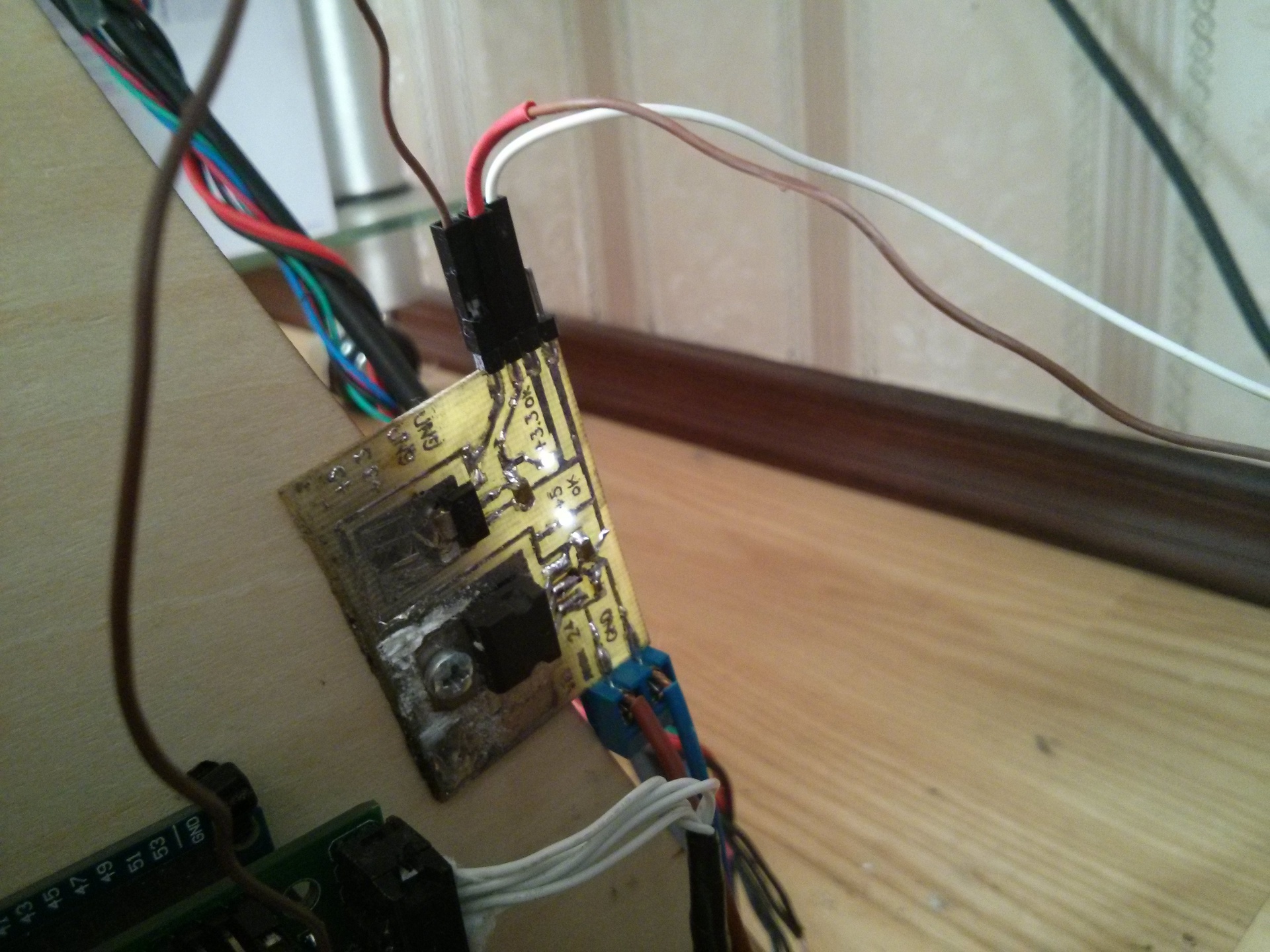
Mosfet terribly basking on the bed. The fact is that in RAMPS, mosfets controlled by 10 volts were initially supplied, but 5 volt control is coming from the arduino. Temporarily solved by installing a radiator. And for greater reliability and faster heating of the bed, there are 2 ways: change the mosfet to the desired one (for example, soldered from the motherboard) or put a relay.
Finally, a few photos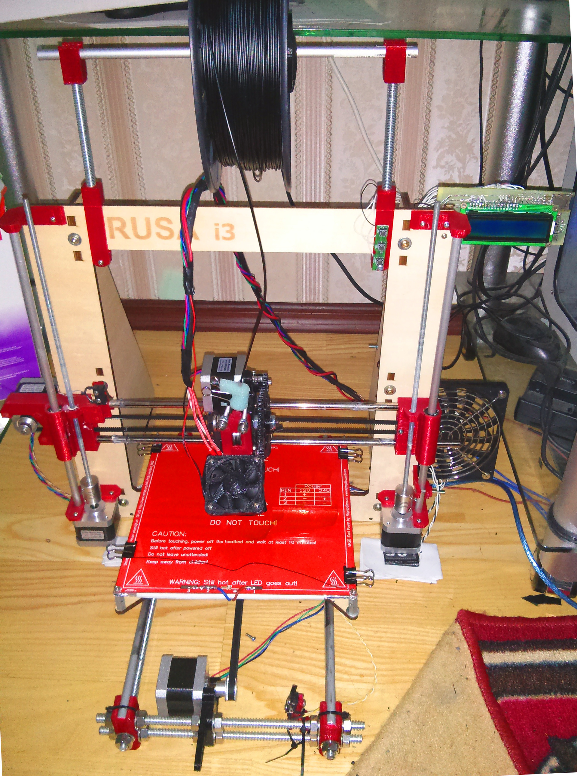


That's all for now. As usual, I look forward to questions and comments.
Well, unsubscribe in the comments about what you want to read.
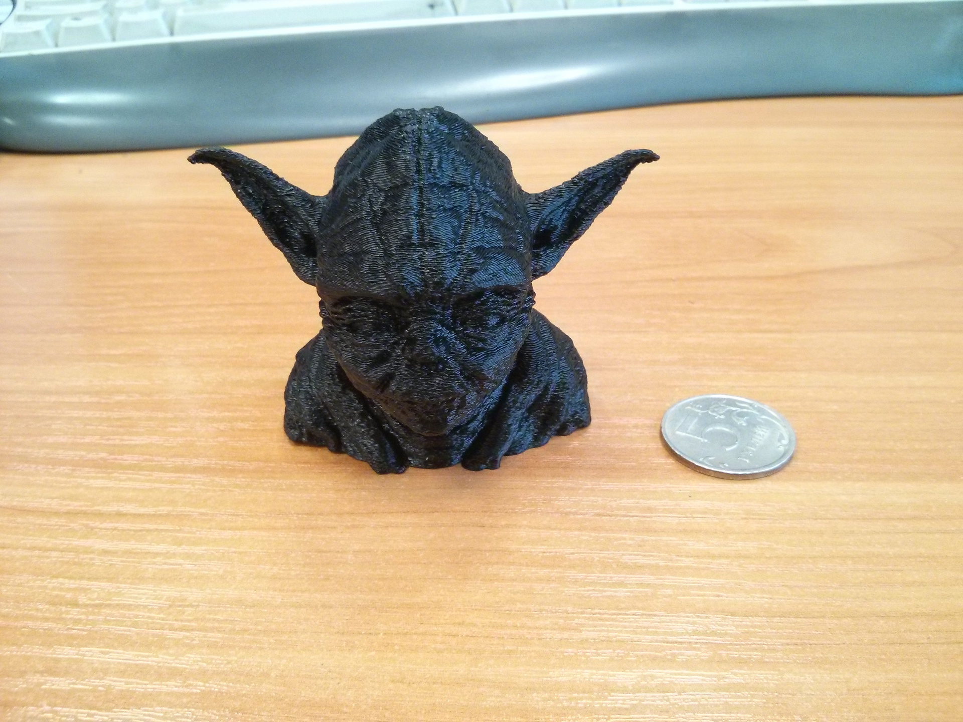
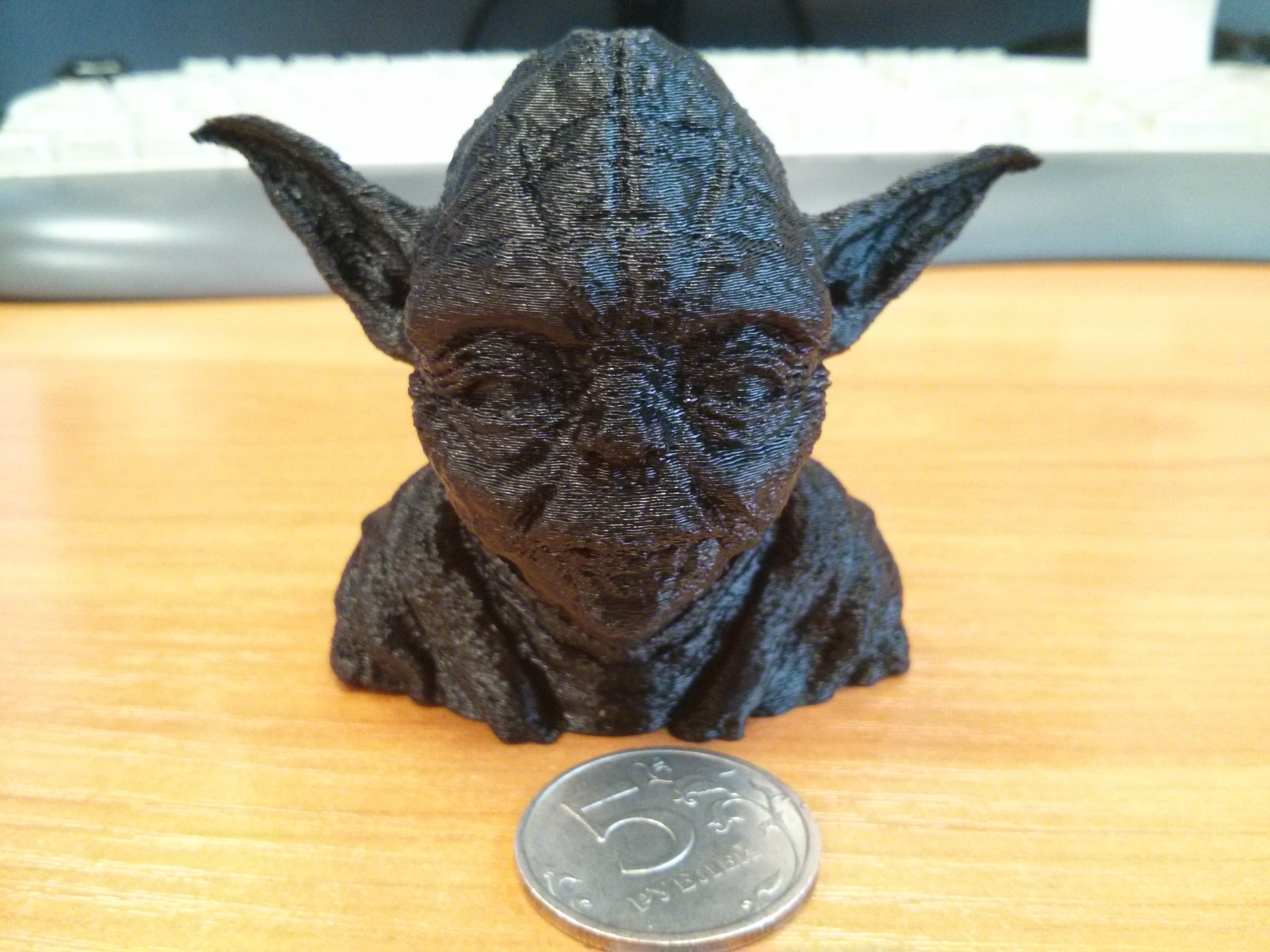
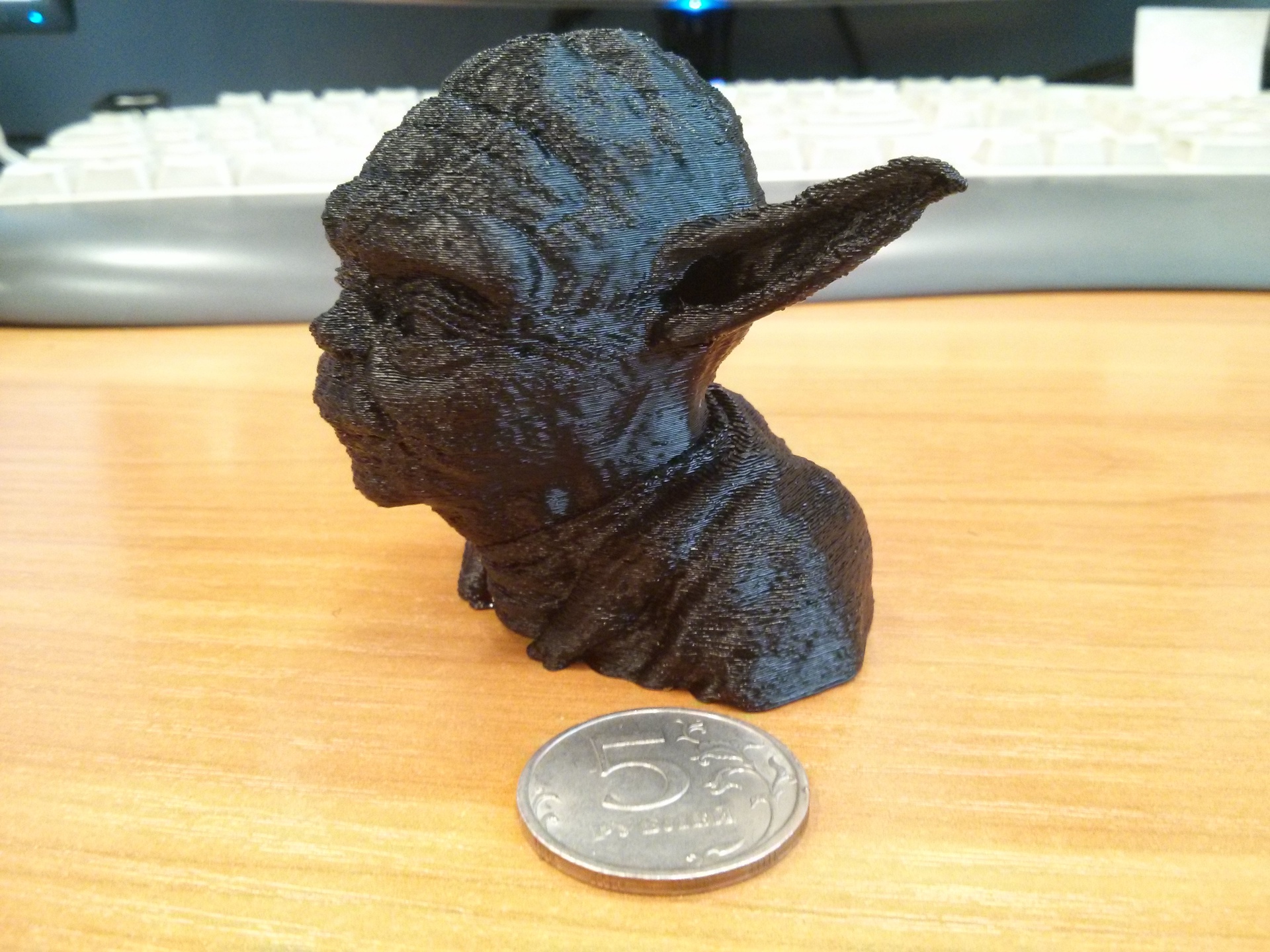
UPD: I forgot to mention that I replaced the guides on the X axis with the guides from old scanners. And yesterday, during the next trip to the hardware store, I discovered a hollow aluminum profile of 7.96 mm. (from the stated 8mi) rebuilt the axis Y and Z. That's what happened. Printing at reduced speed (30mm / s perimeter 40mm / s fill), layer height 0.2mm. Printing took 2.5 hours.
Yoda

Only registered users can participate in the survey. Please come in.
Should I continue to write articles on how I improved and improved my printer?
- 92% Yes 720
- 7.9% No 62