Sound card as a serial port
In modern PCs, there is a problem of the lack of easy-to-use interfaces. Using USB requires a large amount of complicated code, while UART requires a USB-COM adapter. If the external device is simple, then the development of the interface may take longer than the development of the device itself. At the same time, many devices have an analog interface for audio devices, which can be used to input or output data without any modification. Here is an example of data input from the STM32VLDISCOVERY board into a Windows XP PC through a microphone input. The interface is not purely digital, but digital-analog. Data from the board is transmitted in batches of 4 rectangular pulses of different amplitudes through the DAC of the controller. The pulse repetition rate corresponds to the upper frequency of the input amplifier of most sound cards - 20 kHz. The beginning of the pack is marked by a pulse of doubled width. The next 3 pulses carry information that is embedded in the amplitude of the pulse. The data transfer rate with 4-bit amplitude coding is approximately 45 kbit / s.
Code for firmware STM32VLDISCOVERY:
PC application code:
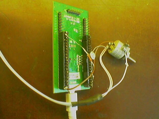
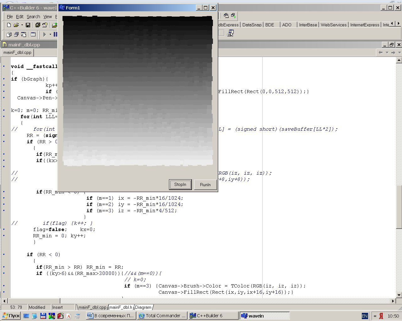
On the form there are 2 buttons “Stop” and “Run”, as well as a field of squares, the position of which on the coordinates x and y is determined by the amplitude of the first 2 pulses, and the brightness by the amplitude of the 3rd. The boards are connected by telephone wire, on the PC side there is a standard jack for mono, on the STM32VLDISCOVERY side, PA.04 output connected through an emitter follower (in the STM32VLDISCOVERY the DAC output is high resistance) and a divider for calibration (a variable resistor).
Test image transmitted to the PC via the microphone input from STM32VLDISCOVERY (32x32 square field with a gradient of squares brightness from top to bottom):
Code for firmware STM32VLDISCOVERY:
#include "stm32f10x.h"
#define DAC_DHR12RD_Address      0x40007420
#define BUF_SIZE 640
/* Init Structure definition */
DAC_InitTypeDef            DAC_InitStructure;
DMA_InitTypeDef            DMA_InitStructure;
TIM_TimeBaseInitTypeDef    TIM_TimeBaseStructure;
/* Private variables ---------------------------------------------------------*/
uint32_t DualSine12bit[BUF_SIZE], Idx = 0, Idx2 = 0, Idx3 = 0, a1,a2,a3,a4, cc;
int RR;
double R;
/* Private function prototypes -----------------------------------------------*/
void RCC_Configuration(void)
{
  /* DMA1 clock enable */
  RCC_AHBPeriphClockCmd(RCC_AHBPeriph_DMA1, ENABLE);
  /* GPIOA Periph clock enable */
  RCC_APB2PeriphClockCmd(RCC_APB2Periph_GPIOA, ENABLE);
  /* DAC Periph clock enable */
  RCC_APB1PeriphClockCmd(RCC_APB1Periph_DAC, ENABLE);
  /* TIM2 Periph clock enable */
  RCC_APB1PeriphClockCmd(RCC_APB1Periph_TIM2, ENABLE);
}
void GPIO_Configuration(void)
{
  GPIO_InitTypeDef GPIO_InitStructure;
  GPIO_InitStructure.GPIO_Pin =  GPIO_Pin_4 | GPIO_Pin_5;
  GPIO_InitStructure.GPIO_Mode = GPIO_Mode_AIN;
  GPIO_Init(GPIOA, &GPIO_InitStructure);
}
void Timebase_Configuration(void)
{
  TIM_TimeBaseStructInit(&TIM_TimeBaseStructure);
  TIM_TimeBaseStructure.TIM_Period = 0x120; //0x04;  0x150;
  TIM_TimeBaseStructure.TIM_Prescaler = 0x01;
  TIM_TimeBaseStructure.TIM_ClockDivision = 0x0;
  TIM_TimeBaseStructure.TIM_CounterMode = TIM_CounterMode_Up;
  TIM_TimeBaseInit(TIM2, &TIM_TimeBaseStructure);
	 /* TIM2 TRGO selection */
  TIM_SelectOutputTrigger(TIM2, TIM_TRGOSource_Update);
  /* TIM2 enable counter */
  TIM_Cmd(TIM2, ENABLE);
}
void DAC_Configuration()
{
	/* DAC channel1 Configuration */
  DAC_InitStructure.DAC_Trigger = DAC_Trigger_T2_TRGO;
  DAC_InitStructure.DAC_WaveGeneration = DAC_WaveGeneration_None;
  DAC_InitStructure.DAC_OutputBuffer = DAC_OutputBuffer_Disable; //Enable;
  DAC_Init(DAC_Channel_1, &DAC_InitStructure);
  /* DAC channel2 Configuration */
  DAC_Init(DAC_Channel_2, &DAC_InitStructure);
  /* Enable DAC Channel1: Once the DAC channel1 is enabled, PA.04 is
     automatically connected to the DAC converter. */
  DAC_Cmd(DAC_Channel_1, ENABLE);
  /* Enable DAC Channel2: Once the DAC channel2 is enabled, PA.05 is
     automatically connected to the DAC converter. */
  DAC_Cmd(DAC_Channel_2, ENABLE);
  /* Enable DMA for DAC Channel2 */
  DAC_DMACmd(DAC_Channel_2, ENABLE);
}
void DMA_Configuration()
{
	/* DMA1 channel4 configuration */
  DMA_DeInit(DMA1_Channel4);
  DMA_InitStructure.DMA_PeripheralBaseAddr = DAC_DHR12RD_Address;
  DMA_InitStructure.DMA_MemoryBaseAddr = (uint32_t)&DualSine12bit;
  DMA_InitStructure.DMA_DIR = DMA_DIR_PeripheralDST;
  DMA_InitStructure.DMA_BufferSize = BUF_SIZE;
  DMA_InitStructure.DMA_PeripheralInc = DMA_PeripheralInc_Disable;
  DMA_InitStructure.DMA_MemoryInc = DMA_MemoryInc_Enable;
  DMA_InitStructure.DMA_PeripheralDataSize = DMA_PeripheralDataSize_Word;
  DMA_InitStructure.DMA_MemoryDataSize = DMA_MemoryDataSize_Word;
  DMA_InitStructure.DMA_Mode = DMA_Mode_Circular;
  DMA_InitStructure.DMA_Priority = DMA_Priority_High;
  DMA_InitStructure.DMA_M2M = DMA_M2M_Disable;
  DMA_Init(DMA1_Channel4, &DMA_InitStructure);
  /* Enable DMA1 Channel4 */
  DMA_Cmd(DMA1_Channel4, ENABLE);
}
void Delay(__IO uint32_t nCount)
{
  for(; nCount != 0; nCount--);
}
void Point(uint32_t kx, uint32_t ky, uint32_t ki)
{
   for (Idx2 = 0; Idx2 < BUF_SIZE-10; Idx2++)
   {
	 DualSine12bit[Idx2+10] = DualSine12bit[Idx2];
	 }
	 DualSine12bit[0] = 4095;
	 DualSine12bit[1] = 4095;
   DualSine12bit[2] = 0;
	 DualSine12bit[3] = 0;
	 DualSine12bit[4] = 2096 + kx;
	 DualSine12bit[5] = 2000 - kx;
	 DualSine12bit[6] = 2096 + ky;
	 DualSine12bit[7] = 2000 - ky;
	 DualSine12bit[8] = 2096 + ki;
	 DualSine12bit[9] = 2000 - ki;
}
/* Private functions ---------------------------------------------------------*/
int main(void)
{
/* System Clocks Configuration */
  RCC_Configuration();
  /* Once the DAC channel is enabled, the corresponding GPIO pin is automatically
     connected to the DAC converter. In order to avoid parasitic consumption,
     the GPIO pin should be configured in analog */
  GPIO_Configuration();
  /* TIM2 Configuration */
  /* Time base configuration */
  Timebase_Configuration();
  /* DAC channel1 Configuration */
  DAC_Configuration();
  /* DMA1 channel4 configuration */
	DMA_Configuration();
R = 1; RR=1;
a1 = 2023; a2 = 1000;	a3 = 100; a4 = 900;
 while (1)
  {
  for (Idx = 0; Idx < 32*32; Idx++)
		{
		Idx3 = Idx/32;
		Point((Idx-Idx3*32)*50,Idx3*50,Idx/32*50);
		}
  }
}
PC application code:
#include
#include
#include
#include
#include
#include
#include
#include
#include
#include
#include "mainF_dbl.h"
#pragma hdrstop
#pragma package(smart_init)
#pragma resource "*.dfm"
#define INP_BUFFER_SIZE 16384
#define SAMPLE_RATE     192000
TForm1 *Form1;
static HWAVEIN hWaveIn = NULL;
static WAVEHDR WaveHdr1, WaveHdr2;
static WAVEFORMATEX waveformat ;
static unsigned short Buffer1[INP_BUFFER_SIZE], Buffer2[INP_BUFFER_SIZE], saveBuffer[INP_BUFFER_SIZE];
static signed int RR, saveBuffer2[INP_BUFFER_SIZE];
static BOOL bEnding, bGraph, flag; BOOL bShutOff;
long int RR_max, RR_min, LLL;
int ix, iy, iz, k, kx, ky, m, kp ;
void CALLBACK waveInProc1(HWAVEIN hwi, UINT uMsg, DWORD dwInstance, DWORD dwParam1, DWORD dwParam2)
{
   switch(uMsg) {
   case WIM_OPEN: break;
   case WIM_DATA: CopyMemory (saveBuffer, ((PWAVEHDR) dwParam1)->lpData, ((PWAVEHDR) dwParam1)->dwBytesRecorded) ;
    if (bEnding){ waveInReset (hWaveIn); waveInClose (hWaveIn); return; }
   waveInAddBuffer (hwi, (PWAVEHDR) dwParam1, sizeof (WAVEHDR)) ; // Send out a new buffer
   break;
   case WIM_CLOSE:
   waveInUnprepareHeader (hWaveIn, &WaveHdr1, sizeof (WAVEHDR)) ;
   waveInUnprepareHeader (hWaveIn, &WaveHdr2, sizeof (WAVEHDR)) ;
   }
}
//xxxxxxxxxxxxxxxxxxxxxxxxxxxxxxxxxxxxxxxxxxxxxxxxxxxxxxx
void __fastcall TForm1::startButtonClick(TObject *Sender)
{
bGraph=false;
}
//xxxxxxxxxxxxxxxxxxxxxxxxxxxxxxxxxxxxxxxxxxxxxxxxxxxxxxx
void __fastcall TForm1::formDestroy(TObject *Sender)
{
   bEnding=false;
}
//xxxxxxxxxxxxxxxxxxxxxxxxxxxxxxxxxxxxxxxxxxxxxxxxxxxxxxx
void __fastcall TForm1::Button1Click(TObject *Sender)
{
  bGraph=true;
}
//xxxxxxxxxxxxxxxxxxxxxxxxxxxxxxxxxxxxxxxxxxxxxxxxxxxxxxx
__fastcall TForm1::TForm1(TComponent* Owner)
   : TForm(Owner)
{
   waveformat.wFormatTag      = WAVE_FORMAT_PCM ;
   waveformat.nChannels       = 1; //2 ;
   waveformat.wBitsPerSample  = 16 ;
   waveformat.nSamplesPerSec  = SAMPLE_RATE ;
   waveformat.nBlockAlign     = waveformat.nChannels * (waveformat.wBitsPerSample / 8);
   waveformat.nAvgBytesPerSec = waveformat.nBlockAlign * waveformat.nSamplesPerSec;
   waveformat.cbSize          = 0 ;
   if (waveInOpen (&hWaveIn, WAVE_MAPPER, &waveformat, (DWORD)waveInProc1, 0, CALLBACK_FUNCTION)){
      Application->MessageBox( "000000000","Error",MB_OK );
      return;
   }
   bShutOff=false;
// Set up headers and prepare them
   WaveHdr1.lpData          = (BYTE *)Buffer1 ;
   WaveHdr1.dwBufferLength  = INP_BUFFER_SIZE*2 ;    //
   WaveHdr1.dwBytesRecorded = 0 ;
   WaveHdr1.dwUser          = 0 ;
   WaveHdr1.dwFlags         = 0 ;
   WaveHdr1.dwLoops         = 1 ;
   WaveHdr1.lpNext          = NULL ;
   WaveHdr1.reserved        = 0 ;
   waveInPrepareHeader (hWaveIn, &WaveHdr1, sizeof (WAVEHDR)) ;
   WaveHdr2.lpData          = (BYTE *)Buffer2 ;
   WaveHdr2.dwBufferLength  = INP_BUFFER_SIZE*2 ;    //
   WaveHdr2.dwBytesRecorded = 0 ;
   WaveHdr2.dwUser          = 0 ;
   WaveHdr2.dwFlags         = 0 ;
   WaveHdr2.dwLoops         = 1 ;
   WaveHdr2.lpNext          = NULL ;
   WaveHdr2.reserved        = 0 ;
   waveInPrepareHeader (hWaveIn, &WaveHdr2, sizeof (WAVEHDR)) ;
   waveInAddBuffer (hWaveIn, &WaveHdr1, sizeof (WAVEHDR)) ;
   waveInAddBuffer (hWaveIn, &WaveHdr2, sizeof (WAVEHDR)) ;
   waveInStart (hWaveIn) ;
   bGraph=true; bEnding = FALSE;
}
void __fastcall TForm1::Timer1Timer(TObject *Sender)
{
if (bGraph){
           kp++;
           if (kp>20){kp=0; Canvas->Brush->Color = Color; Canvas->FillRect(Rect(0,0,512,512));}
k=0; m=0; RR_min=0; RR_max=0; kx=0; ky=0;
   for(int LLL=0; LLL 0)
       {
        if(RR_max < RR) RR_max = RR;
        if((kx>6)&&(RR_min<30000))      { //&&(k==0)){
                                  m=0;
                                  }
        if(RR_min < 0) {
                        if (m==1) ix = -RR_min*16/1024;
                        if (m==2) iy = -RR_min*16/1024;
                        if (m==3) iz = -RR_min*4/512;
                       }
       flag=false;    kx=0;
       RR_min = 0; ky++;
       }
     if (RR < 0)
       {
        if(RR_min > RR) RR_min = RR;
        if (ky>6){
                      if (m==3) {Canvas->Brush->Color = TColor(RGB(iz, iz, iz));
                      Canvas->FillRect(Rect(ix,iy,ix+16,iy+16));}
                       }
       if(!flag) m++;
       RR_max = 0;
       flag=true;  ky=0;
       kx++;
       }
    }
  }
}
On the form there are 2 buttons “Stop” and “Run”, as well as a field of squares, the position of which on the coordinates x and y is determined by the amplitude of the first 2 pulses, and the brightness by the amplitude of the 3rd. The boards are connected by telephone wire, on the PC side there is a standard jack for mono, on the STM32VLDISCOVERY side, PA.04 output connected through an emitter follower (in the STM32VLDISCOVERY the DAC output is high resistance) and a divider for calibration (a variable resistor).

Test image transmitted to the PC via the microphone input from STM32VLDISCOVERY (32x32 square field with a gradient of squares brightness from top to bottom):
