May 19, 2014 at 17:27
Mini CRT Monitor
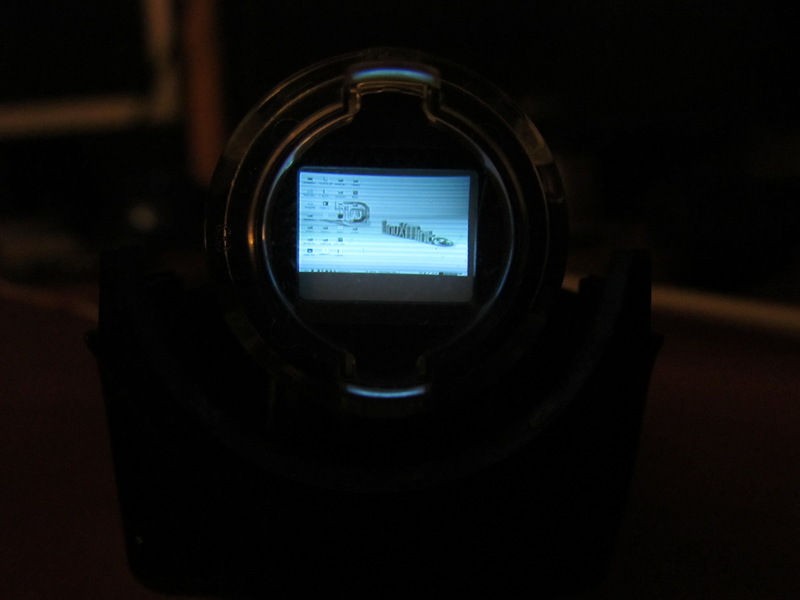
At night I could not sleep from the spring of spleen, and in order to escape from sad thoughts, I began to come up with various inventions. And he came up with how to make a miniature CRT monitor. CRT - because I basically love the lamp technique, and even more so the information display device. To begin with, I will show the result.
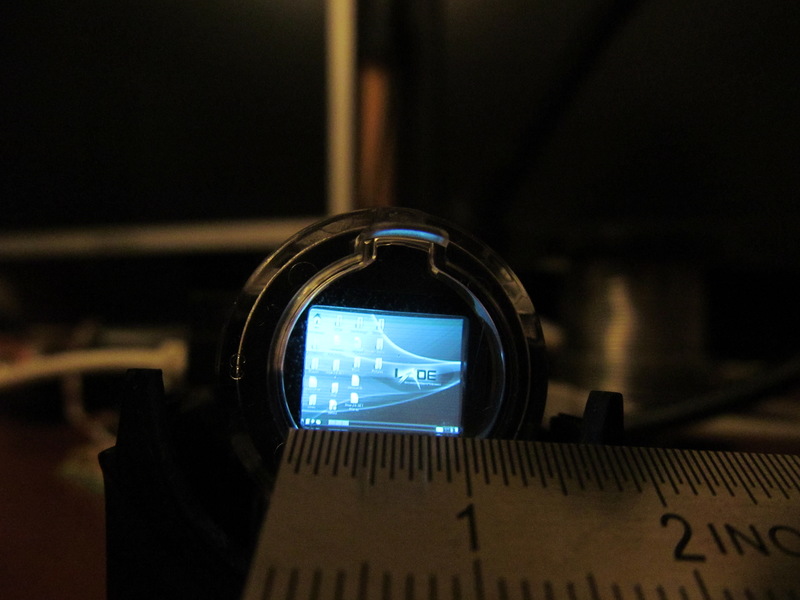
Warm tube Debian lxde
Miniature CRT monitor measuring only 1 cm! And to do this is very simple and everyone can! Go!
In fact, the essence of the idea is simple. In old VHS cassette camcorders, an ordinary small picture tube acts as the viewfinder display. And once upon a time in the journal “Radio” I saw an article on how to make a television out of this picture tube. And then at night I thought: if you can make a TV, then you can make a monitor!
Of course, I decided to google it. At the request of “Viewfinder Hack” there is a lot of interesting things, I will leave you this information to be torn apart. But I found one website www.ccs.neu.edu/home/bchafy/tiny/tinyterminal.html , where a friend is trying different ways to display information, and just one of the ideas is to use a picture tube from an old video camera.
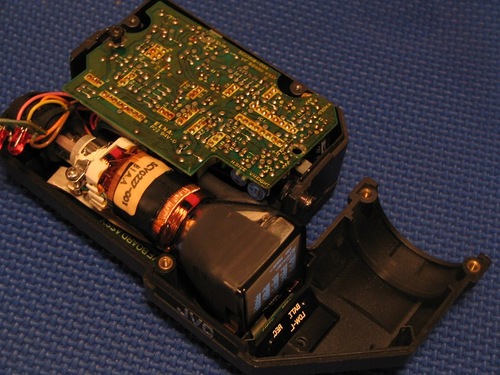
Viewfinder from the camera.
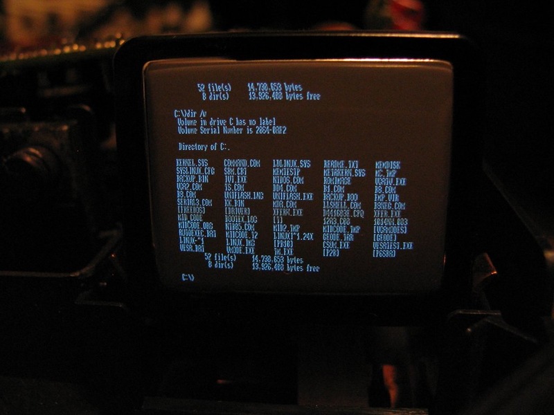
Warm tube dos.
These pictures are taken from this site. You apparently were also intrigued, how to do this?
The idea is very simple and trivial. In the old days there was no such development of small LCD displays, much less color ones, and then the lamp ruled. In the viewfinder of the old cameras is a CRT ( Electron Beam Tube)), and interestingly, it is fed (in the sense of a tube circuit) with a small and affordable 5 V voltage in the household (you can take it, for example, from USB). Current consumption is also small. The most delicious thing is that only a composite video signal is needed for the input to this screen . We have a composite video signal from a VCR, DVD player, cameras, almost every camera, Nokia N900, Nokia N9 phones (I can’t say for others, I don’t know), some video cards. The most interesting thing is that a composite video signal can even be obtained from a VGA-video card using a fairly simple circuit

. VGA-to-video converter circuit
As you can see, there are huge opportunities for creativity. Now we need to understand how to do all this.
To make such a miniature display, we need an old VHS-camcorder, straight arms, and one 75 Ohm resistor (optional). Plus a good mood, a soldering iron, a multimeter, free time and desire.
As for the camera, I want to say that cameras that have a color image in the viewfinder will not work for us right away. You can immediately sweep cameras that have a side screen. The older the camera, the better. The most relish - cameras with an angular viewfinder or professional cameras. They usually have a fairly large display.
The instructions below are not universal! You may have to turn on the brain, look for documentation, poke devices at different nodes, but it can go the same way as mine.
I want to note that in the viewfinder there can only be a picture tube, and the “brains” can be in the main body, but I was lucky.
So, you managed to get a video camera. Failed? Blow on avity, slanda, hammers, ebay, flea markets, there is this good in bulk for a penny! We will assume that you still got it. My good LJ friend gave me the camera. He immediately understood the chip and presented me the Panasonic NV-S600EN .
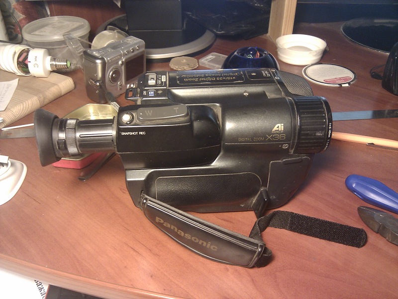
Camera before experiments
The camera was without a battery, without a power supply, and it was generally not known whether it worked. First, I took it apart. I can’t give universal instructions: what can be unscrewed is unscrewed, all the curtains open, all the screws are unscrewed. It makes sense to start parsing from the side opposite the cassette. In this way, my camera was divided into two halves, in the second there was a patch scarf with a viewfinder, and in the other a camera about steel giblets. He took off the scarf from the second half, the viewfinder, and removed a piece of plastic altogether. While the camera should not be disassembled completely, tk. we still need its performance.
I put the patch board back into its native socket.
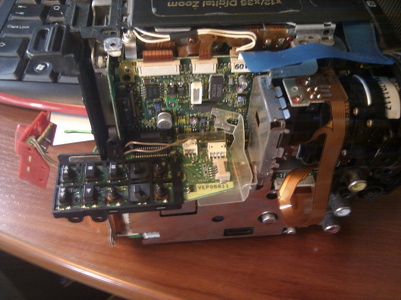
Patch board
The viewfinder, after disconnecting, was horrifying at me: ten (!) Wires came out of it. Seven color and three gray, but after disassembling, it turned out that 7 color went to the buttons located on the viewfinder (zoom). Safely take out these buttons. We get such a parsley:
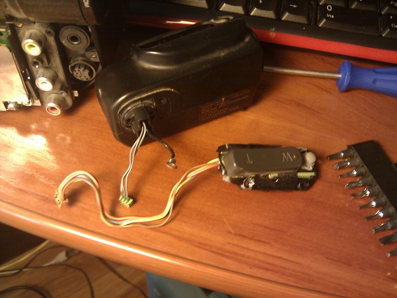
Viewfinder, with three gray wires, one black ground wire and a number of zoom buttons near The
viewfinder is interesting to look inside. I will not describe its device, I think you can find the description yourself if you wish.
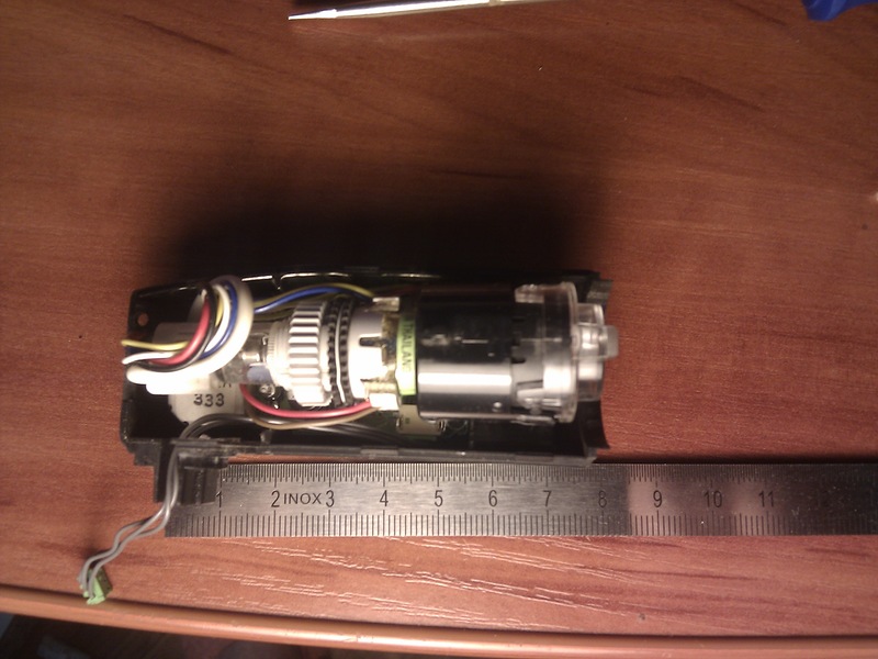
With the lid open, a top view
I removed the “eye” myself as unnecessary, although I use it occasionally. The screen itself reminds us of old black and white televisions, which the modern generation has not even seen.
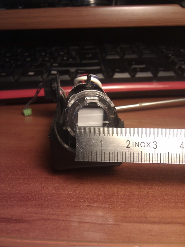
Miniature screen
Three wires going to the display, as you probably guessed, we will have: a common wire, +5 volts and the composite video signal itself. It remains to determine who we have.
Paraphrasing the famous dictum, we will move on. Our task now is to solve the rebus of three gray wires: who, where, why and why. The simplest thing is to find a common wire. I did not have a battery, but its contacts stuck out. We take the multimeter in the dialing mode, touch the minus of these contacts at one end (I have signed), and the other look at the contacts of our three wires through the connector. On one rang - it means a common wire.
It should be noted that, hypothetically, battery power can be decoupled, in this case you need to watch the common wire according to the scheme inside the camera, usually all screens and wide polygons “ring” with it.
Now collect the camera back! Those. not completely assembled, and so that all electrical components work. It looked like this to me
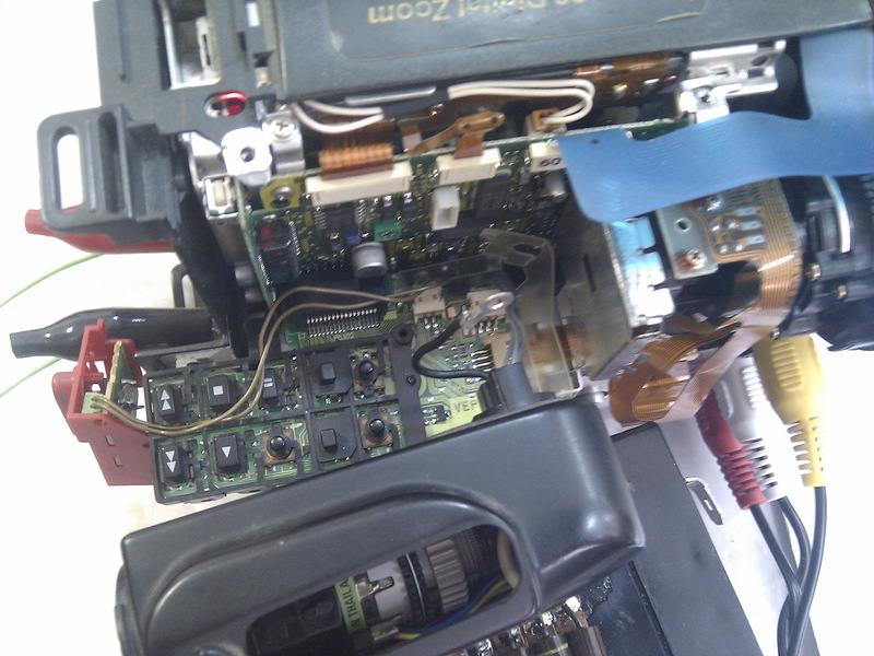
Electrically assembled camera
To determine the other two signals, the camera had to be powered up. Since the camera was orphaned, I powered from an industrial power supply, which we connected directly to the contacts for the battery. The camera agreed to work normally, only with power settings 6V, 6A. Prior to this, at the start, she blinked an LED, a screen, jumped the engine and was cut down. I suppose that all electrolytes have dried out there. After we brought the current to such astronomical sizes, it still wound up and did not hang.
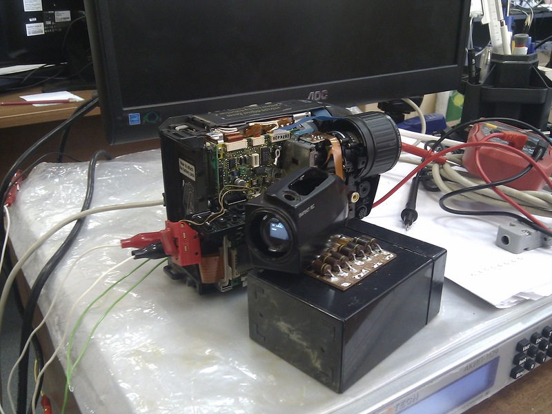
A working camera
I could not deny myself the pleasure of checking the operability of the camera and the display itself, so I hooked up a TV to the camera, and all sorts of inscriptions looked on the screen.

My nickname is
The screen image did not work well in the photo, but I can assure you - it is impeccable!
Okay, pamper, make sure that everything works and further on the road. Now we need to find out where we have food. We put the multimeter into the constant voltage measurement mode, we hook one contact to the common wire, and the other poke into the remaining two wires. If on one wire the power is somewhere between 1.5-1.7 V, then this is most likely a video signal. The other wire will have approximately 5 V (it should be understood that there may be 4.8 V, as in my case). As a result, we draw everything on a piece of paper, and we get such a connection scheme.
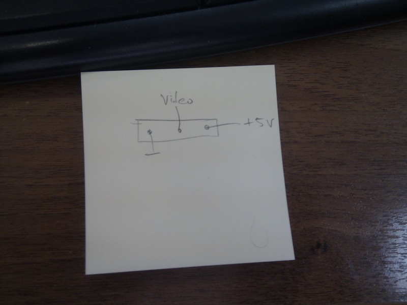
Connection diagram
After all this, we disassemble the entire structure, and begin assembling a new one.
Since the power of the display was 5 V, it was decided to power it from USB. I want to upset some who hope that there will be 5V everywhere. After reading similar guides for the manufacture of products from displays, I came to the conclusion that the power of the display is not necessarily 5 V! Maybe 6, and 12. So be careful!
But in my case, everything is fine. Solder the USB cable and power it on from charging.
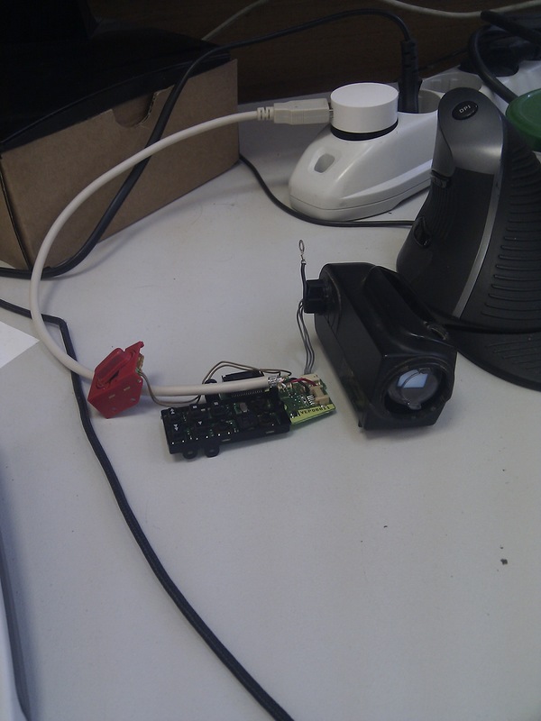
Wool on the screen
On the screen you should see a familiar coat.
I draw your attention to the fact that despite the meager currents there is a high-voltage transformer there! And climb your hands into the phone is not worth it, otherwise it will be bo-bo !!! As a precaution, I hide everything in the case before turning it on.
After a successful start, it is worth checking the input impedance of the line. On the disconnected display, we measure the resistance between the common wires and the view input wire. If it is equal to 75 Ohms - calm down and skip this operation. In my case it was 1kOhm. To match the line, you must solder a 75 Ohm resistor between the common wire and the signal wire. In principle, the operation is not critical, but my video card and some other video outputs refused to show without agreed resistance. Of course, it is better to solder the resistor as close as possible, but I did everything on the patch board.
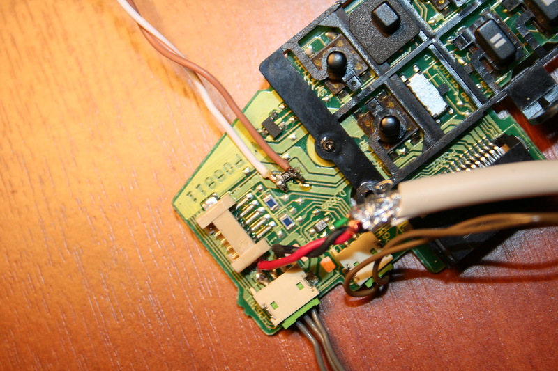
Resistor 75 Ohm, frame size 0805
I didn’t have a tulip-mother connector on hand, so I found a SCART connector in my trash can, disassembled it and soldered to the scarf inside. As a video source I used my Nokia N9 with debian on board.
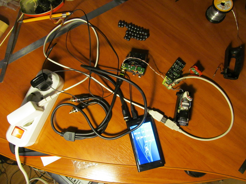
The assembly is complete, everything is clear, I do not deceive you.
Everything works right after connection. I do not have a native cable for Nokia, and I used a store cable for 200 rubles. Everything started up immediately.

Desktop on a micromonitor
Frankly, it was very difficult to take this and the photo at the beginning of the post, I spent an hour experimenting with light, shutter speed, aperture, etc. But the result is perfect. Live it is even better! It's still a lot of fun watching a video from such a screen.
It's not so simple with a computer. There are several solutions to the problem. One of them is to buy a VGA to S-VIDEO adapter, it’s worth a mere penny, another option is to solder yourself, I gave the circuit above. The third option is to use video cards with S-VIDEO output, for example, these:
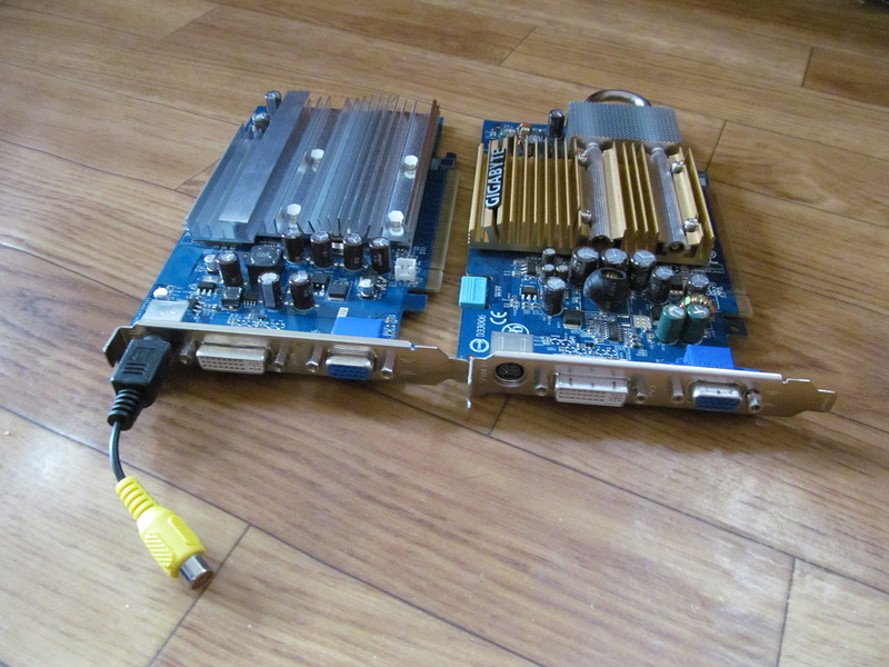
Found
video cards on the mezzanine. The video card has a round connector, similar to ps / 2. Need an appropriate adapter, comes with a video card. In the photo, it hangs on the left. Since I did not plan to replace my video card with this old stuff, so I just tried how it would look.
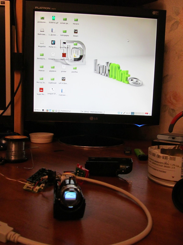
My desktop on a large computer
It is duplicated on a micromonitor
The attentive reader will notice that some fields have appeared. The change of permissions (of all) did not affect their availability in any way. Understand the reasons for their appearance there is no sense, no desire. The fact that this works is installed, we return the video card to its place.
In conclusion, I want to say that this craft does not have practical meaning or I do not see it. The display has sufficient resolution to even read texts on it, but it is so small that you cannot make out anything on it without an optical system.
It is possible that if it were possible to connect it as a third monitor, it would be possible to display some useful information there, but again I do not know why.
So, in essence, this is fun entertainment that can be demonstrated to your children, friends and girlfriends. It looks impressive when you take your phone, insert a wire and an image is displayed on the screen :).
From these viewfinders, people make night vision devices. For example, here is
1. www.doityourselfgadgets.com/2012/04/night-vision.html(English)
2. tnn-hobby.ru/proekt-vyihodnogo-dnya/kak-videt-v-temnote.html (Russian)
Well, some people make a wearable display:
rc-aviation.ru/forum/topic?id= 1283
You can make virtual reality glasses if you wish, but I have little idea how to separate the video signal without a lot of hemorrhoids. So all this is entertainment and no more.
Thanks to comrade freeman for the camera and my wife for patience :).
Warm tube Debian lxde
Miniature CRT monitor measuring only 1 cm! And to do this is very simple and everyone can! Go!
From the idea ...
In fact, the essence of the idea is simple. In old VHS cassette camcorders, an ordinary small picture tube acts as the viewfinder display. And once upon a time in the journal “Radio” I saw an article on how to make a television out of this picture tube. And then at night I thought: if you can make a TV, then you can make a monitor!
Remember: if you came up with a cool idea - google! Surely she came to someone else!
Of course, I decided to google it. At the request of “Viewfinder Hack” there is a lot of interesting things, I will leave you this information to be torn apart. But I found one website www.ccs.neu.edu/home/bchafy/tiny/tinyterminal.html , where a friend is trying different ways to display information, and just one of the ideas is to use a picture tube from an old video camera.
Viewfinder from the camera.
Warm tube dos.
These pictures are taken from this site. You apparently were also intrigued, how to do this?
The idea is very simple and trivial. In the old days there was no such development of small LCD displays, much less color ones, and then the lamp ruled. In the viewfinder of the old cameras is a CRT ( Electron Beam Tube)), and interestingly, it is fed (in the sense of a tube circuit) with a small and affordable 5 V voltage in the household (you can take it, for example, from USB). Current consumption is also small. The most delicious thing is that only a composite video signal is needed for the input to this screen . We have a composite video signal from a VCR, DVD player, cameras, almost every camera, Nokia N900, Nokia N9 phones (I can’t say for others, I don’t know), some video cards. The most interesting thing is that a composite video signal can even be obtained from a VGA-video card using a fairly simple circuit
. VGA-to-video converter circuit
As you can see, there are huge opportunities for creativity. Now we need to understand how to do all this.
What to do and who is to blame?
To make such a miniature display, we need an old VHS-camcorder, straight arms, and one 75 Ohm resistor (optional). Plus a good mood, a soldering iron, a multimeter, free time and desire.
As for the camera, I want to say that cameras that have a color image in the viewfinder will not work for us right away. You can immediately sweep cameras that have a side screen. The older the camera, the better. The most relish - cameras with an angular viewfinder or professional cameras. They usually have a fairly large display.
The instructions below are not universal! You may have to turn on the brain, look for documentation, poke devices at different nodes, but it can go the same way as mine.
I want to note that in the viewfinder there can only be a picture tube, and the “brains” can be in the main body, but I was lucky.
So, you managed to get a video camera. Failed? Blow on avity, slanda, hammers, ebay, flea markets, there is this good in bulk for a penny! We will assume that you still got it. My good LJ friend gave me the camera. He immediately understood the chip and presented me the Panasonic NV-S600EN .
Camera before experiments
The camera was without a battery, without a power supply, and it was generally not known whether it worked. First, I took it apart. I can’t give universal instructions: what can be unscrewed is unscrewed, all the curtains open, all the screws are unscrewed. It makes sense to start parsing from the side opposite the cassette. In this way, my camera was divided into two halves, in the second there was a patch scarf with a viewfinder, and in the other a camera about steel giblets. He took off the scarf from the second half, the viewfinder, and removed a piece of plastic altogether. While the camera should not be disassembled completely, tk. we still need its performance.
I put the patch board back into its native socket.
Patch board
The viewfinder, after disconnecting, was horrifying at me: ten (!) Wires came out of it. Seven color and three gray, but after disassembling, it turned out that 7 color went to the buttons located on the viewfinder (zoom). Safely take out these buttons. We get such a parsley:
Viewfinder, with three gray wires, one black ground wire and a number of zoom buttons near The
viewfinder is interesting to look inside. I will not describe its device, I think you can find the description yourself if you wish.
With the lid open, a top view
I removed the “eye” myself as unnecessary, although I use it occasionally. The screen itself reminds us of old black and white televisions, which the modern generation has not even seen.
Miniature screen
Three wires going to the display, as you probably guessed, we will have: a common wire, +5 volts and the composite video signal itself. It remains to determine who we have.
Hacking is an interest, plus electrifying all devices
Paraphrasing the famous dictum, we will move on. Our task now is to solve the rebus of three gray wires: who, where, why and why. The simplest thing is to find a common wire. I did not have a battery, but its contacts stuck out. We take the multimeter in the dialing mode, touch the minus of these contacts at one end (I have signed), and the other look at the contacts of our three wires through the connector. On one rang - it means a common wire.
It should be noted that, hypothetically, battery power can be decoupled, in this case you need to watch the common wire according to the scheme inside the camera, usually all screens and wide polygons “ring” with it.
Now collect the camera back! Those. not completely assembled, and so that all electrical components work. It looked like this to me
Electrically assembled camera
To determine the other two signals, the camera had to be powered up. Since the camera was orphaned, I powered from an industrial power supply, which we connected directly to the contacts for the battery. The camera agreed to work normally, only with power settings 6V, 6A. Prior to this, at the start, she blinked an LED, a screen, jumped the engine and was cut down. I suppose that all electrolytes have dried out there. After we brought the current to such astronomical sizes, it still wound up and did not hang.
A working camera
I could not deny myself the pleasure of checking the operability of the camera and the display itself, so I hooked up a TV to the camera, and all sorts of inscriptions looked on the screen.
My nickname is
The screen image did not work well in the photo, but I can assure you - it is impeccable!
Okay, pamper, make sure that everything works and further on the road. Now we need to find out where we have food. We put the multimeter into the constant voltage measurement mode, we hook one contact to the common wire, and the other poke into the remaining two wires. If on one wire the power is somewhere between 1.5-1.7 V, then this is most likely a video signal. The other wire will have approximately 5 V (it should be understood that there may be 4.8 V, as in my case). As a result, we draw everything on a piece of paper, and we get such a connection scheme.
Connection diagram
After all this, we disassemble the entire structure, and begin assembling a new one.
New life of the old display
Since the power of the display was 5 V, it was decided to power it from USB. I want to upset some who hope that there will be 5V everywhere. After reading similar guides for the manufacture of products from displays, I came to the conclusion that the power of the display is not necessarily 5 V! Maybe 6, and 12. So be careful!
But in my case, everything is fine. Solder the USB cable and power it on from charging.
Wool on the screen
On the screen you should see a familiar coat.
I draw your attention to the fact that despite the meager currents there is a high-voltage transformer there! And climb your hands into the phone is not worth it, otherwise it will be bo-bo !!! As a precaution, I hide everything in the case before turning it on.
After a successful start, it is worth checking the input impedance of the line. On the disconnected display, we measure the resistance between the common wires and the view input wire. If it is equal to 75 Ohms - calm down and skip this operation. In my case it was 1kOhm. To match the line, you must solder a 75 Ohm resistor between the common wire and the signal wire. In principle, the operation is not critical, but my video card and some other video outputs refused to show without agreed resistance. Of course, it is better to solder the resistor as close as possible, but I did everything on the patch board.
Resistor 75 Ohm, frame size 0805
I didn’t have a tulip-mother connector on hand, so I found a SCART connector in my trash can, disassembled it and soldered to the scarf inside. As a video source I used my Nokia N9 with debian on board.
The assembly is complete, everything is clear, I do not deceive you.
Everything works right after connection. I do not have a native cable for Nokia, and I used a store cable for 200 rubles. Everything started up immediately.
Desktop on a micromonitor
Frankly, it was very difficult to take this and the photo at the beginning of the post, I spent an hour experimenting with light, shutter speed, aperture, etc. But the result is perfect. Live it is even better! It's still a lot of fun watching a video from such a screen.
What about a computer?
It's not so simple with a computer. There are several solutions to the problem. One of them is to buy a VGA to S-VIDEO adapter, it’s worth a mere penny, another option is to solder yourself, I gave the circuit above. The third option is to use video cards with S-VIDEO output, for example, these:
Found
video cards on the mezzanine. The video card has a round connector, similar to ps / 2. Need an appropriate adapter, comes with a video card. In the photo, it hangs on the left. Since I did not plan to replace my video card with this old stuff, so I just tried how it would look.
My desktop on a large computer
It is duplicated on a micromonitor
The attentive reader will notice that some fields have appeared. The change of permissions (of all) did not affect their availability in any way. Understand the reasons for their appearance there is no sense, no desire. The fact that this works is installed, we return the video card to its place.
Hello. My last name is “Total”
In conclusion, I want to say that this craft does not have practical meaning or I do not see it. The display has sufficient resolution to even read texts on it, but it is so small that you cannot make out anything on it without an optical system.
It is possible that if it were possible to connect it as a third monitor, it would be possible to display some useful information there, but again I do not know why.
So, in essence, this is fun entertainment that can be demonstrated to your children, friends and girlfriends. It looks impressive when you take your phone, insert a wire and an image is displayed on the screen :).
From these viewfinders, people make night vision devices. For example, here is
1. www.doityourselfgadgets.com/2012/04/night-vision.html(English)
2. tnn-hobby.ru/proekt-vyihodnogo-dnya/kak-videt-v-temnote.html (Russian)
Well, some people make a wearable display:
rc-aviation.ru/forum/topic?id= 1283
You can make virtual reality glasses if you wish, but I have little idea how to separate the video signal without a lot of hemorrhoids. So all this is entertainment and no more.
Thanks to comrade
freeman for the camera and my wife for patience :).