April 13, 2014 at 04:19
Reduce the number of wires in Arduino - I2C LCD screen and RTC clock on two wires
I recently met Arduino, so many of my examples seem simple.
However, for newcomers like me, this information will be useful and save a lot of time.
I2C is the standard for communicating devices on 2 wires, while the number of devices that hangs in parallel on these wires can be very large. Each device has its own address at which the device is accessed. Addressing can be changed if the device has jumpers with which you can set an additional offset relative to the base address that is hard-coded in the device.
It is in a nutshell.
I started with the fact that I bought a 16x2 character LCD display in Ibei. By connecting as standard - I realized that this is not what is needed. A lot of wires - takes a bunch of legs, chaos and disorder.
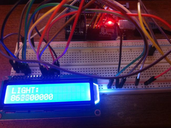
Googled, I realized that there are displays with interfaces that simplify the connection. googled yet, found an adapter on I2C for my LCD. A month of waiting, hooray, hooked up.
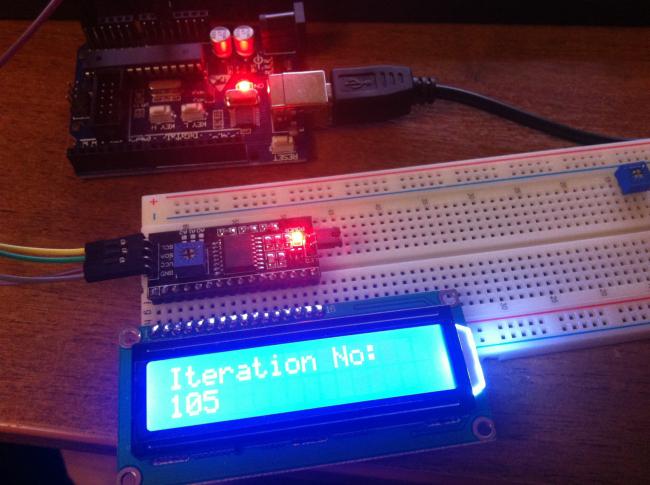
It looks much more interesting!
The problem arose during the search for working libraries and examples. As it turned out later - in the main most famous library bitbucket.org/fmalpartida/new-liquidcrystal/downloads - examples are not working! It took some time and effort =)
Specifically, here are working examples and a link to the library. arduino-info.wikispaces.com/LCD-Blue-I2C
There you can also find descriptions of the various versions of LCD-I2C adapters that you can buy.
I bought this one www.ebay.com/itm/310565362720 it is assembled on a PCF8574 chip
This version of the library requires setting display parameters as follows
where the first number is the address of the device, the rest are assigned control pins of the adapter for a specific display. here the problem was hidden - many examples initialize the screen with incorrect data - while the screen blinks, twitches and does not work.
The correct line, with the address and the necessary pins, depends on the particular display. It’s difficult for a beginner to understand the essence and score the necessary data!
All of the above is a working option. It is probably even better than the library that I am currently using. But it seemed to me too redundant and bulky.
The second library started working immediately. arduino-info.wikispaces.com/file/detail/LiquidCrystal_I2C1602V1.zip/341635514
Unfortunately, I don’t remember where I got the demo for this library, but it uses a simplified LCD setup, which I needed and needed.
In this line, the device address is assigned and the type of display is determined, 16 characters in 2 lines.
The first and second libraries are not compatible with each other! . Examples for one library do not work with another. The following code will refer to the last specified library for working with I2C LCD.
After connecting the screen, I wanted to display something on it. Just the numbers are not interesting. Let there be hours =)) Probably, everyone goes this way, including me. The Arduino software clock allows itself to show the time, but the problem is data reset during shutdown. And since I don’t have any buttons, I have to set the clock through the cable via the COM port through the console. In general, it bothered me very quickly.
Real-time clock RTC1307 is probably the most common watch chip. There are many pluses - a separate microcircuit, independent of the main Arduino power supply with a battery, independent of the main program - time counts for sure! The advantage of watches based on 1307 - I2C. At the same time, you do not need to use any additional outputs - everything is controlled via the same 2 wires as the LCD.
The library for working with I2c watches worked right away, examples are working. github.com/adafruit/RTClib
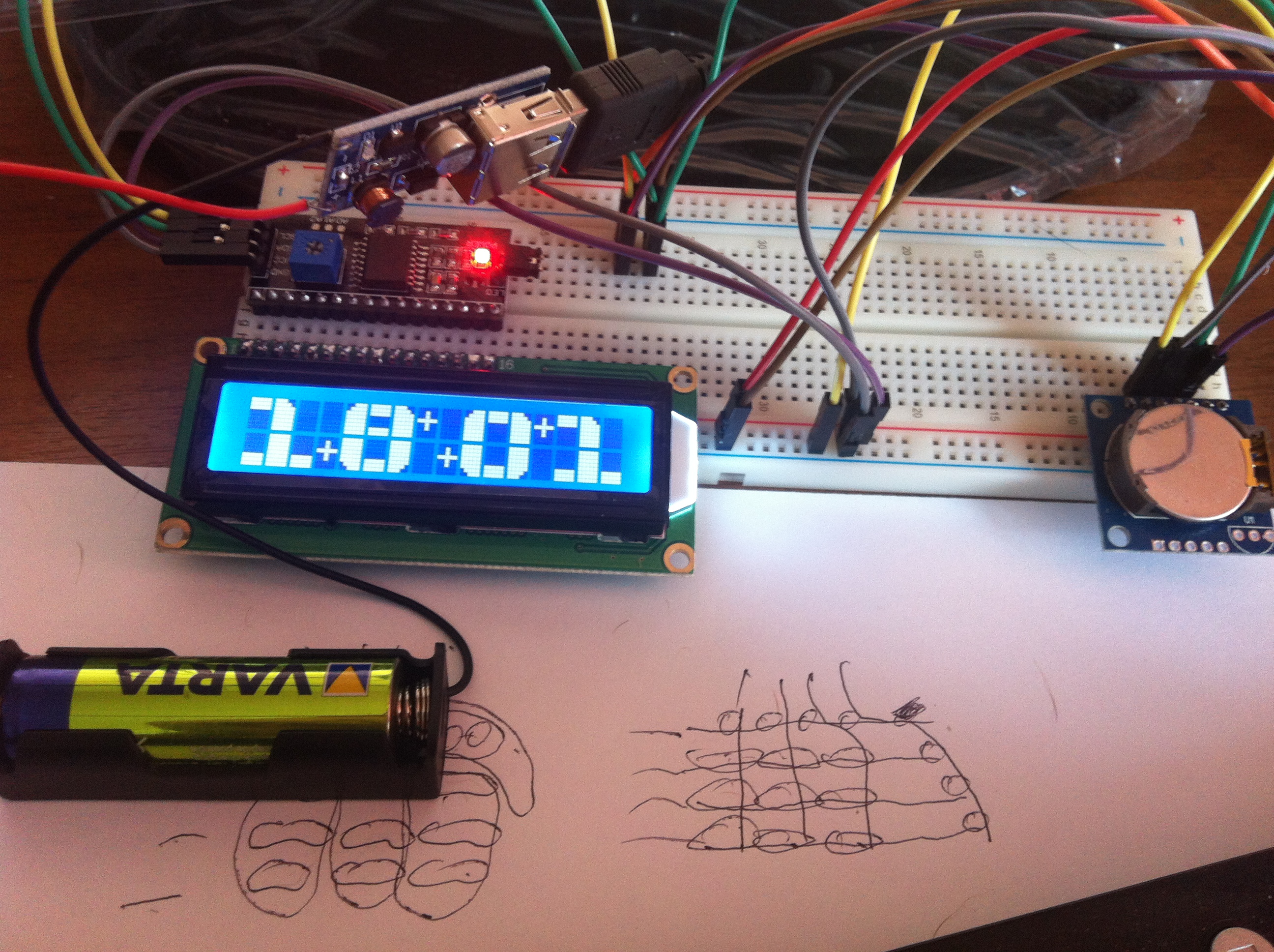
The program is simple, everything is transparent. Numbers are created by functions in which a number is displayed in separate blocks. Blocks of 5x8 points are set in user characters, there can be a maximum of 8. Examples are taken from the arduino.cc forum.
Drawing takes place in a separate function, the numbers are displayed one at a time. Running crosses - a whim of the author, i.e. mine)) The offset of the numbers is controlled when the draw function is called.
I would be grateful to experienced programmers if they tell me how to make the code more compact. It seems that there are many opportunities for optimizing the same type of data, but I don’t know how to implement it. I saw examples on the same forum arduino.cc - but did not understand the essence of what was happening - the code is poorly commented out and I do not understand where the legs grow from. Something there was connected with the memory of the LCD controller / I would be grateful for commenting on the code.
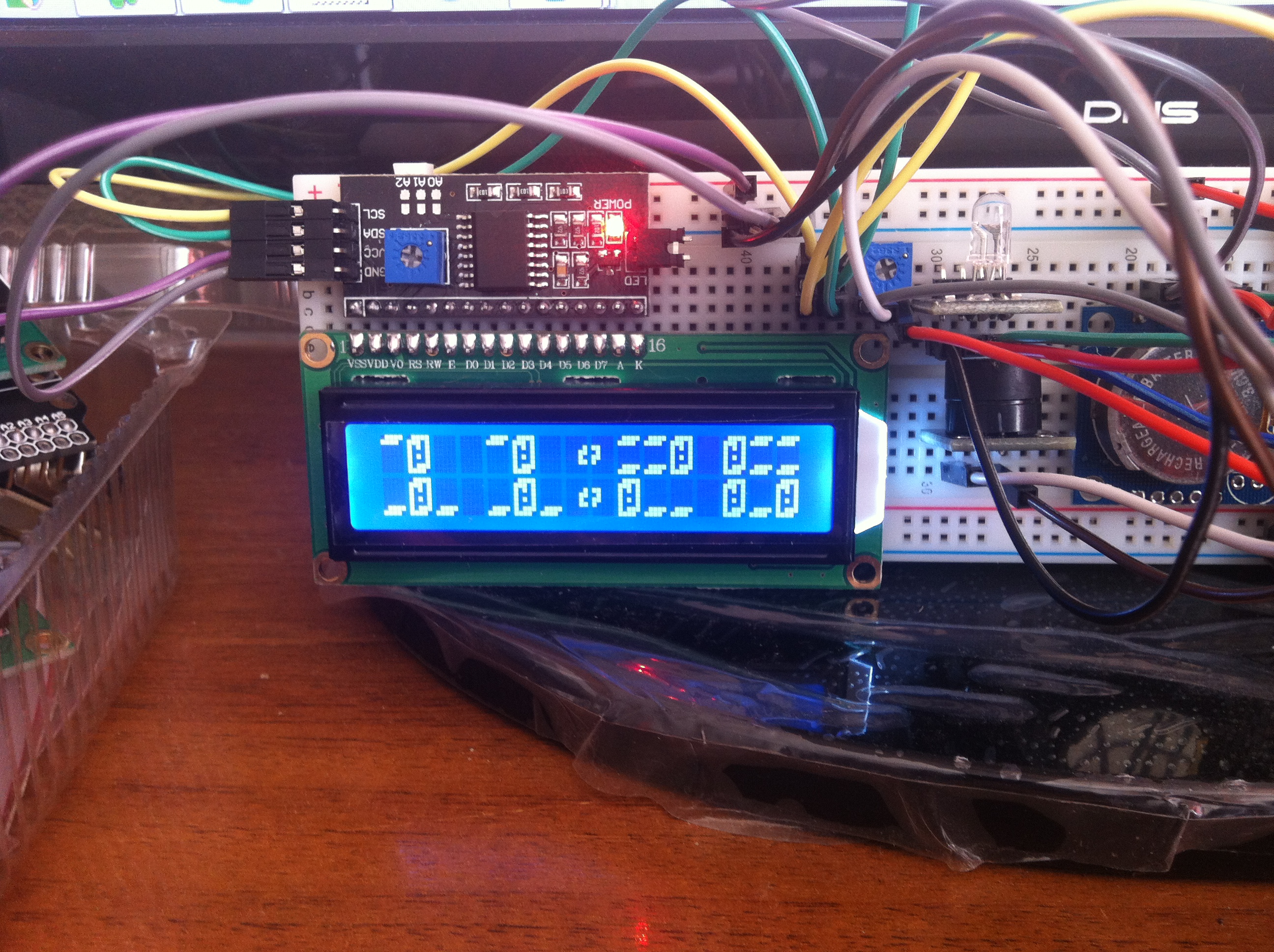
UPD: while the note was in the sandbox, I made several more watch options. Is anyone interested in this? Made a 3x2 pseudo 3d font and added a beeper to tick every second
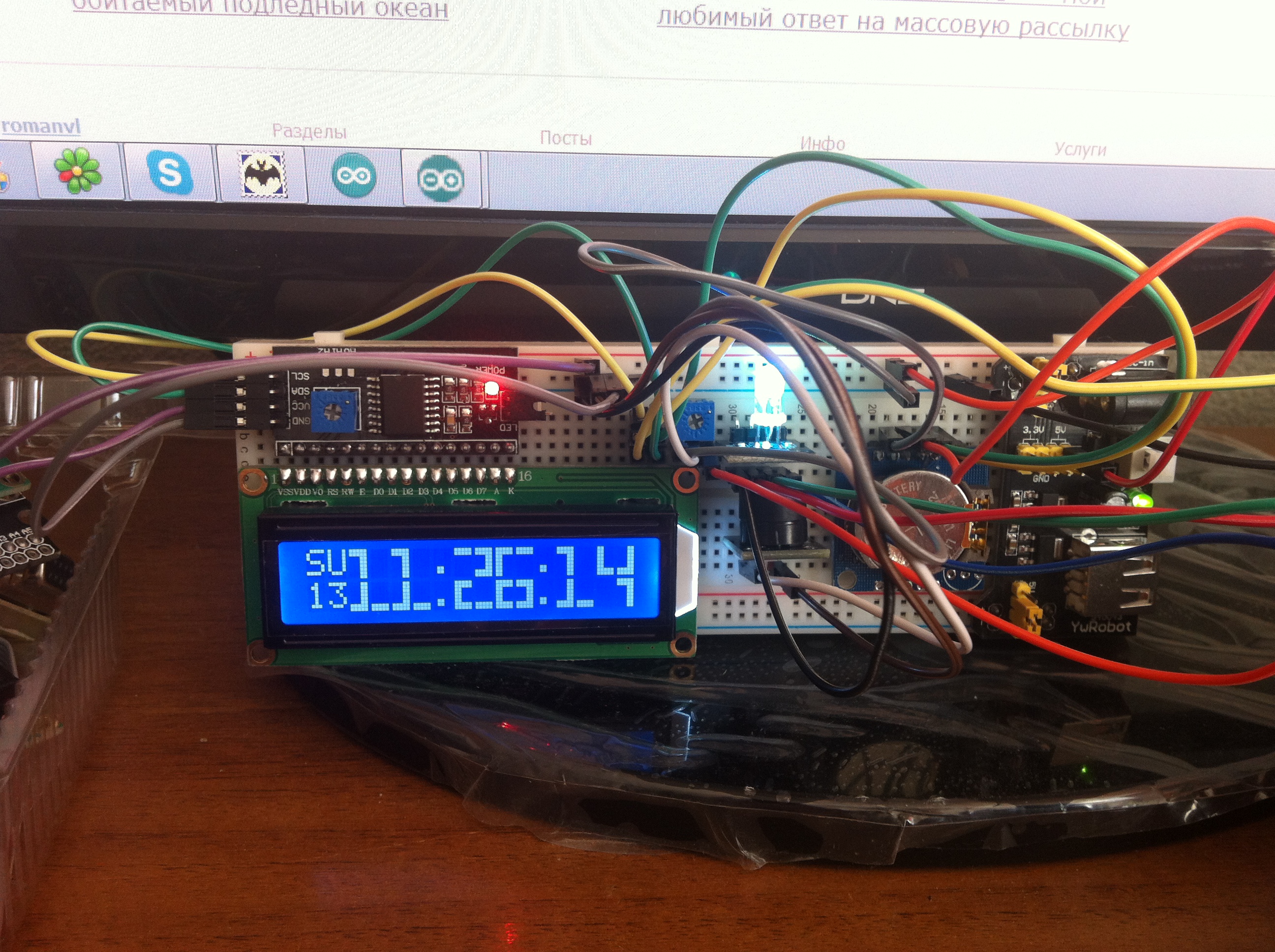
I made a thin font of 2x2 characters for displaying hours, minutes, seconds on one 1602 screen + displaying the day of the week and date. I didn’t find a thin font — I drew it myself by some random picture — in the form of a code. I also added a beeper + RGB LED, which changes color every second. In general, all that was - I screwed everything))
However, for newcomers like me, this information will be useful and save a lot of time.
I2C is the standard for communicating devices on 2 wires, while the number of devices that hangs in parallel on these wires can be very large. Each device has its own address at which the device is accessed. Addressing can be changed if the device has jumpers with which you can set an additional offset relative to the base address that is hard-coded in the device.
It is in a nutshell.
I started with the fact that I bought a 16x2 character LCD display in Ibei. By connecting as standard - I realized that this is not what is needed. A lot of wires - takes a bunch of legs, chaos and disorder.
Googled, I realized that there are displays with interfaces that simplify the connection. googled yet, found an adapter on I2C for my LCD. A month of waiting, hooray, hooked up.
It looks much more interesting!
The problem arose during the search for working libraries and examples. As it turned out later - in the main most famous library bitbucket.org/fmalpartida/new-liquidcrystal/downloads - examples are not working! It took some time and effort =)
Specifically, here are working examples and a link to the library. arduino-info.wikispaces.com/LCD-Blue-I2C
There you can also find descriptions of the various versions of LCD-I2C adapters that you can buy.
I bought this one www.ebay.com/itm/310565362720 it is assembled on a PCF8574 chip
This version of the library requires setting display parameters as follows
LiquidCrystal_I2C lcd(0x27, 2, 1, 0, 4, 5, 6, 7, 3, POSITIVE); // Set the LCD I2C address
where the first number is the address of the device, the rest are assigned control pins of the adapter for a specific display. here the problem was hidden - many examples initialize the screen with incorrect data - while the screen blinks, twitches and does not work.
The correct line, with the address and the necessary pins, depends on the particular display. It’s difficult for a beginner to understand the essence and score the necessary data!
All of the above is a working option. It is probably even better than the library that I am currently using. But it seemed to me too redundant and bulky.
The second library started working immediately. arduino-info.wikispaces.com/file/detail/LiquidCrystal_I2C1602V1.zip/341635514
Unfortunately, I don’t remember where I got the demo for this library, but it uses a simplified LCD setup, which I needed and needed.
LiquidCrystal_I2C lcd(0x27,16,2); // set the LCD address to 0x27 for a 16 chars and 2 line display
In this line, the device address is assigned and the type of display is determined, 16 characters in 2 lines.
The first and second libraries are not compatible with each other! . Examples for one library do not work with another. The following code will refer to the last specified library for working with I2C LCD.
After connecting the screen, I wanted to display something on it. Just the numbers are not interesting. Let there be hours =)) Probably, everyone goes this way, including me. The Arduino software clock allows itself to show the time, but the problem is data reset during shutdown. And since I don’t have any buttons, I have to set the clock through the cable via the COM port through the console. In general, it bothered me very quickly.
Real-time clock RTC1307 is probably the most common watch chip. There are many pluses - a separate microcircuit, independent of the main Arduino power supply with a battery, independent of the main program - time counts for sure! The advantage of watches based on 1307 - I2C. At the same time, you do not need to use any additional outputs - everything is controlled via the same 2 wires as the LCD.
The library for working with I2c watches worked right away, examples are working. github.com/adafruit/RTClib
The program is simple, everything is transparent. Numbers are created by functions in which a number is displayed in separate blocks. Blocks of 5x8 points are set in user characters, there can be a maximum of 8. Examples are taken from the arduino.cc forum.
Drawing takes place in a separate function, the numbers are displayed one at a time. Running crosses - a whim of the author, i.e. mine)) The offset of the numbers is controlled when the draw function is called.
Code for Arduins
// Date and time functions using a DS1307 RTC connected via I2C and Wire lib
#include
#include "RTClib.h"
#include
RTC_DS1307 rtc;
LiquidCrystal_I2C lcd(0x27,16,2);  // set the LCD address to 0x27 for a 16 chars and 2 line display
byte LT[8] =
{
  B00111,
  B01111,
  B11111,
  B11111,
  B11111,
  B11111,
  B11111,
  B11111
};
byte UB[8] =
{
  B11111,
  B11111,
  B11111,
  B00000,
  B00000,
  B00000,
  B00000,
  B00000
};
byte RT[8] =
{
  B11100,
  B11110,
  B11111,
  B11111,
  B11111,
  B11111,
  B11111,
  B11111
};
byte LL[8] =
{
  B11111,
  B11111,
  B11111,
  B11111,
  B11111,
  B11111,
  B01111,
  B00111
};
byte LB[8] =
{
  B00000,
  B00000,
  B00000,
  B00000,
  B00000,
  B11111,
  B11111,
  B11111
};
byte LR[8] =
{
  B11111,
  B11111,
  B11111,
  B11111,
  B11111,
  B11111,
  B11110,
  B11100
};
byte MB[8] =
{
  B11111,
  B11111,
  B11111,
  B00000,
  B00000,
  B00000,
  B11111,
  B11111
};
byte block[8] =
{
  B11111,
  B11111,
  B11111,
  B11111,
  B11111,
  B11111,
  B11111,
  B11111
};
// loop counter
int count = 0;
void setup () {
  Serial.begin(57600);
  Wire.begin();
  rtc.begin();
  lcd.init();                      // initialize the lcd
  lcd.backlight();
  lcd.home();
  lcd.createChar(0,LT);
  lcd.createChar(1,UB);
  lcd.createChar(2,RT);
  lcd.createChar(3,LL);
  lcd.createChar(4,LB);
  lcd.createChar(5,LR);
  lcd.createChar(6,MB);
  lcd.createChar(7,block);
  // sets the LCD's rows and colums:
  lcd.clear();
  if (! rtc.isrunning()) {
    Serial.println("RTC is NOT running!");
    // following line sets the RTC to the date & time this sketch was compiled
    // rtc.adjust(DateTime(__DATE__, __TIME__));
  }
}
void custom0(int x)
{ // uses segments to build the number 0
  lcd.setCursor(x,0); // set cursor to column 0, line 0 (first row)
  lcd.write(0);  // call each segment to create
  lcd.write(1);  // top half of the number
  lcd.write(2);
  lcd.setCursor(x, 1); // set cursor to colum 0, line 1 (second row)
  lcd.write(3);  // call each segment to create
  lcd.write(4);  // bottom half of the number
  lcd.write(5);
}
void custom1(int x)
{
  lcd.setCursor(x,0);
  lcd.write(1);
  lcd.write(2);
  lcd.print(" ");
  lcd.setCursor(x,1);
  lcd.write(4);
  lcd.write(7);
  lcd.write(4);
}
void custom2(int x)
{
  lcd.setCursor(x,0);
  lcd.write(6);
  lcd.write(6);
  lcd.write(2);
  lcd.setCursor(x, 1);
  lcd.write(3);
  lcd.write(4);
  lcd.write(4);
}
void custom3(int x)
{
  lcd.setCursor(x,0);
  lcd.write(6);
  lcd.write(6);
  lcd.write(2);
  lcd.setCursor(x, 1);
  lcd.write(4);
  lcd.write(4);
  lcd.write(5);
}
void custom4(int x)
{
  lcd.setCursor(x,0);
  lcd.write(3);
  lcd.write(4);
  lcd.write(7);
  lcd.setCursor(x, 1);
  lcd.print(" ");
  lcd.print(" ");
  lcd.write(7);
}
void custom5(int x)
{
  lcd.setCursor(x,0);
  lcd.write(3);
  lcd.write(6);
  lcd.write(6);
  lcd.setCursor(x, 1);
  lcd.write(4);
  lcd.write(4);
  lcd.write(5);
}
void custom6(int x)
{
  lcd.setCursor(x,0);
  lcd.write(0);
  lcd.write(6);
  lcd.write(6);
  lcd.setCursor(x, 1);
  lcd.write(3);
  lcd.write(4);
  lcd.write(5);
}
void custom7(int x)
{
  lcd.setCursor(x,0);
  lcd.write(1);
  lcd.write(1);
  lcd.write(2);
  lcd.setCursor(x, 1);
  lcd.print(" ");
  lcd.print(" ");
  lcd.write(7);
}
void custom8(int x)
{
  lcd.setCursor(x,0);
  lcd.write(0);
  lcd.write(6);
  lcd.write(2);
  lcd.setCursor(x, 1);
  lcd.write(3);
  lcd.write(4);
  lcd.write(5);
}
void custom9(int x)
{
  lcd.setCursor(x,0);
  lcd.write(0);
  lcd.write(6);
  lcd.write(2);
  lcd.setCursor(x, 1);
  lcd.print(" ");
  lcd.print(" ");
  lcd.write(7);
}
//void clearnumber(int x)
//{ // clears the area the custom number is displayed in
// lcd.setCursor(x,0);
// lcd.print("   ");
// lcd.setCursor(x,1);
// lcd.print("   ");
//}
void loop () {
  digitalClockDisplay();
  delay(1000);
}
void digitalClockDisplay(){
  // digital clock display of the time
  DateTime now = rtc.now();
  printDigits(now.hour()/10,0);
  printDigits(now.hour()%10,4);
  printDigits(now.minute()/10,9);
  printDigits(now.minute()%10,13);
  // lcd.setCursor(7, 1);
  //  lcd.print(now.second()/10);
  //   lcd.print(now.second()%10);
  if (now.second()%10%2==0){
    lcd.setCursor(7, 0);
    lcd.print("+ ");
    lcd.setCursor(7, 1);
    lcd.print(" +");
    lcd.setCursor(3, 1);
    lcd.print("+");
    lcd.setCursor(12, 0);
    lcd.print("+");
    lcd.setCursor(3, 0);
    lcd.print(" ");
    lcd.setCursor(12, 1);
    lcd.print(" ");
  }
  else
  {
    lcd.setCursor(7, 0);
    lcd.print(" +");
    lcd.setCursor(7, 1);
    lcd.print("+ ");
    lcd.setCursor(3, 0);
    lcd.print("+");
    lcd.setCursor(12, 1);
    lcd.print("+");
    lcd.setCursor(3, 1);
    lcd.print(" ");
    lcd.setCursor(12, 0);
    lcd.print(" ");
  }
  //нарисовали двоеточие
}
void printDigits(int digits, int x){
  // utility function for digital clock display: prints preceding colon and leading 0
  switch (digits) {
  case 0:
    custom0(x);
    break;
  case 1:
    custom1(x);
    break;
  case 2:
    custom2(x);
    break;
  case 3:
    custom3(x);
    break;
  case 4:
    custom4(x);
    break;
  case 5:
    custom5(x);
    break;
  case 6:
    custom6(x);
    break;
  case 7:
    custom7(x);
    break;
  case 8:
    custom8(x);
    break;
  case 9:
    custom9(x);
    break;
  }
}
I would be grateful to experienced programmers if they tell me how to make the code more compact. It seems that there are many opportunities for optimizing the same type of data, but I don’t know how to implement it. I saw examples on the same forum arduino.cc - but did not understand the essence of what was happening - the code is poorly commented out and I do not understand where the legs grow from. Something there was connected with the memory of the LCD controller / I would be grateful for commenting on the code.
UPD: while the note was in the sandbox, I made several more watch options. Is anyone interested in this? Made a 3x2 pseudo 3d font and added a beeper to tick every second
I made a thin font of 2x2 characters for displaying hours, minutes, seconds on one 1602 screen + displaying the day of the week and date. I didn’t find a thin font — I drew it myself by some random picture — in the form of a code. I also added a beeper + RGB LED, which changes color every second. In general, all that was - I screwed everything))