Load Balancers in Microsoft Azure
- Transfer
Microsoft Azure offers load balancing services for virtual machines (IaaS) and cloud services (PaaS) running in the Microsoft Azure cloud. Among other advantages, load balancing allows you to scale your applications and makes it possible to respond more softly when an error or failure occurs.
Load balancing services can be activated both using the settings on the Microsoft Azure management portal and using the service modelyour application. As soon as a hosted service with one or more endpoints is published to the cloud, it is automatically configured to use the load balancer provided by the Microsoft Azure platform. To get all the benefits of elasticity and scalability, you need to have at least two virtual machines configured on the same endpoint.
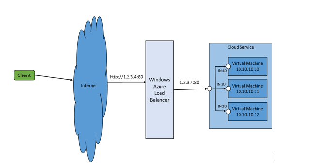
The diagram below shows an example of an application located in Microsoft Azure that uses a load balancer to address incoming traffic (at address / port 1.2.3.4:80) to three virtual machines listening on port 80 (clickable). The following are the key features of load balancer in Microsoft Azure

Load balancing works with all types of services (IaaS and PaaS) and with all operating systems (Windows or any Linux distribution).
Applications in PaaS are configured using the service model . IaaS virtual machines are configured either through the management portal or using PowerShell.
The load balancer in Microsoft Azure is of type Layer-4. This means that it distributes the load between all available virtual machines by calculating the hash function of the traffic arriving at a given endpoint. This hash function is calculated in such a way that all packets arriving within the same connection (TCP or UDP) are sent to the same server. Microsoft Azure Balancer uses a set of 5 fields (source IP address, source port, destination IP address, destination port, protocol type) to calculate the hash used when comparing traffic and an available server. In addition, the hash function was selected so that the distribution of connections to the servers was random enough. However, depending on the type of traffic, it is permissible that different connections will be bound to the same server.They are NOT round-robin, and there is NO request queue, as was sometimes written earlier in some articles and blogs). The basic hash function allows you to get a good distribution of requests with a sufficiently large number of them from different sources.
Microsoft Azure Load Balancing supports TCP and UDP. Clients can specify the protocol type when configuring incoming endpoints in the service model, using PowerShell or the management portal.
A service hosted in the cloud can specify several inbound endpoints and they will automatically be configured in the load balancer service.
Currently, several endpoints with the same port and protocol are not supported. There is also a limit on the maximum available number of endpoints, which now can be up to 150 pieces.
Each service can specify up to 25 endpoints that will not participate in the balancing. These points can be used for internal communication between services.
The hosted service may indicate that this endpoint should have direct access to the virtual machine from outside, bypassing the balancer. This will allow the application to control the possible redirection of the user directly to the virtual machine, without using the services of balancing (and as a result, the probability of requests getting to different nodes).
The load balancer works in conjunction with the Microsoft Azure Compute Service to ensure that if the number of servers for the endpoints is scaled up / down (either when increasing the number of instances for the web or work role or when adding new virtual machines to one balancing group) , the balancer automatically reconfigures itself to these changes.
The load balancer also quietly changes its settings in response to preventive actions of the fabric controller or service updates of the client.
Microsoft Azure Load Balancer provides the ability to monitor the health of various service instances and remove unhealthy instances from the balancing rotation. There are three types of checks: Guest Agent checks (for PaaS), HTTP checks, and TCP checks. In the case of the Guest Agent , the balancer service runs a special agent on the corresponding virtual machine to obtain the status of the service. In the case of the HTTP test, the load balancer relies on polling the specified URL to determine the viability of the application. If the TCP test is selected, the balancer relies on the result of establishing a TCP connection on a specific port.
All return traffic originating from the service is Source NAT (SNAT), using the same virtual IP address as for incoming traffic. We will talk more about SNAT in the following entries.
Microsoft Azure load balancer optimizes traffic between data centers in one region so that placements that communicate with each other through a virtual IP address (VIP) and are in the same region, after establishing a TCP / IP connection, pass through the load balancer together.
Microsoft Azure load balancer allows you to change the VIP of two nodes, moving one node from the test state to the productive and vice versa. The VIP change operation allows customers to use one VIP to communicate with the service, while the new version of the service is in the process of deployment (deploy). The new version can be posted and tested without affecting the main application, in a test environment. As soon as the new version passes all the checks, it can be put into commercial operation by “selecting” the VIP from the current virtual machine and assigning it to a new one. In this case, all current connections to the old machine remain untouched, and new connections are sent to the "new" server.
Next, we will see how most of the above can be used in the cloud service. The PaaS model of the environment we want to receive is shown below: This solution has two Frontend (FE) roles and one Backend (BE) role. The FE role opens up four balanced endpoints using the http, tcp, and udp protocols. One of the points is also used to monitor performance. The BE role opens up three endpoints with the http, tcp, and udp protocols. Both roles (FE and BE) have one direct endpoint per service instance. The service described below is configured using the service model (some features of the scheme have been removed for readability)

Consider this model. We start by defining the type of performance testing that the balancer should use to verify the health of the service:
It says here that we want to use testing via HTTP using the relative path “Probe.aspx”. This test will later be connected to the endpoint.
Then we define the role of EF as WorkerRole. It has several endpoints (http, tcp, udp)
Until we set up our own performance monitoring, performance testing is performed using the guest agent and can be changed by the service using the StatusCheck event .
Then we define an additional endpoint for the 80th port, which uses its own test (MyProbe)
The load balancer combines information about the endpoint and testing to obtain a URL of the form http: // {DIP of VM}: 80 / Probe.aspx, which will then be used to test the service’s health. The service will understand (by the logs?) That the same IP address periodically refers to it. These are the status requests coming from the host where the virtual machine is located.
The service must respond with HTTP code 200 so that the balancer considers it operational. Any other status code takes the virtual machine out of rotation.
Test setup also sets the frequency of polls. In our case, the balancer polls the service every 15 seconds. If the answer was not received within 30 seconds (two polling intervals), the test is considered failed and the virtual machine is removed from rotation. Similarly, if the virtual machine is pulled out of rotation, but a positive response begins to come from it, this service immediately returns to rotation. If the service has been in the running / not running mode for a long time, the load balancer can decide on the delay to enter rotation until it responds positively to a sufficient number of tests.
The FE service also provides a set of direct endpoints, one for each instance, which connects to the instance directly on the specified port:
The definition above establishes a connection on ports 10110, 10111, etc. and translates it to port 80 for all virtual machines with FE roles. Such a function can be used in several scenarios:
Finally, the FE role provides an internal endpoint that can be used for interaction between FE and BE:
Each role can access its endpoints, as well as points that provide other roles, using the RoleEnvironment class .
The BE role is also configured as WorkerRole. It does not provide any balanced endpoints, only internal points using http, tcp and udp:
The BE role also provides a direct endpoint that allows you to connect directly to a BE instance:
The definition above establishes a connection on ports 10110, 10111, etc. and translates it to port 80 for all virtual machines with BE roles.
We hope that the example above will show you how to use the various capabilities of the load balancer together in the modeling of services.
In the following entries, we will demonstrate this example in action and show examples of source codes. We will also tell you more about:
Also, please send your inquiries about what you would like to know in more detail.
Marios Zikos for the Microsoft Azure Networking Team.
Load balancing services can be activated both using the settings on the Microsoft Azure management portal and using the service modelyour application. As soon as a hosted service with one or more endpoints is published to the cloud, it is automatically configured to use the load balancer provided by the Microsoft Azure platform. To get all the benefits of elasticity and scalability, you need to have at least two virtual machines configured on the same endpoint.
The diagram below shows an example of an application located in Microsoft Azure that uses a load balancer to address incoming traffic (at address / port 1.2.3.4:80) to three virtual machines listening on port 80 (clickable). The following are the key features of load balancer in Microsoft Azure
IaaS / PaaS Support
Load balancing works with all types of services (IaaS and PaaS) and with all operating systems (Windows or any Linux distribution).
Applications in PaaS are configured using the service model . IaaS virtual machines are configured either through the management portal or using PowerShell.
Layer-4 balancer, hash distribution
The load balancer in Microsoft Azure is of type Layer-4. This means that it distributes the load between all available virtual machines by calculating the hash function of the traffic arriving at a given endpoint. This hash function is calculated in such a way that all packets arriving within the same connection (TCP or UDP) are sent to the same server. Microsoft Azure Balancer uses a set of 5 fields (source IP address, source port, destination IP address, destination port, protocol type) to calculate the hash used when comparing traffic and an available server. In addition, the hash function was selected so that the distribution of connections to the servers was random enough. However, depending on the type of traffic, it is permissible that different connections will be bound to the same server.They are NOT round-robin, and there is NO request queue, as was sometimes written earlier in some articles and blogs). The basic hash function allows you to get a good distribution of requests with a sufficiently large number of them from different sources.
Multiple Protocol Support
Microsoft Azure Load Balancing supports TCP and UDP. Clients can specify the protocol type when configuring incoming endpoints in the service model, using PowerShell or the management portal.
Multiple Endpoint Support
A service hosted in the cloud can specify several inbound endpoints and they will automatically be configured in the load balancer service.
Currently, several endpoints with the same port and protocol are not supported. There is also a limit on the maximum available number of endpoints, which now can be up to 150 pieces.
Internal Endpoint Support
Each service can specify up to 25 endpoints that will not participate in the balancing. These points can be used for internal communication between services.
Direct Endpoint Support
The hosted service may indicate that this endpoint should have direct access to the virtual machine from outside, bypassing the balancer. This will allow the application to control the possible redirection of the user directly to the virtual machine, without using the services of balancing (and as a result, the probability of requests getting to different nodes).
Automatic configuration changes when scaling up / down, updating and maintenance of a service
The load balancer works in conjunction with the Microsoft Azure Compute Service to ensure that if the number of servers for the endpoints is scaled up / down (either when increasing the number of instances for the web or work role or when adding new virtual machines to one balancing group) , the balancer automatically reconfigures itself to these changes.
The load balancer also quietly changes its settings in response to preventive actions of the fabric controller or service updates of the client.
Monitoring
Microsoft Azure Load Balancer provides the ability to monitor the health of various service instances and remove unhealthy instances from the balancing rotation. There are three types of checks: Guest Agent checks (for PaaS), HTTP checks, and TCP checks. In the case of the Guest Agent , the balancer service runs a special agent on the corresponding virtual machine to obtain the status of the service. In the case of the HTTP test, the load balancer relies on polling the specified URL to determine the viability of the application. If the TCP test is selected, the balancer relies on the result of establishing a TCP connection on a specific port.
Source NAT
All return traffic originating from the service is Source NAT (SNAT), using the same virtual IP address as for incoming traffic. We will talk more about SNAT in the following entries.
Optimization of traffic within the data center
Microsoft Azure load balancer optimizes traffic between data centers in one region so that placements that communicate with each other through a virtual IP address (VIP) and are in the same region, after establishing a TCP / IP connection, pass through the load balancer together.
Exchange virtual IP address
Microsoft Azure load balancer allows you to change the VIP of two nodes, moving one node from the test state to the productive and vice versa. The VIP change operation allows customers to use one VIP to communicate with the service, while the new version of the service is in the process of deployment (deploy). The new version can be posted and tested without affecting the main application, in a test environment. As soon as the new version passes all the checks, it can be put into commercial operation by “selecting” the VIP from the current virtual machine and assigning it to a new one. In this case, all current connections to the old machine remain untouched, and new connections are sent to the "new" server.
Example: load balancing service
Next, we will see how most of the above can be used in the cloud service. The PaaS model of the environment we want to receive is shown below: This solution has two Frontend (FE) roles and one Backend (BE) role. The FE role opens up four balanced endpoints using the http, tcp, and udp protocols. One of the points is also used to monitor performance. The BE role opens up three endpoints with the http, tcp, and udp protocols. Both roles (FE and BE) have one direct endpoint per service instance. The service described below is configured using the service model (some features of the scheme have been removed for readability)

<ServiceDefinitionname="ProbeTenant"><LoadBalancerProbes><LoadBalancerProbename="MyProbe"protocol="http"path="Probe.aspx"intervalInSeconds="5"timeoutInSeconds="100" /></LoadBalancerProbes><WorkerRolename="BERole"vmsize="Small"><Endpoints><InternalEndpointname="BE_InternalEP_Tcp"protocol="tcp" /><InternalEndpointname="BE_InternalEP_Udp"protocol="udp" /><InternalEndpointname="BE_InternalEP_Http"protocol="http"port="80" /><InstanceInputEndpointname="InstanceEP_BE"protocol="tcp"localPort="80"><AllocatePublicPortFrom><FixedPortRangemin="10210"max="10220" /></AllocatePublicPortFrom></InstanceInputEndpoint></Endpoints></WorkerRole><WorkerRolename="FERole"vmsize="Small"><Endpoints><InputEndpointname="FE_External_Http"protocol="http"port="10000" /><InputEndpointname="FE_External_Tcp"protocol="tcp"port="10001" /><InputEndpointname="FE_External_Udp"protocol="udp"port="10002" /><InputEndpointname="HTTP_Probe"protocol="http"port="80"loadBalancerProbe="MyProbe" /><InstanceInputEndpointname="InstanceEP"protocol="tcp"localPort="80"><AllocatePublicPortFrom><FixedPortRangemin="10110"max="10120" /></AllocatePublicPortFrom></InstanceInputEndpoint><InternalEndpointname="FE_InternalEP_Tcp"protocol="tcp" /></Endpoints></WorkerRole></ServiceDefinition>Consider this model. We start by defining the type of performance testing that the balancer should use to verify the health of the service:
<LoadBalancerProbes><LoadBalancerProbename="MyProbe"protocol="http"path="Probe.aspx"intervalInSeconds="5"timeoutInSeconds="100" /></LoadBalancerProbes>It says here that we want to use testing via HTTP using the relative path “Probe.aspx”. This test will later be connected to the endpoint.
Then we define the role of EF as WorkerRole. It has several endpoints (http, tcp, udp)
<InputEndpointname="FE_External_Http"protocol="http"port="10000" /><InputEndpointname="FE_External_Tcp"protocol="tcp"port="10001" /><InputEndpointname="FE_External_Udp"protocol="udp"port="10002" />Until we set up our own performance monitoring, performance testing is performed using the guest agent and can be changed by the service using the StatusCheck event .
Then we define an additional endpoint for the 80th port, which uses its own test (MyProbe)
<InputEndpointname="HTTP_Probe"protocol="http"port="80"loadBalancerProbe="MyProbe" />The load balancer combines information about the endpoint and testing to obtain a URL of the form http: // {DIP of VM}: 80 / Probe.aspx, which will then be used to test the service’s health. The service will understand (by the logs?) That the same IP address periodically refers to it. These are the status requests coming from the host where the virtual machine is located.
The service must respond with HTTP code 200 so that the balancer considers it operational. Any other status code takes the virtual machine out of rotation.
Test setup also sets the frequency of polls. In our case, the balancer polls the service every 15 seconds. If the answer was not received within 30 seconds (two polling intervals), the test is considered failed and the virtual machine is removed from rotation. Similarly, if the virtual machine is pulled out of rotation, but a positive response begins to come from it, this service immediately returns to rotation. If the service has been in the running / not running mode for a long time, the load balancer can decide on the delay to enter rotation until it responds positively to a sufficient number of tests.
The FE service also provides a set of direct endpoints, one for each instance, which connects to the instance directly on the specified port:
<InstanceInputEndpointname="InstanceEP"protocol="tcp"localPort="80"><AllocatePublicPortFrom><FixedPortRangemin="10110"max="10120" /></AllocatePublicPortFrom></InstanceInputEndpoint>The definition above establishes a connection on ports 10110, 10111, etc. and translates it to port 80 for all virtual machines with FE roles. Such a function can be used in several scenarios:
- Provide access to the specified instance and perform actions only with it
- Redirect the user application to a specific instance after it has passed through a balanced endpoint. This can be used for sticky sessions. But it should be borne in mind that this can lead to an overload of this instance.
Finally, the FE role provides an internal endpoint that can be used for interaction between FE and BE:
<InternalEndpointname="FE_InternalEP_Tcp"protocol="tcp" />Each role can access its endpoints, as well as points that provide other roles, using the RoleEnvironment class .
The BE role is also configured as WorkerRole. It does not provide any balanced endpoints, only internal points using http, tcp and udp:
<InternalEndpointname="BE_InternalEP_Tcp"protocol="tcp" /><InternalEndpointname="BE_InternalEP_Udp"protocol="udp" /><InternalEndpointname="BE_InternalEP_Http"protocol="http"port="80" />The BE role also provides a direct endpoint that allows you to connect directly to a BE instance:
<InstanceInputEndpointname="InstanceEP_BE"protocol="tcp"localPort="80"><AllocatePublicPortFrom><FixedPortRangemin="10210"max="10220" /></AllocatePublicPortFrom></InstanceInputEndpoint>The definition above establishes a connection on ports 10110, 10111, etc. and translates it to port 80 for all virtual machines with BE roles.
We hope that the example above will show you how to use the various capabilities of the load balancer together in the modeling of services.
In the following entries, we will demonstrate this example in action and show examples of source codes. We will also tell you more about:
- How SNAT Works
- Custom tests
- Virtual networks
Also, please send your inquiries about what you would like to know in more detail.
Marios Zikos for the Microsoft Azure Networking Team.