The invisible difficulties of rocket technology: Part 4. More about engines and tanks
The tribute that has to be paid to the imperfection of our world to the developers of rocketry is varied and unpleasant. Today we’ll talk about what you have to pay for improving the performance of liquid-propellant engines and those inconspicuous problems that await tank designers.
LRE operation schemes
The existence of different schemes allows developers to choose the right one with the desired advantages (ease of use, ease of production, high traction or high specific impulse) and acceptable disadvantages.
Displacement Feed
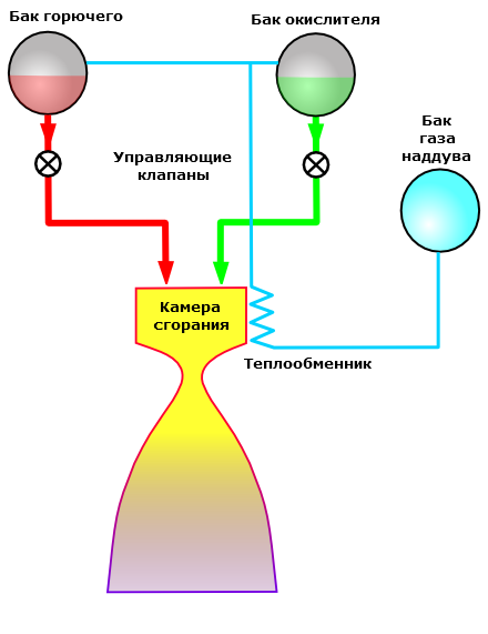
The easiest option. The boost gas pressure (at first there was nitrogen, now massively switched to helium) provides the necessary pressure parameters at the engine inlet. The first rocket experiments of the GIRD and Goddard were carried out on the displacement feed, but it did not leave the scene over time. This scheme is used in propulsion systems of satellites and spacecraft. Unions, Shuttles, Apollo used it. Particularly good displacement flow is combined with the UDMH / AT fuel pair due to its autoignition. It turns out a simple, reliable engine with the possibility of multiple inclusion.
Advantages:
- Simplicity.
- Reliability.
- Cheapness.
- No mass loss on the turbopump.
- High performance for low thrust engines
Disadvantages:
- Low specific impulse.
- Poorly suited for high thrust engines.
Open circuit
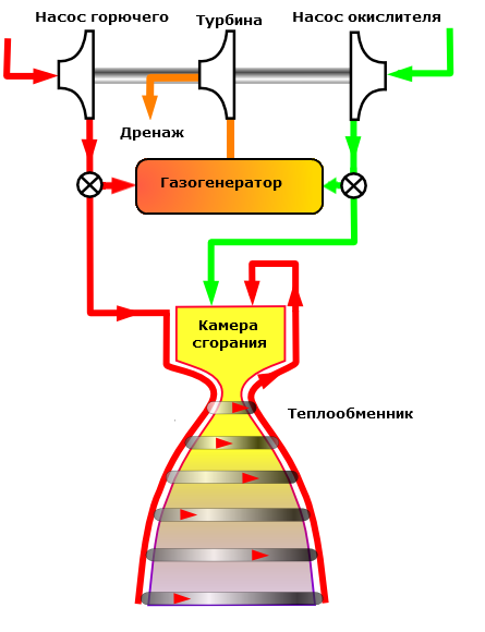
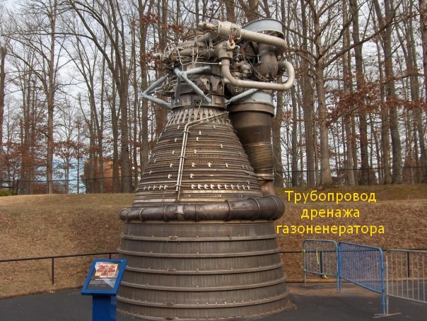
To increase traction, specific impulse and engine power, a pump was already needed. Only the turbine could provide the required parameters. In the first "real" missiles - "V-2", "R-7" a separate working substance was used to drive the turbine - concentrated hydrogen peroxide, but then they switched to burning a small fraction of the fuel components. At first, the gas generator exhaust was simply dumped to the side, a very spectacular torch was obtained: the

Atlas launch vehicle was launched. Pay attention to the size, power and color of the torch. It is clearly seen that TNA works on excess fuel that burns out in the air.
The drainage of the generator gas directly overboard looked wasteful, so it began to be sent to the supercritical part of the nozzle - and a little bit of UI will add, and how the curtain will work:
The classic picture is the F-1 engine.
However, the drainage of an open circuit gas generator has another interesting use case - as a roll control engine:
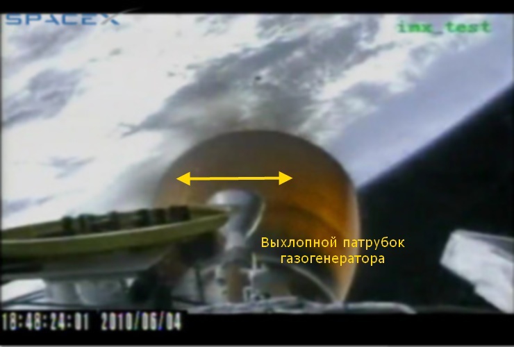
The second stage of the Falcon-9 LV. The rotation of the exhaust pipe leads to a twisting force that controls the roll of the stage.
Watch in dynamics (from the third minute)
An open circuit is being used now, and is unlikely to disappear in the near future. Due to the relatively small loss of MI, it allows you to make a more powerful engine ( F-1 ) or a cheaper engine ( RS-68 ) or make development possible for a team with limited resources ( Merlin ).
Advantages:
- Simpler and cheaper than a closed circuit.
Disadvantages:
- Less specific impulse than a closed circuit.
Closed circuit
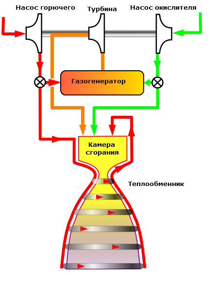
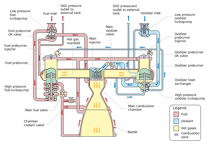
The logical solution to increase the engine’s SI was an attempt to direct the gas generator exhaust into the combustion chamber so that it burns out under the best conditions for creating traction. This task turned out to be quite difficult - there is a lot of pressure in the combustion chamber, additional questions arise about the stability of the engine, because one more feedback “TNA-combustion chamber” is added. Engines of the closed circuit were the first to be made by the USSR - NK-15 and NK-33 were put on the heavy N-1 rocket, RD-253 works on the Proton. The United States took up this circuit quite late - the first rocket engine in the US closed circuit was the SSME marching shuttle engine, which, however, became the first closed-cycle engine on an oxygen / hydrogen pair.
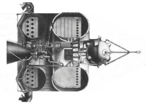
Admire the complexity of the engine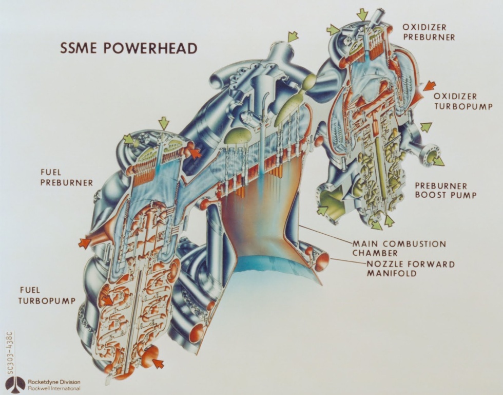
Advantages:
- The largest IA.
Disadvantages:
- The most complicated and expensive scheme.
Phase transition circuit

An elegant “hack” of rocket engine physics - the need to cool the engine nozzle is used as an energy source for the operation of a turbopump. The circuit was invented for the RL-10 engine , which has been used in the Centaur acceleration unit for fifty years.
Advantages:
- No mass loss on TNA.
- Simplicity of design.
- Reliability.
Disadvantages:
- Only suitable for oxygen-hydrogen pairs.
- The pressure is lower than in the circuit with TNA, therefore, the UI is lower.
Tank insides
Inside the tanks of the launch vehicle is also a lot of interesting things. The tanks are one above the other, therefore, pipelines for supplying the “upper” component, boost pipelines are needed, and also, perhaps, it is necessary to solve the problem of finding nearby fuel components with different temperatures. And there is also the problem of fuel fluctuation, which also needs to be addressed.
Piping components

This is the fuel tank (lower) of the first stage of the Soyuz-2.1v launch vehicle. Pay attention to the large corrugated pipe. This is an oxidizer conduit. Since the oxidizing agent is liquid oxygen, it is necessary to put thermal insulation so that kerosene does not freeze on the pipe. Alas, all this requires additional mass.

And this is the Angara launch vehicle. Highlighted in yellow - a pipeline that performs the same function. Judging by the proportions, this is also an oxidizer pipeline (oxygen tanks are larger than kerosene for an oxygen-kerosene pair), but taken out from the side to simplify and reduce the cost of production. On the one hand, this is unaesthetic, but the digital control system will cope with missile asymmetry.
Inter-tank compartment
At the second and third stages of the Saturn-V rocket, a very beautiful solution was used - the oxygen and hydrogen tanks had a common wall: on the
left - the first stage with an inter-tank compartment, on the right - the second stage with a common wall. Red is fuel, blue is an oxidizing agent.
The difficulty was that liquid hydrogen and oxygen had a temperature difference of 70 degrees Celsius. Therefore, the wall consisted of two layers of aluminum with thermal insulation between them. This design saved as much as 3.6 tons in the second stage. Curiously, the Space Shuttle’s fuel tank was, in a sense, a step back; it had a classic inter-tank compartment.
Boost pipes
If you deployed the SSME scheme above, you saw gasified hydrogen and oxygen exits there. They were used to boost the corresponding tanks. On the one hand, they saved weight on individual pressurized gas tanks, on the other hand, they received an additional pipeline:

This picture is large.
Damping partitions
If you carefully examined the pictures of tank sections, you saw rings of different widths and crosses at the bottom of the shuttle tanks. These are special elements for damping fuel vibrations.
The crosses at the bottom of the shuttle's fuel tank are used to prevent the formation of a funnel when the tank is empty. The fact is that the funnel can lead to the suction of the gaseous component of the fuel, which can cause problems in pipelines and engines.
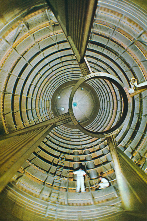
Ring-shaped elements are used to damp fuel vibrations. Since it is liquid, overflowing fuel to one wall during a maneuver can cause problems for the stabilization system. The partitions can be very large, as in the first stage of Saturn I:
Or practically be absent, as in the third stage of Saturn V:
The video is long, but I recommend watching it - the behavior of liquid hydrogen during acceleration of a rocket and in zero gravity is very interesting.
The general rule is that the more maneuvers expected from a step, the larger the size of the partitions is placed. For example, the Soviet block “E” is the third stage of the Vostok launch vehicle. Here the partitions are the size of almost the entire height of the tank, because the unit can very actively maneuver, and you can’t let the fuel splash around:
And all this, alas, is an additional mass cost.
Tank emptying and synchronization system
Another problem that has to be addressed. Firstly, the combustion of each engine is somewhat unique. There will certainly be small variations in traction and fuel component consumption. Even for one engine, it is necessary to install a special system so that the fuel and oxidizer end simultaneously. And if we have several tanks or side steps, then we have to install a special system that will ensure the simultaneous completion of components in several steps. Now this system is also called the fuel consumption control system and consists of a set of level sensors and a digital computer, which, in addition to rocket control, also solves this problem: the
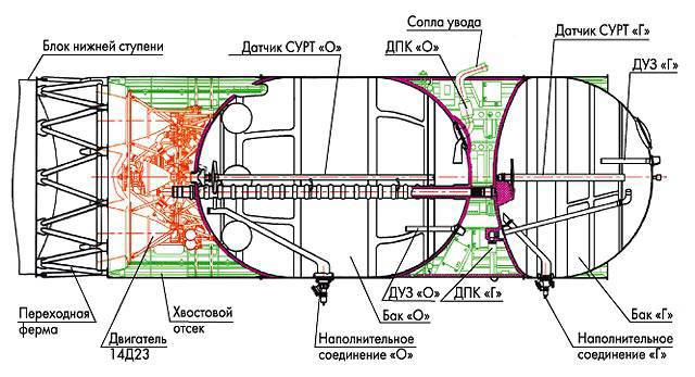
third stage of the Soyuz launch vehicle. Along the axis of the tanks are level sensors for SURT.
However, even despite the efforts of SURT, she herself has a limitation of accuracy, so some small fraction of the fuel is still lost. It is taken into account when refueling, adding to the so-called. "Guaranteed fuel supply."
Epilogue
I recommend watching the series “Moon Machines” ( Russian version , English version ). Very well and clearly shown the difficulties that have to be solved in the design of space technology.
For navigation: