How to deal with IA-32 code or features of the Simics decoder
Hi% username%!
Decoding IA-32 code is a daunting task. To make sure of this, you can refer to the Intel Software Development Manual or to articles previously written on the hub: Prefixes in the IA-32 command system , Does your disassembler work correctly? . Let's see how the functionally accurate full-platform simulator Wind River Simics is struggling with this task , allowing you to create a high-performance virtual environment in which any electronic system, starting from one board and ending with entire multiprocessor, multi-core and even multi-machine systems, can be defined, developed and launched .
 Most libraries for decoding IA-32 instructions generate or use correspondence tables between operation codes and instructions. An example of using this approach is described in the DIY Disassembler article . However, decoding of prefixes and arguments is usually hand-written: libopcodes , metasm , beaengine , distorm . This approach has a significant drawback - adding support for new instruction sets will require a lot of manual work.
There are other ways to create decoders, for example using the GDSL language . This approach is universal and allows you to create decoders for any architecture.
Simics uses a completely different,no less universal approach for working with IA-32 instructions, called separate decoding. Simics also has the ability to use external decoders, but more on that later.
In a real processor, a separate block of logic chips is responsible for the decoding task. In the simulator, it corresponds to some procedure written in a programming language. Consider what comes to her input and what results should be expected from her.
Obviously, an array of bytes of a known length obtained at the phase of fetching commands ( eng. Fetch) is supplied to the decoder input . In addition, he should be aware of the current processor mode (see Prefixes in the IA-32 Command System ).
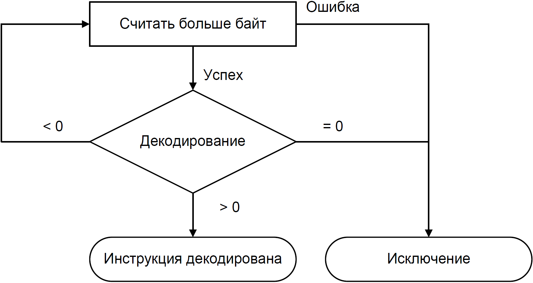
As a result of the work, the decoder should return an error code and sequence analysis results in the form of a list of result fields. The following values are possible for the error code:
The figure below shows an example of an algorithm that combines iteration of the Fetch and Decode phases and allows decoding for variable-length instructions.
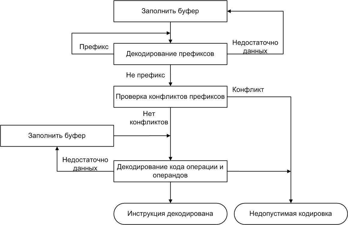
The main idea of this approach is to separate the decoding phase into two stages:
It goes without saying that the second phase depends on the result, since in the IA-32 command system there is such a thing as mandatory prefixes, which are actually part of the operation code (see Prefixes in the IA-32 command system ).
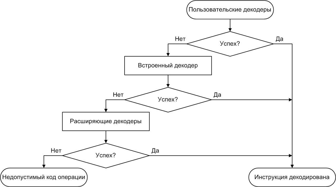
Simics allows you to connect additional decoders using the external interfaces described in the Model Builder User's Guide, which comes with the simulator. Thus, you can connect many external decoders and call them in turn until some decoder gives a positive result or the list of decoders does not end. In this case, it will be possible to conclude that in this model this operation code is considered invalid.

To provide flexibility, external decoders in Simics are divided into two types:
The difference between the proposed types of decoders is that the custom decoders are launched first - even before the built-in call, which allows you to redefine the decoding results that are wired into the original model. Expanding ones are launched only when neither the user nor the built-in decoders could recognize the instruction.
That is, the user, while developing any ISA, can simply slip his decoder and see what changes, without changing the original processor model.
In addition, this approach allows you to reuse existing decoders instead of writing them from scratch, which significantly reduces the model development time.
Decoding IA-32 code is a daunting task. To make sure of this, you can refer to the Intel Software Development Manual or to articles previously written on the hub: Prefixes in the IA-32 command system , Does your disassembler work correctly? . Let's see how the functionally accurate full-platform simulator Wind River Simics is struggling with this task , allowing you to create a high-performance virtual environment in which any electronic system, starting from one board and ending with entire multiprocessor, multi-core and even multi-machine systems, can be defined, developed and launched .
Most libraries for decoding IA-32 instructions generate or use correspondence tables between operation codes and instructions. An example of using this approach is described in the DIY Disassembler article . However, decoding of prefixes and arguments is usually hand-written: libopcodes , metasm , beaengine , distorm . This approach has a significant drawback - adding support for new instruction sets will require a lot of manual work. There are other ways to create decoders, for example using the GDSL language . This approach is universal and allows you to create decoders for any architecture.
Simics uses a completely different,
Decoder procedure input and output
In a real processor, a separate block of logic chips is responsible for the decoding task. In the simulator, it corresponds to some procedure written in a programming language. Consider what comes to her input and what results should be expected from her.
Obviously, an array of bytes of a known length obtained at the phase of fetching commands ( eng. Fetch) is supplied to the decoder input . In addition, he should be aware of the current processor mode (see Prefixes in the IA-32 Command System ).
As a result of the work, the decoder should return an error code and sequence analysis results in the form of a list of result fields. The following values are possible for the error code:
- Decoding is successful (return code is equal to instruction length> 0). The byte array was recognized as a valid instruction, and the list of fields contains information about the operation code and its arguments.
- Decoding is not successful (code 0). Not a single instruction defined in the architecture matches an input byte array. At the same time, the content of the result fields does not make sense. What happens in this situation next at the execution stage? It depends on the architecture. Most often, the inability to decode leads to the generation of an exception, and in some cases an incorrect instruction can be interpreted as NOP - the absence of an operation.
- For ISA with variable instruction length, the third situation is possible - the input data is not enough to make an unambiguous decision (code <0). In other words, only a part of the instruction was transmitted to the decoder input, and it, having no information about which bytes go further in the memory, reports this.
The figure below shows an example of an algorithm that combines iteration of the Fetch and Decode phases and allows decoding for variable-length instructions.
Separate Decoding
The main idea of this approach is to separate the decoding phase into two stages:
- Decoding of prefixes. This stage includes both decoding all the prefixes and checking for conflicts between them.
- Decoding of operation codes and operands. This stage involves calling the decoder generated using SimGen .
It goes without saying that the second phase depends on the result, since in the IA-32 command system there is such a thing as mandatory prefixes, which are actually part of the operation code (see Prefixes in the IA-32 command system ).
Using external decoders
Simics allows you to connect additional decoders using the external interfaces described in the Model Builder User's Guide, which comes with the simulator. Thus, you can connect many external decoders and call them in turn until some decoder gives a positive result or the list of decoders does not end. In this case, it will be possible to conclude that in this model this operation code is considered invalid.
To provide flexibility, external decoders in Simics are divided into two types:
- Custom decoders ( Eng. User decoders) - decoders, which can override any existing code operation, as well as, of course, can add the ability to decode new instructions.
- Widening decoders ( Engl. Extension decoders) - decoders intended for expansion capabilities built-in decoder, i.e. to decode the instructions not supported by them.
The difference between the proposed types of decoders is that the custom decoders are launched first - even before the built-in call, which allows you to redefine the decoding results that are wired into the original model. Expanding ones are launched only when neither the user nor the built-in decoders could recognize the instruction.
And one more obvious point
User decoders are defined by the user, while the expanding decoders are “wired” into the model; they cannot be changed.
That is, the user, while developing any ISA, can simply slip his decoder and see what changes, without changing the original processor model.
Example
You suddenly wanted to swap the NOP and HLT instructions and see if your system worked. To do this, you simply write a small decoder that decodes 0x90 as HLT, and 0xF4 as NOP, attach it to Simics and try to start the system.
In addition, this approach allows you to reuse existing decoders instead of writing them from scratch, which significantly reduces the model development time.