February 28, 2014 at 20:19
Thermostating in the house
In the previous article, “Weather Station with Ethernet and a Tablet as a Display Device,” I talked about how I organized the collection, storage, processing, and output of weather data in my home and beyond. It was also mentioned there that the principles underlying the system make it possible to build something broader than simply collecting weather data, and an article about thermostating was announced. It's time to keep the promise and talk about this very thermostating.
A modern country house with autonomous heating usually involves a gas boiler. In the most primitive version, heating is controlled in two ways:
At the same time, modern boilers, as a rule, support external control. The main purpose of this feature is to connect various kinds of temperature controllers that allow you to set the boiler power not in abstract degrees of water in the batteries (the same water temperature figures can lead to completely different results depending on external conditions), but in terms of a much more understandable target temperature of the place where the regulator is installed. “Out of band management” can mean anything, but usually it’s either some proprietary protocol of a particular manufacturer of equipment (as, for example, Bosch does), or one of the implementations of the OpenTherm protocol.
The main problem of the mentioned temperature regulators for me is the price. With a boiler cost of about 25,000 rubles, the price of a regulator of 9,000 rubles seems somewhat overpriced.
As a result of bilateral consultations with the toad, an estimate was agreed, one and a half orders of magnitude lower than the cost of a typical commercial regulator, after which the development of options for the implementation of a home-grown regulator began.
The regulator set the following goals:
The study of the possibilities of construction began with the study of the boiler's capabilities for external control. After removing the casing, a connector was found on which a jumper hung. Studying the documentation for the boiler gave us hope that it is the same connector for external control. Here it is necessary to mention the special zeal with which the Russian-language documentation was prepared for my Italian boiler Ferroli. The documentation has a description of the connectors. On the contrary, I was interested in the sacred inscription "Unit of environment." Intuition persistently hinted that this is the work of translators unfamiliar with the subject area, it would be necessary to look for English-language documentation (since they should have been more literally translated into English). After digging out from the Internet PDFs with the English version of the boiler manual, everything became clear, opposite the same connector the text “Room unit” flaunted. There was a little icon, which, with a certain amount of imagination, could be mistaken for the OpenTherm logo. “This is what you need,” I thought, and began to plan brutal experiments on the boiler (it was -25 outside the window, so it was time to burn the heater electronics).
Here you need to make the necessary excursion to OpenTherm. The protocol is neither closed nor open. Not closed because if you have a specification, then no one will chase you. Not open because no one will just give you the protocol specification. Join the OpenTherm Alliance for $$$$$$$, then get access to the body of the protocol. Rummaging in the depths of the Internet, I caught the OT2.2 specification.
At the physical level, OpenTherm are two low-current lines with an open voltage of the order of 42V. The control device, when connected to them, can simultaneously power and control the slave.
The specification defines two protocol levels: OT / + and OT / Lite.
The first is a protocol in the sense in which the majority of people in IT understand this word. Those. this is a certain set of requests and responses that go between the control device (it’s also the master unit, it’s also the room unit, in our case it is the regulator) and the slave (it’s the slave unit, this is the boiler). The protocol is divided into the mandatory part, which includes the commands “turn on / off the burner”, “report the status” and “set the very water temperature after the heating circuit (the parameter is called setpoint)”. Optional - a bunch of others, ranging from the control of the modulation of the flame to the removal of gas flow, pressure and water velocity in the circuit. In this case, the control device controls the change in voltage in these lines, and the slave responds with a change in current.
OT / Lite is a simpler thing. If you are not smart enough to implement OT / +, you can simply generate a PWM signal, according to the duty cycle of which the boiler will control the setpoint installation.
In addition, the specification also defines a test mode in which the lines are short-circuited. In this mode, the boiler heats up until it gets bored (read until the upper bar of the water temperature installed on the boiler itself is reached). So the boiler works without an external regulator (therefore, there was a jumper at the opening).
I’ll immediately dispel the intrigue and say that it did not work to steer the boiler over OpenTherm. The interface circuit was assembled and even a library was written that implements a rather significant part of OpenTherm, but the boiler stubbornly refused to switch to OpenTherm control mode and did not respond. More precisely, the microcontroller did not register anything as an answer. The boiler answered or not, it is impossible to say without an oscilloscope. As soon as understanding of this fact came, a USB oscilloscope (aka an eight-channel logic analyzer, aka a USB blaster) was ordered for 40 evergreens (which, I have to say, is just a mega thing!). The oscilloscope, as expected, was supposed to go from China an indefinite time and come somewhere in the spring, when the relevance of thermal control, hmm, is somewhat less than in winter.
The contemplation of the boiler on long winter evenings led to the understanding that the logic of its operation is quite simple. You set the temperature of the water (setpoint), say 55C. It starts to warm until the temperature reaches 60C. Then it turns off and on again when the water temperature reaches 50C. A kind of swing with hysteresis around the set value. Having a "test feature", it is very easy to control the boiler using an external device so that it works exactly the same as without it.
Another consequence of the contemplation of the boiler is the understanding of what temperature of water you need to set on it, depending on the temperature in the street, so that in the house, plus or minus, the bast shoe is comfortable.
So, boiler control consists of two algorithms:
Here it is necessary to make the necessary digression into the principle of operation of thermostats available on the market. They come in two kinds:
Since I had temperature data both in rooms and on the street, I, in principle, could implement a device with OTC. In fact, both schemes were tested, and, confirmed by experiments, the second is more profitable.
I want to remind you that as a result of the implementation of the weather station, weather data appeared on the air around my house. The algorithm of the thermostat should be something like this:
The hardware is required to:
These requirements are dictated by the scheme.
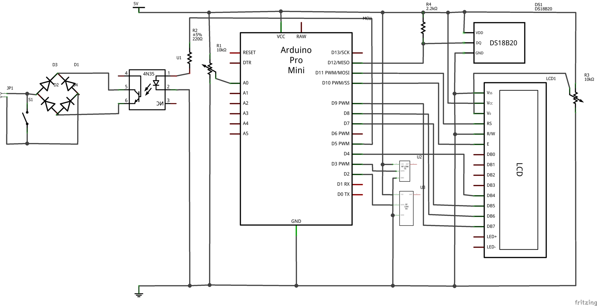
It’s worth starting with the simplest part - the boiler control part. JP1 - connector to which two boiler control lines are connected. S1 - a toggle switch that shorts the boiler control lines and, thus, takes it offline (you never know what happens to the controller). The bridge D1-D4 is needed to ensure polarity tolerance for connection to the boiler. The optocoupler U1 acts as a relay and provides galvanic isolation between the high-voltage boiler control line (recall, when open, this is as much as 42V) and the TTL part of the circuit. R2 is the limiting resistor needed so that the current through the D5 terminal (through which the control is carried out) of the microcontroller is not too large. In principle, this part could be replaced by a low-current relay, but ... In the depths of the soul hope is warming, that the boiler supports OT / + and will be able to manage it in a civilized manner. The real scheme of pairing with the boiler is somewhat more complicated. Here it is described only to the extent necessary for controlling the boiler in the closed / open mode.
The DS18B20 temperature sensor is connected to pin 12 of the microcontroller. A resistor R4 is connected between the data pin of the DS18B20 and the power bus in accordance with the specification.
LCD screen based on the HD44780 controller - two lines of eight characters. The switching circuit is classic: Vcc - to the power bus, Vss - ground, a reference voltage is applied to V0 to adjust the contrast, formed by the divider in the face of the building resistor R3. R3 can be twisted once to taste and forget. The R / W pin is set to ground. The remaining pins are connected as follows: RS-> pin 11 of the controller, Enable -> 10, DB4-> 4, DB5-> 7, DB6-> 8, DB7-> 9.
The receiver is connected to terminal 2, the transmitter to terminal 3.
A0 is connected to a variable resistor forming a divider. Based on the voltage at terminal A0, the firmware of the controller will make a conclusion about the target temperature in the house.
The algorithm of work looks like this:

In general, MK spends time waiting for messages on the air. If no message arrives within the set time, the algorithm still executes the main body (after all, during this time the temperature of the water in the circuit could change and perhaps it was time to turn the burner on or off).
In parallel with this, a voltage measurement is performed on the A0 timer, in accordance with which the target temperature in the house is set. Voltage 0 corresponds to a temperature of 18C, voltage Vcc corresponds to a temperature of 26C. If the temperature changes, i.e. the user is currently turning the knob, the screen is updated, which always displays three parameters: the target temperature in the room, the temperature of the water in the circuit, the target temperature of the water in the circuit at the moment.
The target water temperature in the circuit is
calculated according to the following formula: Trrw = 20 + (Trr-To) + (Tr-Trr) * 30, where
Trrw is the target water temperature in the circuit
Trr is the target temperature in the house
To is the outdoor
temperature Tr is the temperature in the house
As you can see, there is a certain term of shift 20 (heuristically selected), the term OTC (Trr-To) which is greater, the greater the difference between the target temperature in the room and the temperature in the street and the penalty for not reaching the target temperature in the room (Tr-Trr )*thirty.
The implementation of the algorithm is quite trivial, you can understand it by looking at the firmware sketch.
It should be mentioned that working with the screen brought the most problems. I will not describe children's sores, such as improper connection and initialization, but you can mention the problems associated with inaccurate use of the timer. The fact is that the first timer implementations read A0, calculated the temperature and certainly updated the screen. The refresh rate was quite high - 2Hz, and the screen update procedure was quite lengthy. This led to the fact that the main loop of the algorithm (which spends most of the time trying to receive something from the air) was often and for a long time interrupted by the timer handler. This led to the fact that the software part of the receiver could not receive anything from the air, because it missed a lot during the distraction of the timer handler. Moreover, the screen occasionally goes crazy and needs to be reinitialized to bring it back to life. What is the reason for this behavior, I still do not understand.
The second problem I encountered - the first place the controller was installed turned out to be a place of brutal radio shadow.
These two problems robbed me of a decent amount of nights trying to figure out why the controller is not accepting anything. The most opposite is that the elimination of any of them did not improve the situation, it was necessary to solve both at the same time, so for quite some time I was in the misconceptions like “the radio shadow has nothing to do with it” and “everything is in order with the receiving part.
Another very bad idea was the transfer of all controlled parameters in bulk to the radio at each iteration of the algorithm. The parameters transmitted include: the temperature in the room, the temperature in the street (just a repeat for control purposes), the set target temperature in the house, the calculated target value of the water temperature, the current value of the water temperature, whether the boiler control circuit is closed or not. Since the execution of one iteration of the algorithm takes about 30 seconds, a bunch of packets fell into the air twice a minute, which led to an increase in the probability of collisions. Therefore, it was necessary to modify the firmware so that it sent only one parameter to the air in one iteration. Thus, each parameter began to be updated every 3 minutes.
Arduino Pro Mini - 100 rubles apiece
DS18B20 - 34 rubles apiece
Transmitter + receiver 433MHz - 40 rubles apiece
LCD WH0802A-NGG-CT - 125 rubles apiece
4N35 - 9 rubles apiece
DB107 diode bridge - 5.5 rubles apiece
Resistors - just 5 rubles;
Toggle switch (purchased offline) - 20 rubles;
Case KR-606-PS - 40 rubles;
Result - including solder, breadboard, wires and depreciation of the soldering iron - about 450 rubles. If I ordered LCD on Ebay, it would have turned out another 80 rubles cheaper.
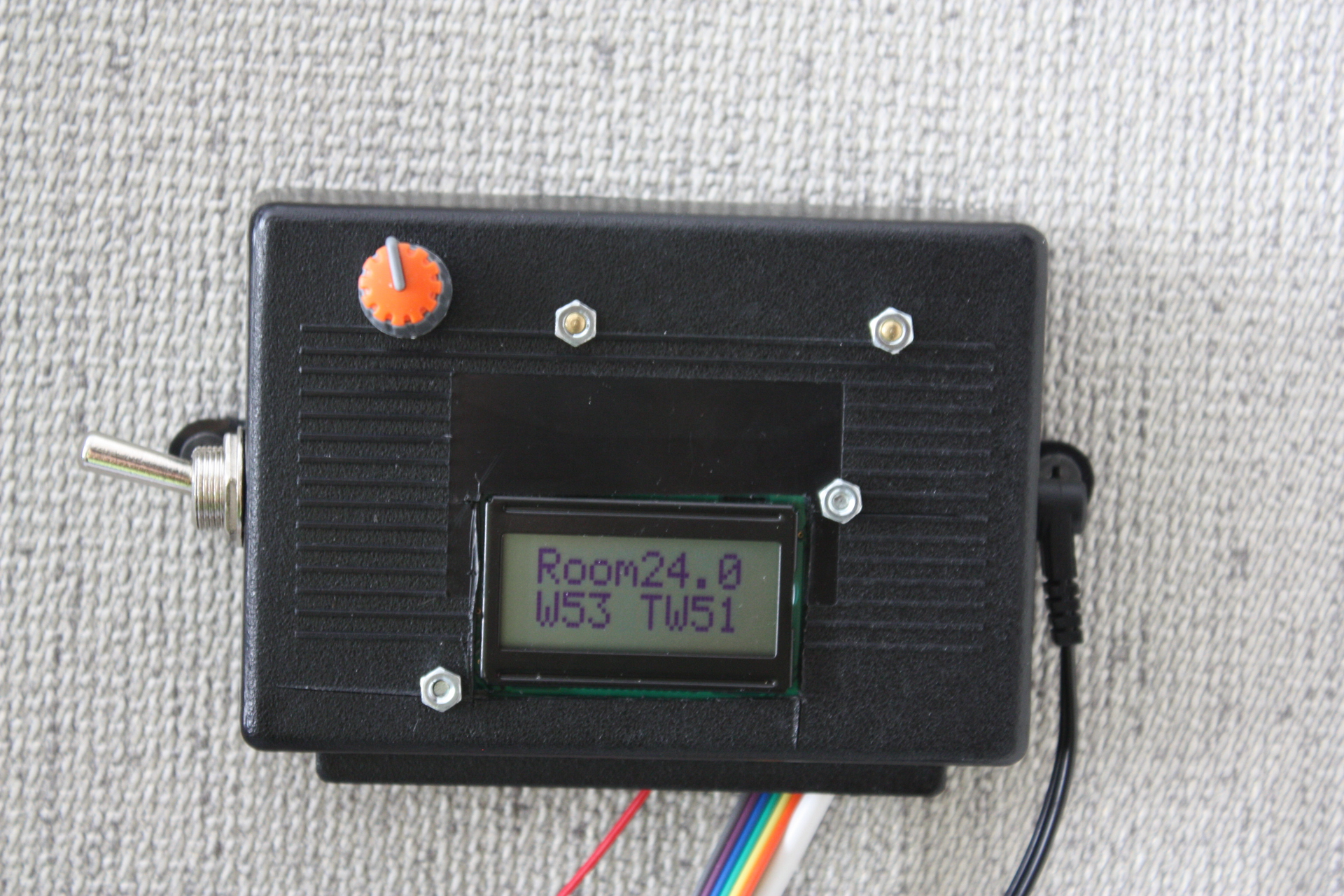
Photos of the controller itself and the boiler under the spoiler. I apologize for the unevenly cut window under the LCD.
But DS18B20 is screwed to the boiler exit
Photo of how the "control panel" looks on the same Strike.
As I said, two control schemes were implemented - classic, i.e. “Not hot enough?” Fry! ”, And with compensation for street temperature.
In principle, the first one met the requirements originally presented to the stating system, i.e. provided room temperature within half a degree of the target value. However, the disadvantage was fluctuations around this target value with an amplitude of almost half a degree. Those. the temperature in the room oscillated around the target, and this oscillation clearly could not be caused by external factors, since they were stable.
But the introduction of OTC gave an unexpected good result. Work according to the algorithm in accordance with the formula above stabilized the temperature within -0.2 + 0.1 degrees from the target. It should be noted that dips of 0.2 degrees are not even related to the peculiarities of the thermal control process, but to the fact that when someone opens hot water (for example, it takes half an hour to wash), the boiler is busy providing hot water in the hot water supply circuit. The heating circuit does not heat up.
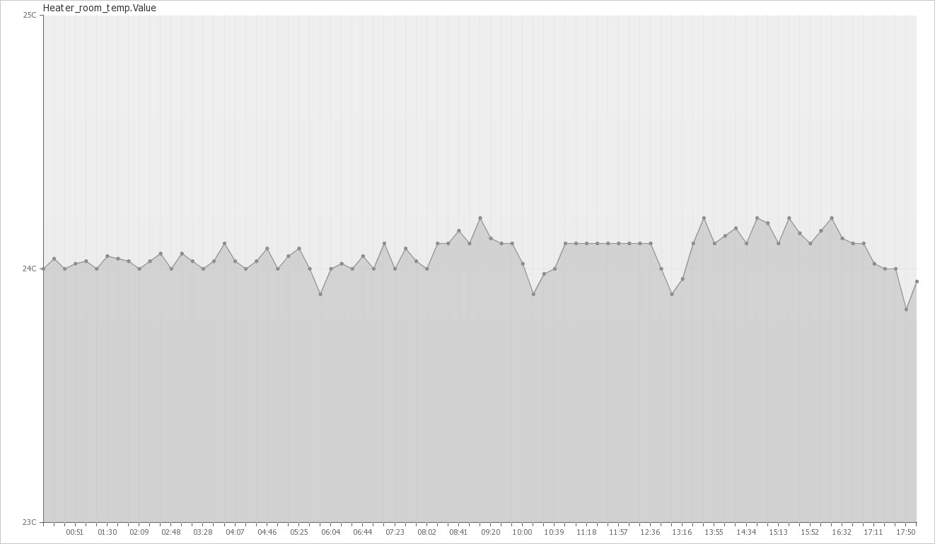
The controller in this mode has been working for half a month, the flight is normal, there were no failures. I can say that thermostating decently increases psychological comfort. If earlier it was necessary to set the water temperature at least every evening and morning in accordance with the current temperature on the street, the forecast and the testimony of our own intuition, which required some efforts, now we do not even remember that we have a boiler - it works for itself and works.
The plans mean to squeeze OT / +, the benefit of the ordered oscilloscope came, with its help I already found out that I even sent it to the side of the boiler (there was a banal typo in the code that I double-checked and didn’t see - my eyes went blurry), but I’m generally silent. In principle, the thermostat will not improve the operation, but will allow you to remove more diagnostics. In addition, this is now a fundamental problem from the category of “who whom”.
Introduction
A modern country house with autonomous heating usually involves a gas boiler. In the most primitive version, heating is controlled in two ways:
- For the task, so to speak, of a general thermophone in the house, the power is set, which the boiler "pumps" into the batteries. Typically, power adjustment is carried out in terms of the temperature of the water after the heating circuit.
- Since the rooms in the house are different (different windows, walls, cardinal points, etc.), they need to be heated in different ways too. In conditions when the heating circuit for the whole house is one, this goal is achieved by adjusting the water supply to the batteries themselves.
At the same time, modern boilers, as a rule, support external control. The main purpose of this feature is to connect various kinds of temperature controllers that allow you to set the boiler power not in abstract degrees of water in the batteries (the same water temperature figures can lead to completely different results depending on external conditions), but in terms of a much more understandable target temperature of the place where the regulator is installed. “Out of band management” can mean anything, but usually it’s either some proprietary protocol of a particular manufacturer of equipment (as, for example, Bosch does), or one of the implementations of the OpenTherm protocol.
The main problem of the mentioned temperature regulators for me is the price. With a boiler cost of about 25,000 rubles, the price of a regulator of 9,000 rubles seems somewhat overpriced.
As a result of bilateral consultations with the toad, an estimate was agreed, one and a half orders of magnitude lower than the cost of a typical commercial regulator, after which the development of options for the implementation of a home-grown regulator began.
The regulator set the following goals:
- It must maintain the target temperature in the place, the temperature sensor of which is selected as the control, with an accuracy of + -0.5 degrees
- It should allow setting the target temperature.
- It should allow monitoring the basic aspects of the regulator and the boiler
Openherm
The study of the possibilities of construction began with the study of the boiler's capabilities for external control. After removing the casing, a connector was found on which a jumper hung. Studying the documentation for the boiler gave us hope that it is the same connector for external control. Here it is necessary to mention the special zeal with which the Russian-language documentation was prepared for my Italian boiler Ferroli. The documentation has a description of the connectors. On the contrary, I was interested in the sacred inscription "Unit of environment." Intuition persistently hinted that this is the work of translators unfamiliar with the subject area, it would be necessary to look for English-language documentation (since they should have been more literally translated into English). After digging out from the Internet PDFs with the English version of the boiler manual, everything became clear, opposite the same connector the text “Room unit” flaunted. There was a little icon, which, with a certain amount of imagination, could be mistaken for the OpenTherm logo. “This is what you need,” I thought, and began to plan brutal experiments on the boiler (it was -25 outside the window, so it was time to burn the heater electronics).
Here you need to make the necessary excursion to OpenTherm. The protocol is neither closed nor open. Not closed because if you have a specification, then no one will chase you. Not open because no one will just give you the protocol specification. Join the OpenTherm Alliance for $$$$$$$, then get access to the body of the protocol. Rummaging in the depths of the Internet, I caught the OT2.2 specification.
At the physical level, OpenTherm are two low-current lines with an open voltage of the order of 42V. The control device, when connected to them, can simultaneously power and control the slave.
The specification defines two protocol levels: OT / + and OT / Lite.
The first is a protocol in the sense in which the majority of people in IT understand this word. Those. this is a certain set of requests and responses that go between the control device (it’s also the master unit, it’s also the room unit, in our case it is the regulator) and the slave (it’s the slave unit, this is the boiler). The protocol is divided into the mandatory part, which includes the commands “turn on / off the burner”, “report the status” and “set the very water temperature after the heating circuit (the parameter is called setpoint)”. Optional - a bunch of others, ranging from the control of the modulation of the flame to the removal of gas flow, pressure and water velocity in the circuit. In this case, the control device controls the change in voltage in these lines, and the slave responds with a change in current.
OT / Lite is a simpler thing. If you are not smart enough to implement OT / +, you can simply generate a PWM signal, according to the duty cycle of which the boiler will control the setpoint installation.
In addition, the specification also defines a test mode in which the lines are short-circuited. In this mode, the boiler heats up until it gets bored (read until the upper bar of the water temperature installed on the boiler itself is reached). So the boiler works without an external regulator (therefore, there was a jumper at the opening).
OpenTherm but not quite
I’ll immediately dispel the intrigue and say that it did not work to steer the boiler over OpenTherm. The interface circuit was assembled and even a library was written that implements a rather significant part of OpenTherm, but the boiler stubbornly refused to switch to OpenTherm control mode and did not respond. More precisely, the microcontroller did not register anything as an answer. The boiler answered or not, it is impossible to say without an oscilloscope. As soon as understanding of this fact came, a USB oscilloscope (aka an eight-channel logic analyzer, aka a USB blaster) was ordered for 40 evergreens (which, I have to say, is just a mega thing!). The oscilloscope, as expected, was supposed to go from China an indefinite time and come somewhere in the spring, when the relevance of thermal control, hmm, is somewhat less than in winter.
How to steer a boiler
The contemplation of the boiler on long winter evenings led to the understanding that the logic of its operation is quite simple. You set the temperature of the water (setpoint), say 55C. It starts to warm until the temperature reaches 60C. Then it turns off and on again when the water temperature reaches 50C. A kind of swing with hysteresis around the set value. Having a "test feature", it is very easy to control the boiler using an external device so that it works exactly the same as without it.
Another consequence of the contemplation of the boiler is the understanding of what temperature of water you need to set on it, depending on the temperature in the street, so that in the house, plus or minus, the bast shoe is comfortable.
So, boiler control consists of two algorithms:
- Burner on-off algorithm depending on the desired setpoint and current water temperature
- Setpoint calculation algorithm based on available temperature data
Here it is necessary to make the necessary digression into the principle of operation of thermostats available on the market. They come in two kinds:
- Classic. The principle of operation - colder than it should be - must be warmed, warmer - no need to warm. The second principle - if it is much colder, you need to warm very much
- The so-called regulators with OTC (outdoor temperature compensation), i.e. outdoor temperature controllers. These are trickier. They allow you to set the dependence of setpoint on the temperature outside. Theoretically, they should steer the temperature in the house more accurately
Since I had temperature data both in rooms and on the street, I, in principle, could implement a device with OTC. In fact, both schemes were tested, and, confirmed by experiments, the second is more profitable.
I want to remind you that as a result of the implementation of the weather station, weather data appeared on the air around my house. The algorithm of the thermostat should be something like this:
- Catch the weather data from the air
- Measure the temperature of the water in the heating circuit
- Based on the available data, calculate the target water temperature in the circuit
- Control the burner to maintain the target water temperature in the circuit
Hardware
The hardware is required to:
- Received data from the air
- Allowed to set the target temperature in the house
- Displayed basic indicators
- She knew how to “shorten the line” of boiler control
- Send data about their work and the operation of the boiler back to the air so that they can be caught by the central unit and then visualized
These requirements are dictated by the scheme.
It’s worth starting with the simplest part - the boiler control part. JP1 - connector to which two boiler control lines are connected. S1 - a toggle switch that shorts the boiler control lines and, thus, takes it offline (you never know what happens to the controller). The bridge D1-D4 is needed to ensure polarity tolerance for connection to the boiler. The optocoupler U1 acts as a relay and provides galvanic isolation between the high-voltage boiler control line (recall, when open, this is as much as 42V) and the TTL part of the circuit. R2 is the limiting resistor needed so that the current through the D5 terminal (through which the control is carried out) of the microcontroller is not too large. In principle, this part could be replaced by a low-current relay, but ... In the depths of the soul hope is warming, that the boiler supports OT / + and will be able to manage it in a civilized manner. The real scheme of pairing with the boiler is somewhat more complicated. Here it is described only to the extent necessary for controlling the boiler in the closed / open mode.
The DS18B20 temperature sensor is connected to pin 12 of the microcontroller. A resistor R4 is connected between the data pin of the DS18B20 and the power bus in accordance with the specification.
LCD screen based on the HD44780 controller - two lines of eight characters. The switching circuit is classic: Vcc - to the power bus, Vss - ground, a reference voltage is applied to V0 to adjust the contrast, formed by the divider in the face of the building resistor R3. R3 can be twisted once to taste and forget. The R / W pin is set to ground. The remaining pins are connected as follows: RS-> pin 11 of the controller, Enable -> 10, DB4-> 4, DB5-> 7, DB6-> 8, DB7-> 9.
The receiver is connected to terminal 2, the transmitter to terminal 3.
A0 is connected to a variable resistor forming a divider. Based on the voltage at terminal A0, the firmware of the controller will make a conclusion about the target temperature in the house.
Software part
The algorithm of work looks like this:
In general, MK spends time waiting for messages on the air. If no message arrives within the set time, the algorithm still executes the main body (after all, during this time the temperature of the water in the circuit could change and perhaps it was time to turn the burner on or off).
In parallel with this, a voltage measurement is performed on the A0 timer, in accordance with which the target temperature in the house is set. Voltage 0 corresponds to a temperature of 18C, voltage Vcc corresponds to a temperature of 26C. If the temperature changes, i.e. the user is currently turning the knob, the screen is updated, which always displays three parameters: the target temperature in the room, the temperature of the water in the circuit, the target temperature of the water in the circuit at the moment.
The target water temperature in the circuit is
calculated according to the following formula: Trrw = 20 + (Trr-To) + (Tr-Trr) * 30, where
Trrw is the target water temperature in the circuit
Trr is the target temperature in the house
To is the outdoor
temperature Tr is the temperature in the house
As you can see, there is a certain term of shift 20 (heuristically selected), the term OTC (Trr-To) which is greater, the greater the difference between the target temperature in the room and the temperature in the street and the penalty for not reaching the target temperature in the room (Tr-Trr )*thirty.
The implementation of the algorithm is quite trivial, you can understand it by looking at the firmware sketch.
Sketch
#include
#include
#include
#include
#include
#include
#include
#define DEBUG
#define INVALID_TEMPERATURE (1000)
/ * hardware configuration * /
#define DSPIN 12
#define TRANSMITPIN 3
#define RECEIVEPIN 2
#define HEATERCONTROLPIN 5
#define TARGETTEMPCONTROLPIN A0
// LCD pin mapping
#define LCDAB 11
#define LCDRS 11
#define LCDD4 4
#define LCDD5 7
#define LCDD6 8
#define LCDD7 9
#define RECEIVETIMEOUT 30 // wireless receive timeout
bool heater_enabled = false;
void enable_heater ()
{
digitalWrite (HEATERCONTROLPIN, HIGH);
heater_enabled = true;
}
void disable_heater ()
{
digitalWrite (HEATERCONTROLPIN, LOW);
heater_enabled = false;
}
float target_room_temperature, previous_target_room_temperature;
/ * reads target room temperature from the potentiometer and returns true if the value changed * /
bool updateTargetRoomTemp ()
{
uint16_t potentiometer_value = analogRead (TARGETTEMPCONTROLPIN);
target_room_temperature = 22 + 4 / 1024.0 * potentiometer_value;
if (fabs (target_room_temperature - previous_target_room_temperature) <0.1)
{
return false;
}
previous_target_room_temperature = target_room_temperature;
return true;
}
uint16_t cycle_counter = 0;
void targetTempChangeChecker ()
{
if (cycle_counter ++% 16 == 0) // max period of timer2 is 16ms, so we throttle out 15 cycles of 16 to update target temp value approx 4 times per second
{
if (updateTargetRoomTemp ())
updateOnScreenInfo ();
}
}
#define OUTSIDE_SENSOR_ID 27327
#define ROOM_SENSOR_ID 13467
#define TEMPERATURE_HYSTERESIS 5
#define HEATER_MAX_TEMP 80
#define HEATER_MIN_TEMP 30
float room_temperature = INVALID_TEMPERATURE;
float outside_temperature = INVALID_TEMPERATURE;
float RW_temperature;
float target_RW_temperature = 30;
OneWire one_wire (DSPIN);
DallasTemperature sensor (& one_wire);
void updateTargetRWTemperature ()
{
sensor.requestTemperatures ();
RW_temperature = sensor.getTempCByIndex (0);
target_RW_temperature = 20 + (target_room_temperature - outside_temperature) + (target_room_temperature - room_temperature) * 30;
target_RW_temperature = min (target_RW_temperature, HEATER_MAX_TEMP);
target_RW_temperature = max (target_RW_temperature, HEATER_MIN_TEMP);
}
LiquidCrystal lcd (LCDRS, LCDENABLE, LCDD4, LCDD5, LCDD6, LCDD7);
void updateOnScreenInfo ()
{
char floatBuffer [7];
lcd.setCursor (0,0);
lcd.print (F ("Room"));
lcd.print (dtostrf (target_room_temperature, 2, 1, floatBuffer));
lcd.setCursor (0,1);
lcd.print (F ("W"));
lcd.print ((int) RW_temperature);
lcd.print (F ("TW"));
lcd.print ((int) target_RW_temperature);
}
WirelessSensorPipe pipe;
void setup ()
{
#ifdef DEBUG
Serial.begin (9600);
Serial.println (F ("Entered setup"));
#endif
pinMode (HEATERCONTROLPIN, OUTPUT);
sensor.begin ();
pipe.begin (TRANSMITPIN, RECEIVEPIN, 13);
#ifdef DEBUG
Serial.print (F ("Sensor id:"));
Serial.println (pipe.id ());
#endif
updateTargetRoomTemp ();
updateTargetRWTemperature ();
TimerTwo :: init (16384, targetTempChangeChecker);
TimerTwo :: start ();
lcd.begin (8, 2);
}
int current_transmission_phase = 0;
void loop ()
{
#ifdef DEBUG
Serial.print (F ("Timestamp:"));
Serial.println (millis () / 1000);
Serial.print (F (“RW temperature:„));
Serial.println (RW_temperature);
Serial.print (F (“target_RW temperature:„));
Serial.println (target_RW_temperature);
Serial.print (F (“outside temperature:„));
Serial.println (outside_temperature);
Serial.print (F (“room temperature:„));
Serial.println (room_temperature);
Serial.print (F (“target room temperature:„));
Serial.println (target_room_temperature);
// blink the LED to indicate that the readings are done
// digitalWrite (13, HIGH);
// delay (100);
// digitalWrite (13, LOW);
#endif
updateTargetRoomTemp ();
lcd.begin (8.2); // periodically LCD goes crazy for some reason, so this is a temporary hack to get off of this state. shall be removed when the reason for such behavior become clear.
lcd.clear ();
updateOnScreenInfo ();
WirelessSensorPipe :: Packet packet;
if (pipe.receive (packet, RECEIVETIMEOUT * 1000))
{
if (packet.type == WirelessSensorPipe :: TEMPERATURE)
{
switch (packet.id)
{
case OUTSIDE_SENSOR_ID:
outside_temperature = packet.value;
break;
case ROOM_SENSOR_ID:
room_temperature = packet.value;
break;
}
}
return; // we skip the rest of the code to avoid sending our data and conflicting with other devices sending data in series. In other words we listen until someone transmits and doing the rest of the work if no one transmits
}
updateTargetRWTemperature ();
if (RW_temperature> = target_RW_temperature + TEMPERATURE_HYSTERESIS && target_RW_temperature <HEATER_MAX_TEMP)
{
disable_heater ();
}
if (RW_temperature <= target_RW_temperature - TEMPERATURE_HYSTERESIS && target_RW_temperature> HEATER_MIN_TEMP)
{
enable_heater ();
}
switch (current_transmission_phase ++)
{
case 0:
pipe.send (WirelessSensorPipe :: TEMPERATURE, room_temperature);
break;
case 1:
pipe.send (WirelessSensorPipe :: HEATERSETPOINT, target_RW_temperature);
break;
case 2:
pipe.send (WirelessSensorPipe :: HEATERRWTEMPERATURE, RW_temperature);
break;
case 3:
pipe.send (WirelessSensorPipe :: HEATERTARGETROOMTEMPERATURE, target_room_temperature);
break;
case 4:
pipe.send (WirelessSensorPipe :: HEATERFLAMEENABLED, heater_enabled);
current_transmission_phase = 0;
break;
}
}
#include
#include
#include
#include
#include
#include
#define DEBUG
#define INVALID_TEMPERATURE (1000)
/ * hardware configuration * /
#define DSPIN 12
#define TRANSMITPIN 3
#define RECEIVEPIN 2
#define HEATERCONTROLPIN 5
#define TARGETTEMPCONTROLPIN A0
// LCD pin mapping
#define LCDAB 11
#define LCDRS 11
#define LCDD4 4
#define LCDD5 7
#define LCDD6 8
#define LCDD7 9
#define RECEIVETIMEOUT 30 // wireless receive timeout
bool heater_enabled = false;
void enable_heater ()
{
digitalWrite (HEATERCONTROLPIN, HIGH);
heater_enabled = true;
}
void disable_heater ()
{
digitalWrite (HEATERCONTROLPIN, LOW);
heater_enabled = false;
}
float target_room_temperature, previous_target_room_temperature;
/ * reads target room temperature from the potentiometer and returns true if the value changed * /
bool updateTargetRoomTemp ()
{
uint16_t potentiometer_value = analogRead (TARGETTEMPCONTROLPIN);
target_room_temperature = 22 + 4 / 1024.0 * potentiometer_value;
if (fabs (target_room_temperature - previous_target_room_temperature) <0.1)
{
return false;
}
previous_target_room_temperature = target_room_temperature;
return true;
}
uint16_t cycle_counter = 0;
void targetTempChangeChecker ()
{
if (cycle_counter ++% 16 == 0) // max period of timer2 is 16ms, so we throttle out 15 cycles of 16 to update target temp value approx 4 times per second
{
if (updateTargetRoomTemp ())
updateOnScreenInfo ();
}
}
#define OUTSIDE_SENSOR_ID 27327
#define ROOM_SENSOR_ID 13467
#define TEMPERATURE_HYSTERESIS 5
#define HEATER_MAX_TEMP 80
#define HEATER_MIN_TEMP 30
float room_temperature = INVALID_TEMPERATURE;
float outside_temperature = INVALID_TEMPERATURE;
float RW_temperature;
float target_RW_temperature = 30;
OneWire one_wire (DSPIN);
DallasTemperature sensor (& one_wire);
void updateTargetRWTemperature ()
{
sensor.requestTemperatures ();
RW_temperature = sensor.getTempCByIndex (0);
target_RW_temperature = 20 + (target_room_temperature - outside_temperature) + (target_room_temperature - room_temperature) * 30;
target_RW_temperature = min (target_RW_temperature, HEATER_MAX_TEMP);
target_RW_temperature = max (target_RW_temperature, HEATER_MIN_TEMP);
}
LiquidCrystal lcd (LCDRS, LCDENABLE, LCDD4, LCDD5, LCDD6, LCDD7);
void updateOnScreenInfo ()
{
char floatBuffer [7];
lcd.setCursor (0,0);
lcd.print (F ("Room"));
lcd.print (dtostrf (target_room_temperature, 2, 1, floatBuffer));
lcd.setCursor (0,1);
lcd.print (F ("W"));
lcd.print ((int) RW_temperature);
lcd.print (F ("TW"));
lcd.print ((int) target_RW_temperature);
}
WirelessSensorPipe pipe;
void setup ()
{
#ifdef DEBUG
Serial.begin (9600);
Serial.println (F ("Entered setup"));
#endif
pinMode (HEATERCONTROLPIN, OUTPUT);
sensor.begin ();
pipe.begin (TRANSMITPIN, RECEIVEPIN, 13);
#ifdef DEBUG
Serial.print (F ("Sensor id:"));
Serial.println (pipe.id ());
#endif
updateTargetRoomTemp ();
updateTargetRWTemperature ();
TimerTwo :: init (16384, targetTempChangeChecker);
TimerTwo :: start ();
lcd.begin (8, 2);
}
int current_transmission_phase = 0;
void loop ()
{
#ifdef DEBUG
Serial.print (F ("Timestamp:"));
Serial.println (millis () / 1000);
Serial.print (F (“RW temperature:„));
Serial.println (RW_temperature);
Serial.print (F (“target_RW temperature:„));
Serial.println (target_RW_temperature);
Serial.print (F (“outside temperature:„));
Serial.println (outside_temperature);
Serial.print (F (“room temperature:„));
Serial.println (room_temperature);
Serial.print (F (“target room temperature:„));
Serial.println (target_room_temperature);
// blink the LED to indicate that the readings are done
// digitalWrite (13, HIGH);
// delay (100);
// digitalWrite (13, LOW);
#endif
updateTargetRoomTemp ();
lcd.begin (8.2); // periodically LCD goes crazy for some reason, so this is a temporary hack to get off of this state. shall be removed when the reason for such behavior become clear.
lcd.clear ();
updateOnScreenInfo ();
WirelessSensorPipe :: Packet packet;
if (pipe.receive (packet, RECEIVETIMEOUT * 1000))
{
if (packet.type == WirelessSensorPipe :: TEMPERATURE)
{
switch (packet.id)
{
case OUTSIDE_SENSOR_ID:
outside_temperature = packet.value;
break;
case ROOM_SENSOR_ID:
room_temperature = packet.value;
break;
}
}
return; // we skip the rest of the code to avoid sending our data and conflicting with other devices sending data in series. In other words we listen until someone transmits and doing the rest of the work if no one transmits
}
updateTargetRWTemperature ();
if (RW_temperature> = target_RW_temperature + TEMPERATURE_HYSTERESIS && target_RW_temperature <HEATER_MAX_TEMP)
{
disable_heater ();
}
if (RW_temperature <= target_RW_temperature - TEMPERATURE_HYSTERESIS && target_RW_temperature> HEATER_MIN_TEMP)
{
enable_heater ();
}
switch (current_transmission_phase ++)
{
case 0:
pipe.send (WirelessSensorPipe :: TEMPERATURE, room_temperature);
break;
case 1:
pipe.send (WirelessSensorPipe :: HEATERSETPOINT, target_RW_temperature);
break;
case 2:
pipe.send (WirelessSensorPipe :: HEATERRWTEMPERATURE, RW_temperature);
break;
case 3:
pipe.send (WirelessSensorPipe :: HEATERTARGETROOMTEMPERATURE, target_room_temperature);
break;
case 4:
pipe.send (WirelessSensorPipe :: HEATERFLAMEENABLED, heater_enabled);
current_transmission_phase = 0;
break;
}
}
It should be mentioned that working with the screen brought the most problems. I will not describe children's sores, such as improper connection and initialization, but you can mention the problems associated with inaccurate use of the timer. The fact is that the first timer implementations read A0, calculated the temperature and certainly updated the screen. The refresh rate was quite high - 2Hz, and the screen update procedure was quite lengthy. This led to the fact that the main loop of the algorithm (which spends most of the time trying to receive something from the air) was often and for a long time interrupted by the timer handler. This led to the fact that the software part of the receiver could not receive anything from the air, because it missed a lot during the distraction of the timer handler. Moreover, the screen occasionally goes crazy and needs to be reinitialized to bring it back to life. What is the reason for this behavior, I still do not understand.
The second problem I encountered - the first place the controller was installed turned out to be a place of brutal radio shadow.
These two problems robbed me of a decent amount of nights trying to figure out why the controller is not accepting anything. The most opposite is that the elimination of any of them did not improve the situation, it was necessary to solve both at the same time, so for quite some time I was in the misconceptions like “the radio shadow has nothing to do with it” and “everything is in order with the receiving part.
Another very bad idea was the transfer of all controlled parameters in bulk to the radio at each iteration of the algorithm. The parameters transmitted include: the temperature in the room, the temperature in the street (just a repeat for control purposes), the set target temperature in the house, the calculated target value of the water temperature, the current value of the water temperature, whether the boiler control circuit is closed or not. Since the execution of one iteration of the algorithm takes about 30 seconds, a bunch of packets fell into the air twice a minute, which led to an increase in the probability of collisions. Therefore, it was necessary to modify the firmware so that it sent only one parameter to the air in one iteration. Thus, each parameter began to be updated every 3 minutes.
Part list
Arduino Pro Mini - 100 rubles apiece
DS18B20 - 34 rubles apiece
Transmitter + receiver 433MHz - 40 rubles apiece
LCD WH0802A-NGG-CT - 125 rubles apiece
4N35 - 9 rubles apiece
DB107 diode bridge - 5.5 rubles apiece
Resistors - just 5 rubles;
Toggle switch (purchased offline) - 20 rubles;
Case KR-606-PS - 40 rubles;
Result - including solder, breadboard, wires and depreciation of the soldering iron - about 450 rubles. If I ordered LCD on Ebay, it would have turned out another 80 rubles cheaper.
Testing, conclusions, plans
Photos of the controller itself and the boiler under the spoiler. I apologize for the unevenly cut window under the LCD.
A photo
But DS18B20 is screwed to the boiler exit
A photo
Photo of how the "control panel" looks on the same Strike.
A photo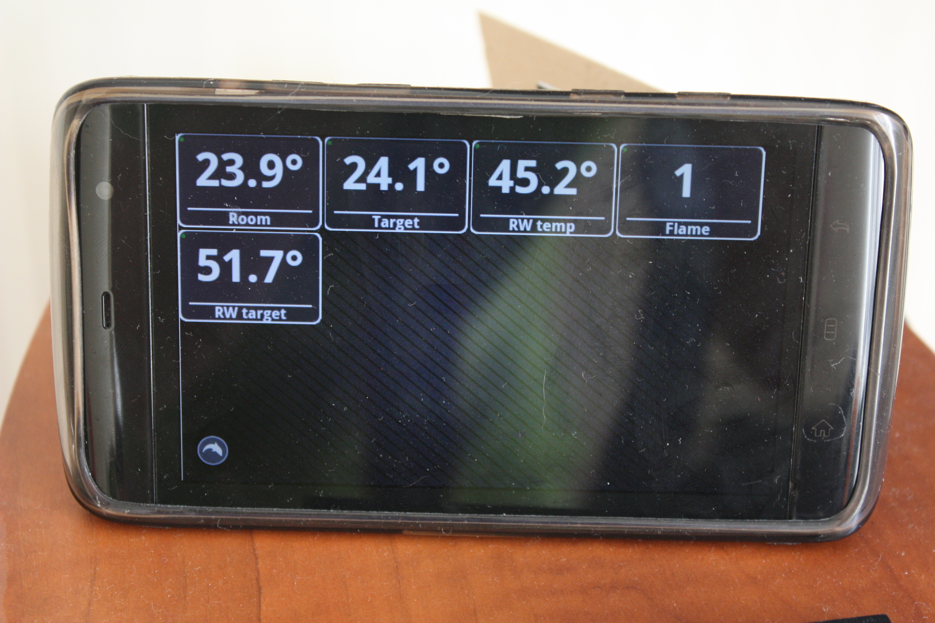
As I said, two control schemes were implemented - classic, i.e. “Not hot enough?” Fry! ”, And with compensation for street temperature.
In principle, the first one met the requirements originally presented to the stating system, i.e. provided room temperature within half a degree of the target value. However, the disadvantage was fluctuations around this target value with an amplitude of almost half a degree. Those. the temperature in the room oscillated around the target, and this oscillation clearly could not be caused by external factors, since they were stable.
But the introduction of OTC gave an unexpected good result. Work according to the algorithm in accordance with the formula above stabilized the temperature within -0.2 + 0.1 degrees from the target. It should be noted that dips of 0.2 degrees are not even related to the peculiarities of the thermal control process, but to the fact that when someone opens hot water (for example, it takes half an hour to wash), the boiler is busy providing hot water in the hot water supply circuit. The heating circuit does not heat up.
The controller in this mode has been working for half a month, the flight is normal, there were no failures. I can say that thermostating decently increases psychological comfort. If earlier it was necessary to set the water temperature at least every evening and morning in accordance with the current temperature on the street, the forecast and the testimony of our own intuition, which required some efforts, now we do not even remember that we have a boiler - it works for itself and works.
The plans mean to squeeze OT / +, the benefit of the ordered oscilloscope came, with its help I already found out that I even sent it to the side of the boiler (there was a banal typo in the code that I double-checked and didn’t see - my eyes went blurry), but I’m generally silent. In principle, the thermostat will not improve the operation, but will allow you to remove more diagnostics. In addition, this is now a fundamental problem from the category of “who whom”.