Interesting and informative: the Breeze-M overclocking unit
- Tutorial

A good reaction to the first post about the Orbiter space simulator and at least two hundred people who became interested and downloaded add-ons for it led me to the idea of continuing the cycle of educational and gaming-oriented posts. Also, I want to facilitate the transition from the first post, in which automation does everything, without requiring your actions, to independent experiments, so as not to get anecdote about drawing an owl . This post has the following goals:
- To tell about the Breeze overclocking family
- To give an idea of the main parameters of the orbital motion: apocenter, pericenter, orbital inclination
- To give an idea of the basics of orbital mechanics and launches into geostationary orbit (GSO)
- Provide a simple guide for mastering the manual exit to GSO in the simulator
Introduction
They do not think much about this, but the Breeze acceleration block family - Breeze-M, Breeze-KM - is an example of an apparatus developed after the collapse of the USSR. There were several reasons for this development:
- On the basis of the UR-100 ICBM, the Rokot conversion launch vehicle was developed, for which an accelerating block (RB) would be useful.
- At Proton, the DM RB was used to launch to the GSO, which used the oxygen-kerosene pair that was not native to Proton, had an autonomous flight time of only 7 hours, and its load capacity could be increased.
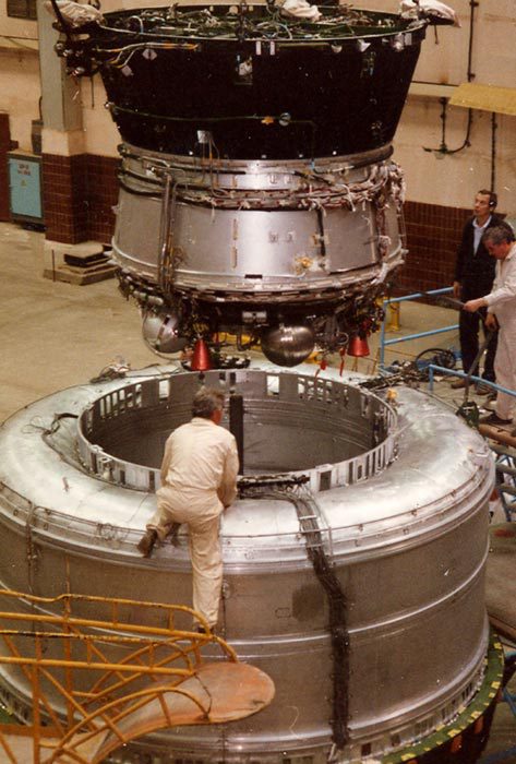
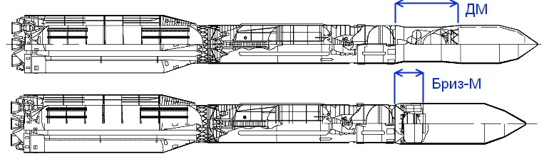
In 1990-1994, test launches took place and, in May-June 2000, flights of both modifications “Breeze” - “Breeze-KM” for “Rokot” and “Breeze-M” for “Proton” took place. The main difference between them is the presence of additional discharged fuel tanks on the Breeze-M, which provide a larger margin of characteristic speed (delta-V) and allow the output of heavier satellites. Here is a photograph that illustrates the difference very well:
Design
Blocks of the Breeze family are distinguished by a very dense layout:
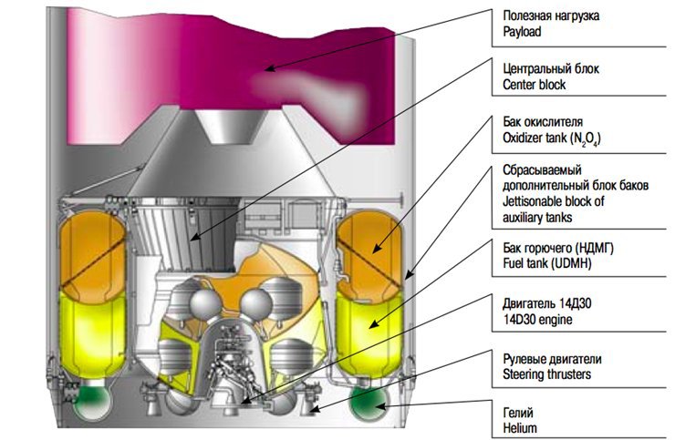
More detailed drawing
Pay attention to technical solutions:
- The engine is inside the "glass" in the tank
- There are also helium cylinders for boosting inside the tanks
- The fuel and oxidizer tanks have a common wall (due to the use of the UDMH / AT pair this does not present technical difficulty), there is no increase in the length of the unit due to the inter-tank compartment
- Tanks are load-bearing - there are no power farms that would require additional weight and increase the length
- Dumped tanks are actually half the stage, which, on the one hand, requires extra weight on the walls, on the other hand, allows you to increase the characteristic speed reserve by dumping empty tanks.
The tight layout saves geometric dimensions and weight, but it also has its drawbacks. For example, an engine that, when working, emits heat, is very close to tanks and pipelines. And the combination of a higher (by 1-2 degrees, within the specification) fuel temperature with a higher thermal stress of the engine during operation (also within the specification) led to the boiling of the oxidizer, impaired cooling of the TNA turbine by a liquid oxidizer and its malfunction, which caused accident of Belarus during the launch of the Yamal-402 satellite in December 2012 .
As RB engines, a combination of three types of engines is used: marching C5.98 (14D30) with a thrust of 2 tons, four correction engines (actually these are sedimentation engines, ullage motors), which are turned on before starting the marching engine to deposit fuel to the bottom of the tanks, and twelve orientation engines with a thrust of 1.3 kg. The main engine has very high parameters (pressure in the combustion chamber ~ 100 atm, specific impulse 328.6 s) despite the open circuit. His “fathers” stood at the Martian stations “Phobos” and “grandfathers” stood at the lunar landing stations of the “Luna-16” type. The main engine can be guaranteed to turn on up to eight times, and the active life of the unit is at least 24 hours.
The mass of a fully charged unit is up to 22.5 tons, the payload reaches 6 tons. But the total mass of the block after separation from the third stage of the launch vehicle is slightly less than 26 tons. During the launch to the geo-transitional orbit, the RB is refueling, and a fully filled tank for direct output to the GSO displayed a maximum of 3.7 tons of payload. The thrust-to - weight ratio of the block is equal to ~ 0.76. This is a disadvantage of RB "Breeze", but small. The fact is that after the separation of RB + PNare in open orbit, which requires an impulse to add, and a small thrust of the engine leads to gravitational losses. Gravity loss is about 1-2%, which is very small. Also, long periods of engine operation increase reliability requirements. On the other hand, the sustainer engine has a guaranteed life of up to 3200 seconds (almost an hour!).
A bit about reliability
The family of RB "Breeze" is operated very actively:
- 4 flights "Breeze-M" on the "Proton-K"
- 72 flights of Breeze-M to Proton-M
- 16 “Breeze-KM” flights on “Rokot”
Total 92 flights on February 16, 2014. Of these, 5 accidents occurred (I recorded a partial success with Yamal-402) due to the fault of the Breeze-M unit and 2 to the fault of the Breeze-KM, which gives us a reliability of 92%. Consider the causes of accidents in more detail:
- February 28, 2006, ArabSat 4A - premature engine shutdown due to an extraneous particle entering the turbine nozzle ( source 1 , source 2 ), a single manufacturing defect.
- March 15, 2008, AMC-14 - premature engine shutdown, destruction of a high-temperature gas pipeline ( source ), its completion was required.
- August 18, 2011, Express-AM4. Unreasonably “narrowed” the time interval of the gyro-stabilized platform turnaround, incorrect orientation ( source ), error of programmers.
- August 6, 2012, Telkom 3, Express-MD2. Engine shutdown due to clogging of the boost line ( source ), manufacturing defect.
- December 9, 2012, Yamal-402. Engine shutdown due to failure of the TNA, a combination of adverse factors in the temperature regime ( source )
- October 8, 2005, Breeze-KM, Cryosat, non-separation of the second stage and RB, abnormal work of software ( source ), error of programmers.
- February 1, 2011, Breeze-KM, Geo-IK2, an abnormal engine pulse, presumably due to a failure of the control system, due to the lack of telemetry, it is impossible to establish the exact reason.
If we analyze the causes of accidents, then only two problems are associated with design problems and design errors - burnout of the gas pipeline and violation of TNA cooling. All other accidents, the cause of which is reliably known, are associated with problems of production quality and preparation for launch. This is not surprising - the space industry requires a very high quality of work, and the mistake of even an ordinary employee can lead to an accident. The Breeze itself is not an unsuccessful design, however, it is worth noting the lack of safety margin due to the fact that to ensure maximum RB characteristics, materials work close to the border of their physical strength.
Flying
It’s time to move on to practice - to manually go into a geostationary orbit in Orbiter. For this we need:
Orbiter release, if you have not downloaded it after reading the first post, here is the link .
Addon "Proton LV" download from here
Bit of theory
Of all the parameters of the orbit, here we will be interested in three parameters: the pericenter height (perigee for the Earth), apocenter height (apogee for the Earth) and inclination:
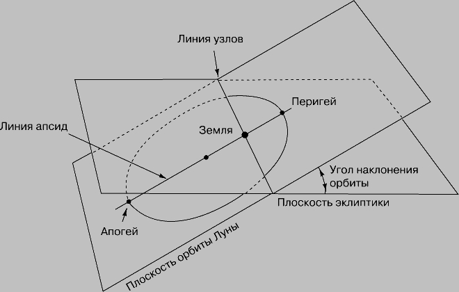
- The height of the apocenter is the height of the highest point in the orbit, denoted by On.
- The height of the pericenter is the height of the lowest point of the orbit, denoted as Hp.
- The inclination of the orbit is the angle between the plane of the orbit and the plane passing through the equator of the Earth (in our case, the orbits around the Earth), is denoted as i .
Geostationary orbit is a circular orbit with a height of the pericenter and apocenter of 35,786 km above sea level and an inclination of 0 degrees. Accordingly, our task is divided into the following stages: to enter a low Earth orbit, raise the apocenter to 35,700 km, change the inclination to 0 degrees, raise the pericenter to 35,700 km. Changing the inclination of the orbit is more advantageous in the apocenter, because there the satellite’s speed is lower, and the lower the speed, the lower delta-V must be applied to change it. One of the tricks of orbital mechanics is that sometimes it is more profitable to raise the apocenter much higher than necessary, change the inclination there, and later lower the apocenter to the desired. The costs of raising and lowering the apocenter above the desired + change in inclination may be less than changing the inclination at the height of the desired apocenter.
Flight plan
In the Breeze-M scenario, Sirius-4, a Swedish communications satellite launched in 2007, is to be launched. Over the years, it has already been renamed, now it is Astra-4A . The plan for its launch was as follows:

It is clear that when we enter the orbit manually, we lose the accuracy of the machines performing ballistic calculations, so our flight parameters will be with rather big errors, but this is not scary.
Stage 1. Entrance to the reference orbit
Stage 1 takes time from launching the program to entering a circular orbit with an altitude of approximately 170 km and an inclination of 51 degrees (a heavy legacy of the Baikonur latitude, at launch from the equator it would be immediately 0 degrees).
Script Proton LV / Proton M / Proton M - Breeze M (Sirius 4)

From loading the simulator to separating the RB from the third stage, you can admire the views - everything is done by automation. Is it necessary to switch the focus of the camera to a rocket from a view from the ground (press F2 to the values from the top left to absolute direction or global frame ).
In the process of displaying, I recommend switching to the “inside” view of F1 , preparing for what awaits us:
By the way, in Orbiter, you can enable a pause forCtrl-P , this may come in handy.
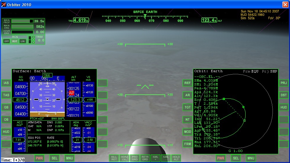
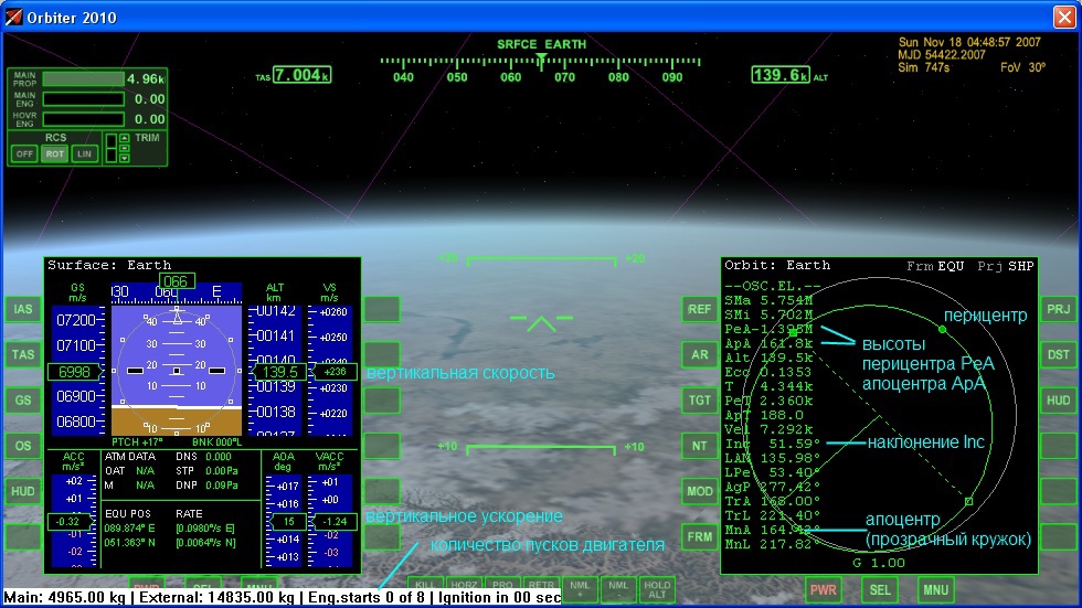
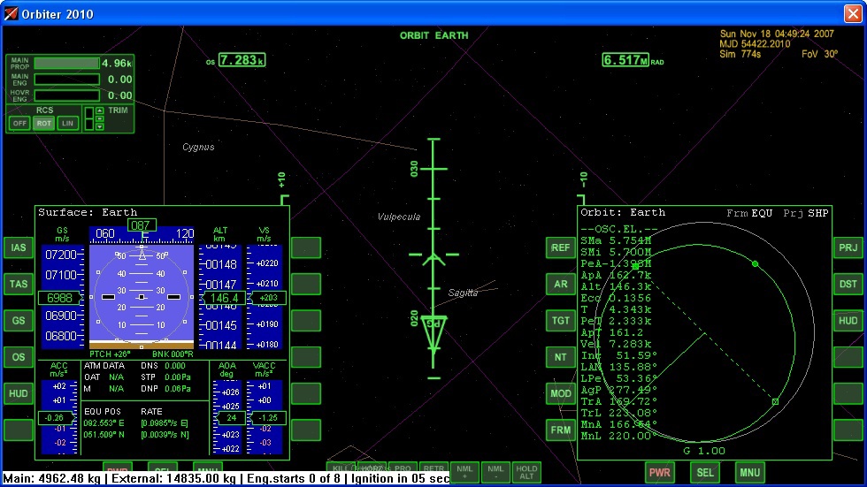
A few explanations about the values of indicators that are important to us:
After separation of the third stage, we find ourselves in an open orbit with the threat of falling into the Pacific, if we act slowly or incorrectly. In order to avoid such a sad fate, we should go into a reference orbit, for which we should:
- Stop the rotation of the block by pressing the Num 5 button . T.N. KillRot mode (rotation stop). After fixing the position, the mode automatically turns off.
- Switch the back view to the front view with the C button .
- Switch the windshield indicator to orbital mode (Orbit Earth from above) by pressing the H button .
- Use the keys Num 2 (turn up), Num 8 (turn down), Num 1 (turn left), Num 3 (turn right), Num 4 (roll left), Num 6 (roll right) and Num 5 (stop rotation) block in the direction of travel with a pitch angle of approximately 22 degrees and lock the position.
- Start the engine start procedure (first Num + , then, without releasing, Ctrl ).
If you do everything right, the picture will be something like this:
After turning on the engine:
- Create a rotation that fixes the pitch angle (a couple of clicks of Num 8 and the angle will not change noticeably).
- In the process of engine operation, keep the pitch angle in the range of 25-30 degrees.
- When the pericenter and apocenter values are around 160-170 km, turn off the engine with the Num * button .
If everything went well, there will be something like:

The most nervous part is over, we are in orbit, nowhere to fall.
Stage 2. Entrance into the intermediate orbit
Due to the low thrust-to-weight ratio, the apocenter has to be raised up to 35,700 km in two stages. The first stage is access to an intermediate orbit with an apocenter of ~ 5000 km. The specifics of the problem - it is necessary to accelerate so that the apocenter does not appear to be away from the equator, i.e. it is necessary to accelerate symmetrically relative to the equator. This will help us with the projection of the scheme of displaying on a map of the Earth:
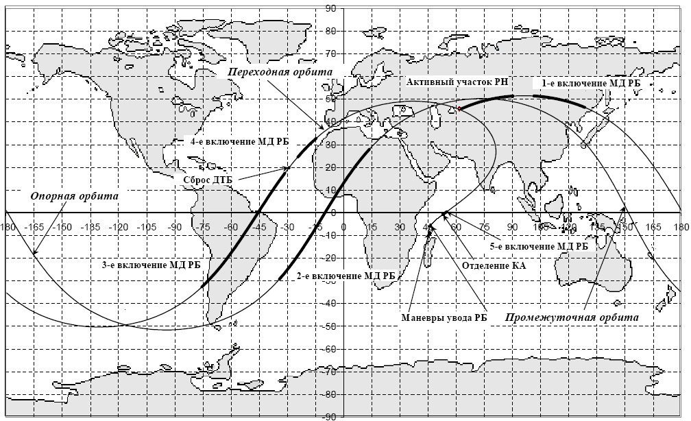
The picture for the recently launched Turksat 4A, but it does not matter.
Preparing to enter the intermediate orbit:
- Switch the left multifunction display to map mode ( Left Shift F1 , Left Shift M ).
- With the help of time acceleration (accelerate by 10 times R , slow down by 10 times T ), wait until the flight over South America.
- Orient the block in position according to the vector of orbital speed (nose in the direction of movement). You can click the [ button so that the automation does it, but here it is not very effective, it’s better manually.
- Give the block a downward rotation to maintain orientation along the orbital velocity vector.
It should turn out something like:

In the area of latitude 27 degrees, you must turn on the engine, and, keeping the orientation along the vector of orbital speed, fly until the apocenter reaches 5000 km. You can enable 10x acceleration. Upon reaching the apocenter 5000 km, turn off the engine.
Music, in my opinion, is very suitable for overclocking in orbit
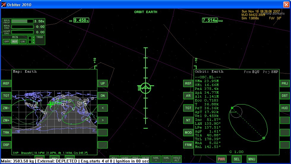
If everything went well, then we get something like:

Stage 3. Entrance into transitional orbit
Very similar to step 2:
- With the help of time acceleration (accelerate by 10 times R , decelerate by 10 times T , you can calmly accelerate to 100x, I don’t advise 1000x) wait until the flight over South America.
- Orient the block in position according to the vector of orbital speed (nose in the direction of movement).
- Give the block a downward rotation to maintain orientation along the orbital velocity vector.
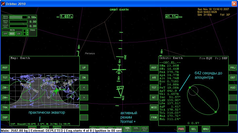
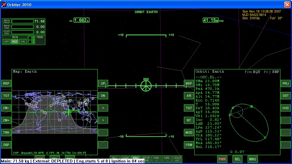
- In the area of latitude 27 degrees, it is necessary to turn on the engine, and while holding stabilization along the vector of orbital speed, fly until the apocenter reaches 35700 km. You can enable 10x acceleration.
- When the fuel is over, reset by pressing in an external fuel tank D . Start the engine again.
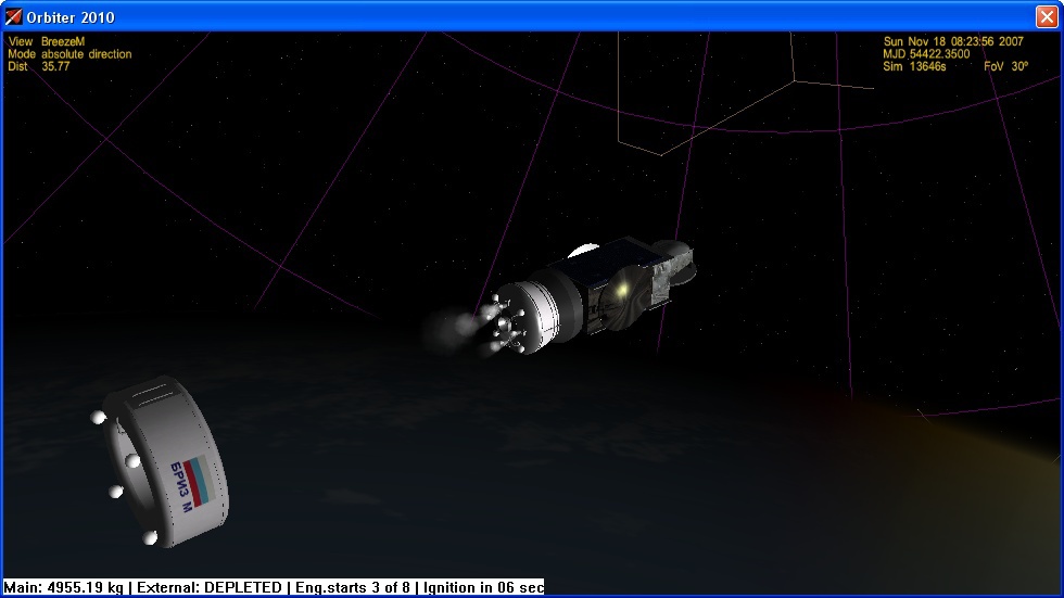
Reset fuel tank, deposition engine operation visible
. Result. Please note, I hurried to turn off the engine, apocenter 34.7 thousand km. This is not scary; for the purity of the experiment we leave it like this.
Beautiful view
Stage 4. Changing the inclination of the orbit
If you did everything with minor errors, then the apocenter will be in the equator region. Procedure:
- Speeding up the time to 1000x, wait for the approach to the equator.
- Orient the block perpendicular to the flight, upward, when viewed from the outside of the orbit. For this, the automatic Nml + mode is suitable, which is activated by pressing a button ; (she's Well )
- Turn on the engine.
- If fuel remains after the maneuver to zero the inclination, you can spend it on raising the pericenter.
- After the fuel has ended, use the J button to separate the satellite, open its solar panels and antennas Alt-A , Alt-S
Starting position before maneuver
After maneuver
Stage 5. Independent satellite launch at GSO
The satellite has an engine with which you can raise the pericenter. To do this, in the area of the apocenter, we orient the satellite along the orbital velocity vector and turn on the engine. The engine is weak, it must be repeated several times. If you do everything right, the satellite will still have about 20% of the fuel for correcting perturbations of the orbit. In reality, the influence of the moon and other factors leads to the satellite’s orbit being distorted, and it is necessary to spend fuel to maintain the required parameters.
If everything worked out for you, the picture will be something like the following:
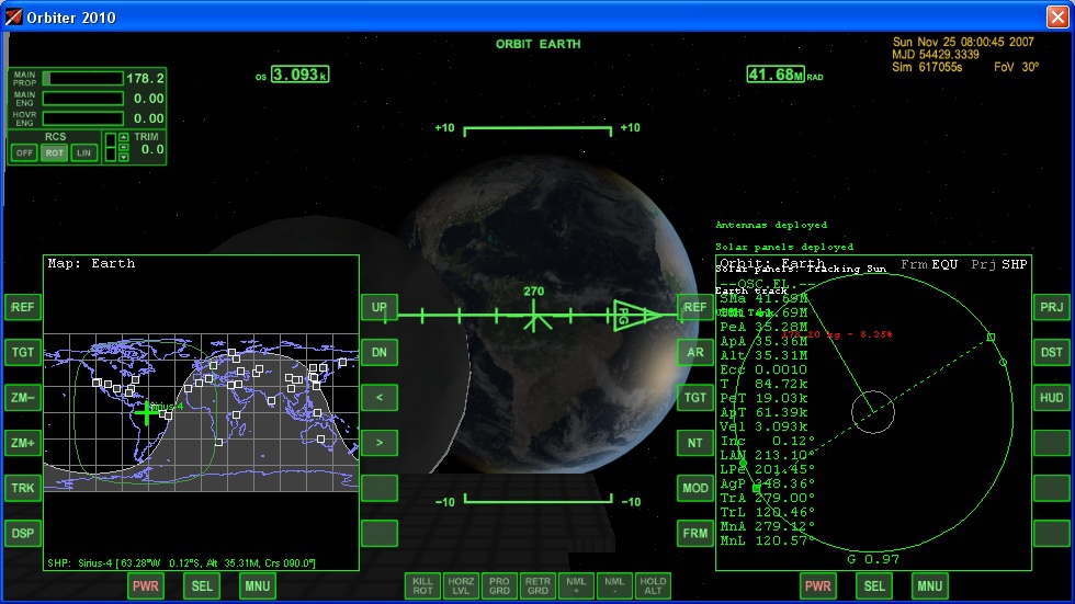
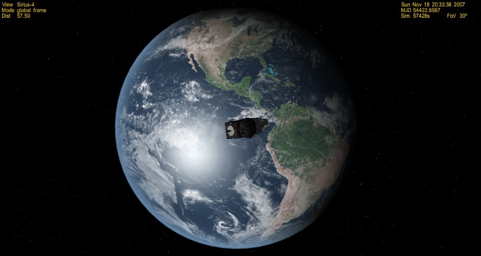
Well, a small illustration of the fact that the satellite on the GSO is located above one place on Earth:
Launcher Turksat 4A, for comparison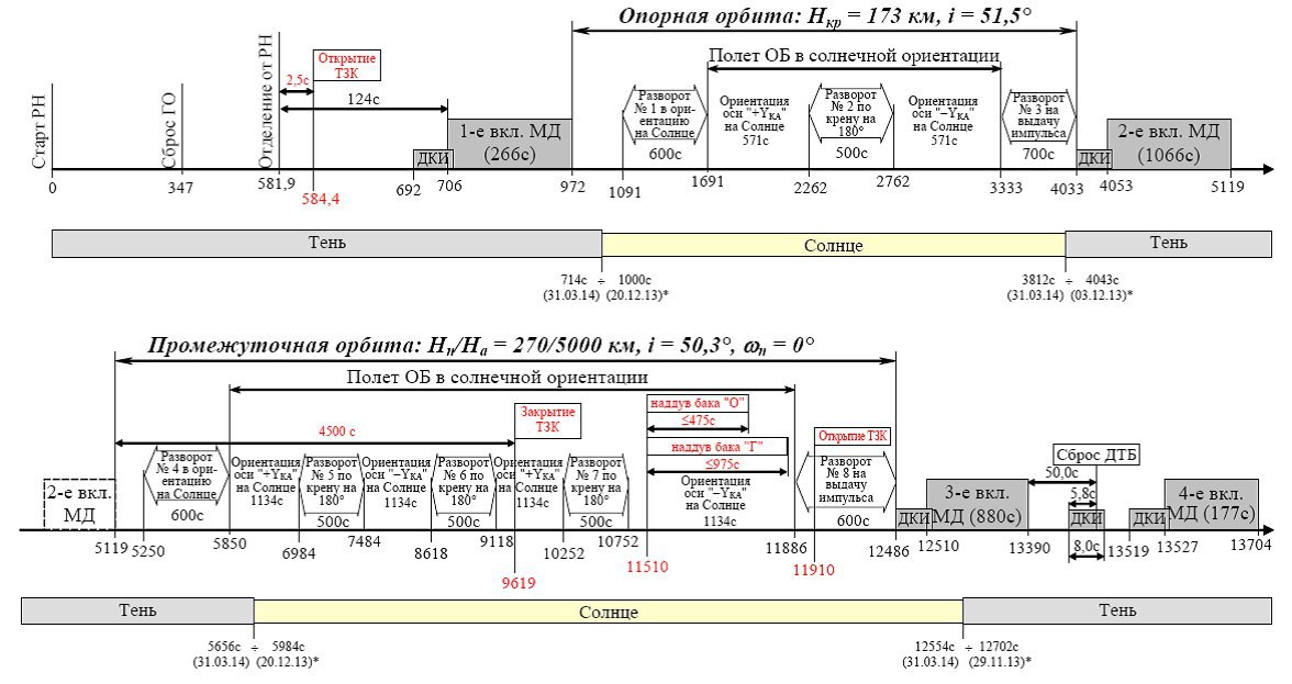

UPD : after consulting aykSpace , I replaced the ugly home-made tracing-paper from Orbiter Prograde / Retrograde with the really existing term “against / against the orbital velocity vector”
UPD2 : I was contacted by a payload adaptation specialist for the Breeze-M GKNPTs im. Khrunicheva, added a couple of comments to the article:
- In reality, not 28 tons, but slightly less than 26, are actually displayed on the suborbital trajectory (the beginning of stage 1), because RBs are not completely filled.
- Gravity loss is only 1-2%