"Plant" radio-controlled sockets without remote control
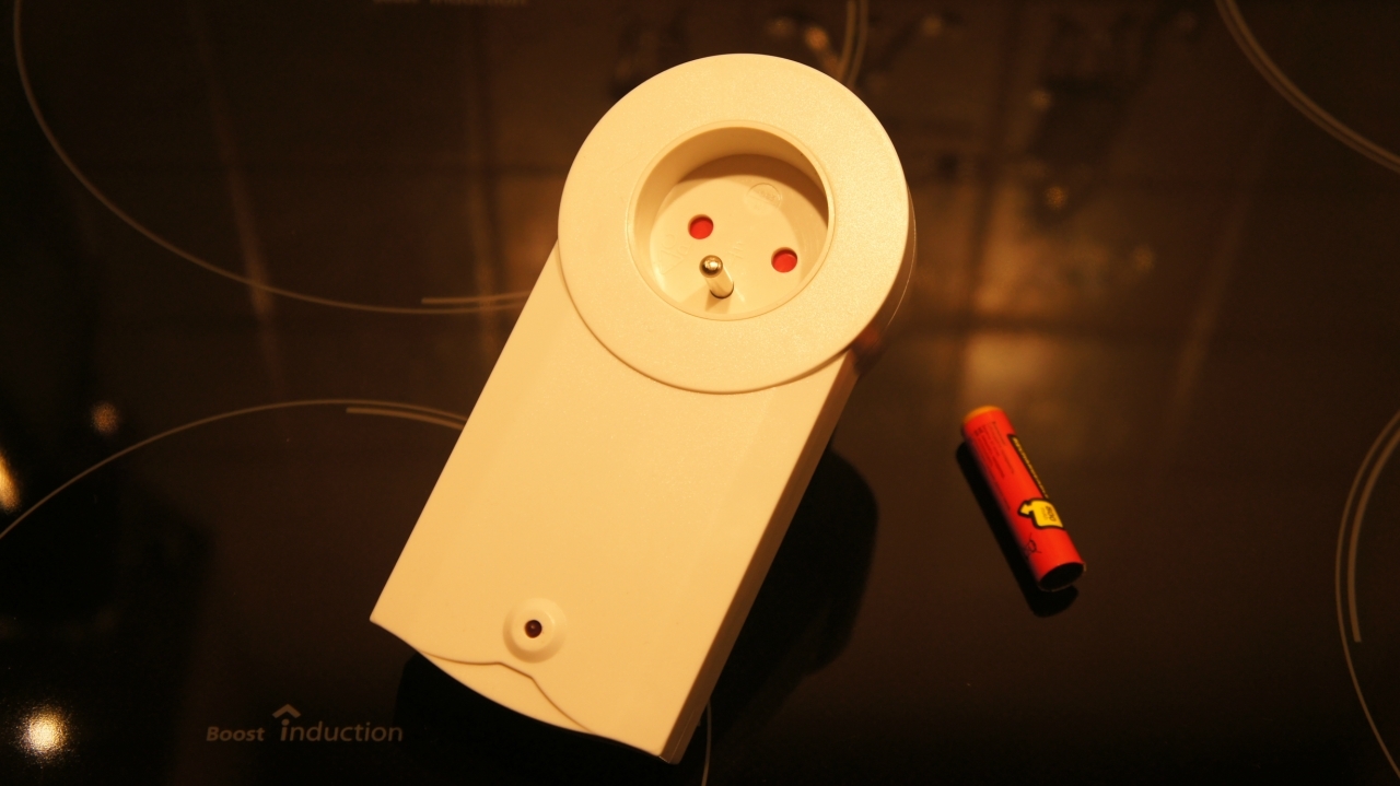
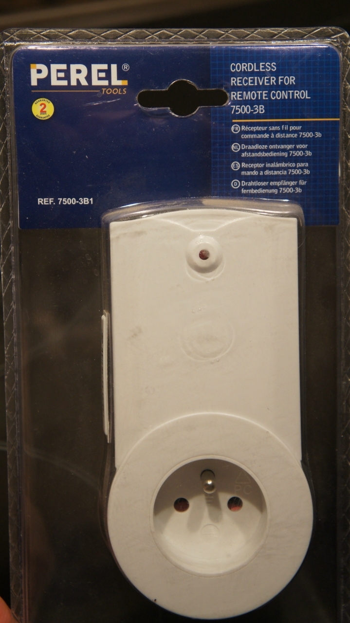
Quite by chance I stumbled upon an attraction of unprecedented generosity in the Ch-i-D catalog. Now additional wireless sockets for the Velleman 7500-3B kit cost only 100 rubles apiece. But this is a socket without a remote control, that is, with somewhat unclear prospects for its use, since before opening it is not very clear what is inside, but there is no sample control codes. If laid on the remote control, then the proposal immediately ceases to be so interesting.
Despite some risk (although there are a hundred rubles ?!), it became interesting how this product, and in this particular configuration, will help the socialist revolution on the scale of a single household.
Before shopping, I was theoretically savvy. That is - I looked for what is in this our Internet on the topic of these outlets. And he practically calmed down when he found out that they are compatible (Velleman WRS3B) with the RC-Switch library , which I have been using for a long time in the home controller to control sockets, execute commands on radio remote control signals and exchange data with peripherals.
This inspired hope.
. such packaging
Short introduction
Typically, sockets (and remotes) of this type are performed on specialized encoding and decoding chips of the 2262/2272 family. Moreover, before the numbers there can be completely different indices: PT, SC, HS. And the indices after the numbers determine the operation mode and configuration of the address and data lines. And most often chips with 8 bits of address and 4 bits of data are used, although options are possible - up to 12 bits of address or up to 6 bits of data.
Within the framework of the protocol used, a bit can take one of three values: 1, 0, and F. Together, the address and data bits (12 bits in total) make up a code word, which is repeated 4 times for reliability, which, respectively, represents one frame. To be honest, the problem is that even reading the datasheets did not bring me closer to understanding what order the bits are in the code word, and what is meant by the mysterious state F.
So from two hours of reading I got about the following.
The basic principle of operation is that for transmitting a command in the transmitter (encoder) and receiver (decoder) the same address is set, and control is carried out, as a rule, via data lines. That is, for each button on the remote control there is one, presumably unique, address.
A typical implementation also includes two bits of data, which say what you need to do with the peripherals at a specific address - enable or disable.
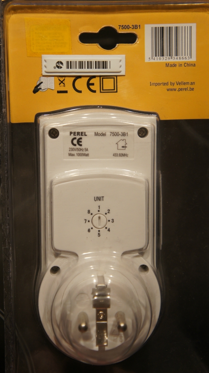
. flip side
Rich inner world
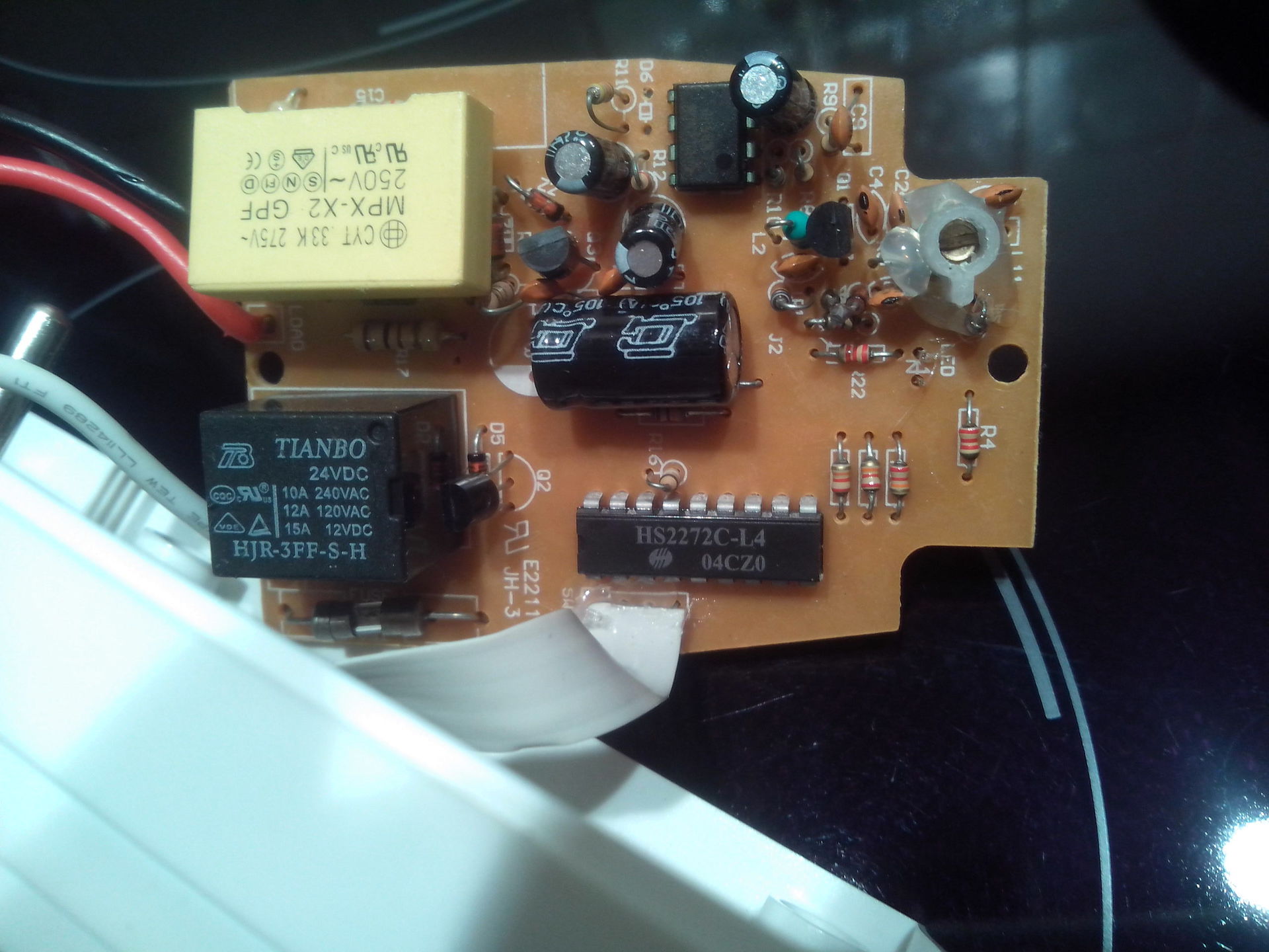
Opening the object, fortunately, lived up to the hope of the popular chip of the 2272 family. More precisely, the HS2272-L4 ( one and two ), which means encoding with 8 address bits, 4 data bits and state fixation. Those. There are two static state change commands for each address. In the case of a socket, this means that we turn it on with one button, and turn it off with the other.
Unlike my radio outlets, there are not 4 channels, but 8 as many - there is where to take a walk. Changing channels is implemented using, so to speak, a hardware converter from decimal to binary.
. the plastic is soft, the encoder is hard, the marker pointer of the socket is almost imperceptible. I had to tint with a felt-tip pen.

The encoder is a rotary sleeve with “mustache” contacts and its counterpart is a board with a pattern of tracks, the closure of which “mustache” determines the state of three of the 8 bits of the address. It is easy to guess that it is these three bits that determine 8 control channels.
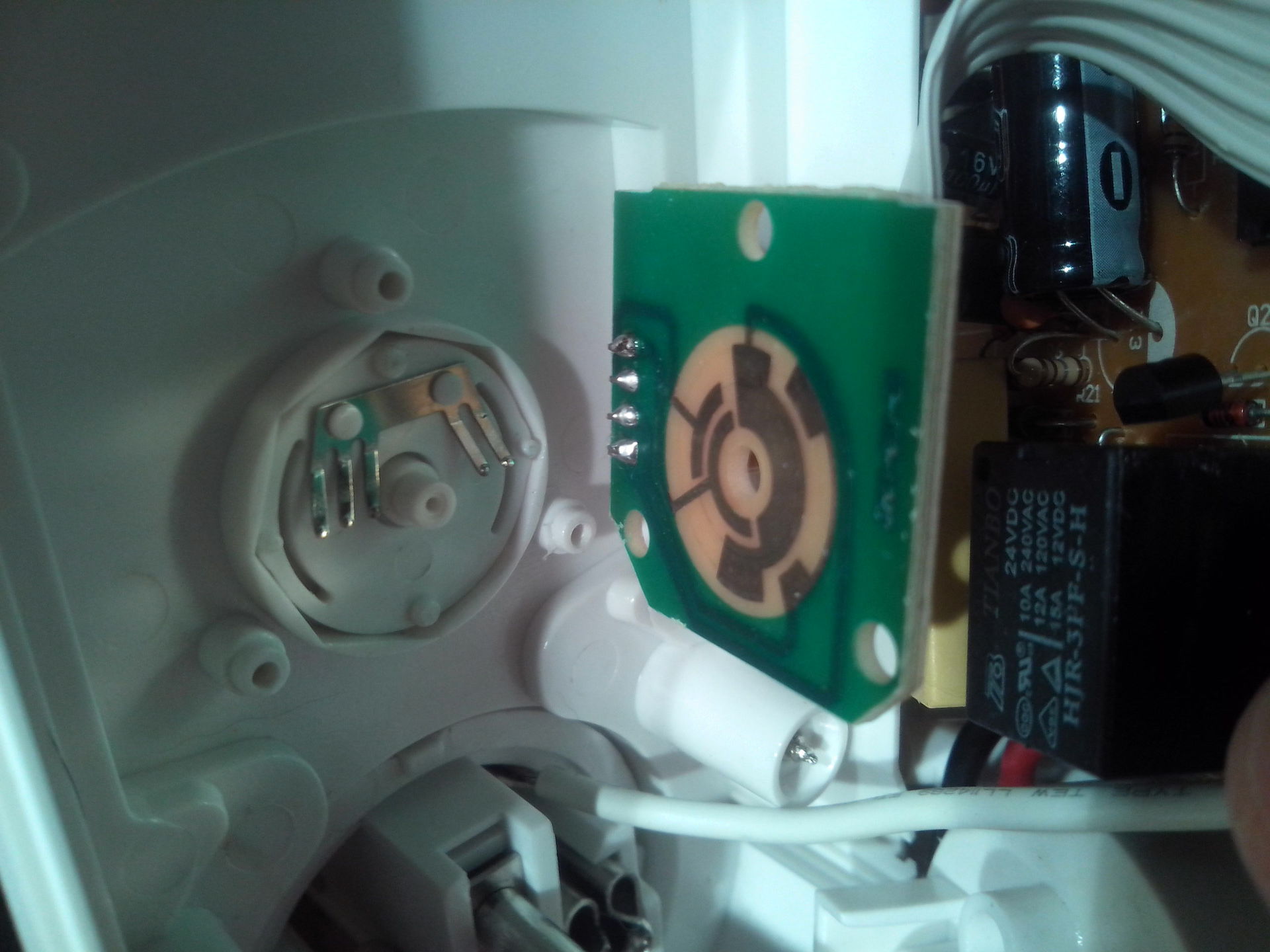
A quick look at the flux-stained board reveals the following picture:
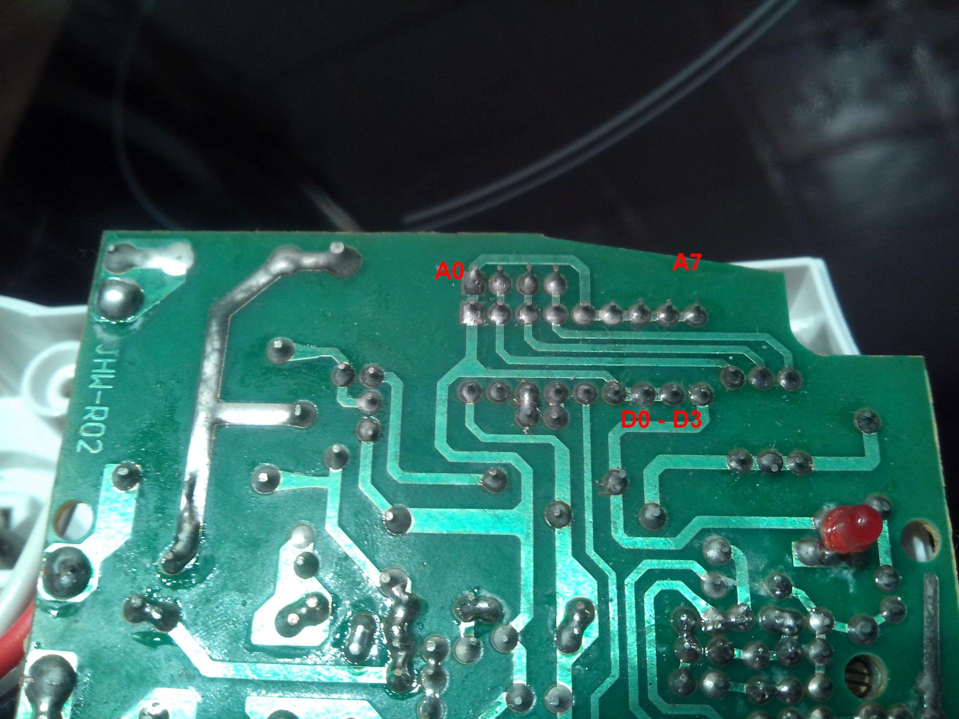
1) The address lines A0, A4 - A7 are immediately set on the ground (i.e., the corresponding bits are set to 0).
2) Address lines A1 - A3 on the one hand are pulled up to + 5V through resistors, and on the other, they are connected to the ground by an encoder (i.e., they take values from 000 to 111).
3) Data lines D1 - D3 are also connected to ground, and the control bit is left at the mercy of D0.
This is perhaps the most interesting. Of the less interesting - the type of relay, which shows that the kilowatt declared in the characteristics, it must withstand.
Guess the melody
Yeah, these bits! Want some street reverse engineering?
Of course, the sockets did not respond to the remotes I have - but it is good. Of course, blindly picking up at least one code did not work. Although no, I'm lying - in the process I accidentally came across one of the codes of the outlets already working for me. That's really lucky. In parallel, I reflected on why the author of RC-Switch speaks of a protocol with three bit states, although in the examples it uses only two: 0 and F.
This, as well as its claimed compatibility with the library, was somewhat confusing. Therefore, I decided to go the simple way, i.e. get rid of extra bits and conditions. The encoder logic clearly hinted that it has a position with three guaranteed zeros in the address bits, which are responsible for selecting the control channel. Add to this the rest of the address lines set on the ground - and get 8 zeros. It remains only to calculate the control bits of the data line.
It's funny, but the multimeter showed the three zeros if you set the encoder to the eighth channel. Those. the coding turned out "backwards":
8 - 000
7 - 100
6 - 010
5 - 110
4 - 001
3 - 101
2 - 011
1 - 111
And here, by the way, a third state was discovered that is not found in practical examples of RC-Switch. In other words, the address consists of 0 and 1, and just F is not used.
As for the data lines, judging by the pinout in the datasheets, the control bit with the same degree of probability could be D0 and D3. But in practice, this is still D0 (judging by the codeword scheme).
As a result of further experiments, it turned out that the on command is F000, and off is 0000 on the data line.
Here is a little code to demonstrate the process.
/*
http://dzrmo.wordpress.com/2012/07/08/remote-control-pt2272-for-android/
http://sui77.wordpress.com/2011/04/12/163/
http://code.google.com/p/rc-switch/
*/
#include
RCSwitch mySwitch = RCSwitch();
void setup() {
  // передатчик на цифровом пине 10
  mySwitch.enableTransmit(10);
}
// первый бит всегда 0
// следующие три бита, соответствующие номерам каналов (розеток)
// 8 - 000
// 7 - 100
// 6 - 010
// 5 - 110
// 4 - 001
// 3 - 101
// 2 - 011
// 1 - 111
// биты 5-8 - 0000
// последние четыре бита: F000 - ВКЛ
//                        0000 - ВЫКЛ
void loop() {
  // переключаем розетку #2 с интервалом в секунду
  mySwitch.sendTriState("00110000F000");
  delay(1000);
  mySwitch.sendTriState("001100000000");
  delay(1000);
}
Summary
What I wanted was what I got. The sockets are quite suitable for home use, the command system is solved by heroic efforts (again I guessed instead of gaining knowledge) and is easily implemented using the RC-Switch library in the code for Arduino. No remote needed.
Total - up to 8 extremely cost-effective remote control channels out of the box and the prospect of increasing them through the use of additional address lines (you just need to cut the tracks and pull them either to the plus or to the ground (the main thing is to prevent the address space from intersecting with equipment that is controlled by same data bits).
The obvious drawbacks are the unified address space and command system (from the same box) for all outlets. That is, if your neighbor buys the same, you will click on each other's outlets, unless, of course, someone guesses to correct the addresses.
In general, you can use.
ps. The described witchcraft for guessing may not work if a radically different chip is found, or its algorithm is implemented in a separate microcontroller (usually some PIC) without such obvious address and data lines. In these cases, you have to really put your head.









