How does the EIGRP protocol work?
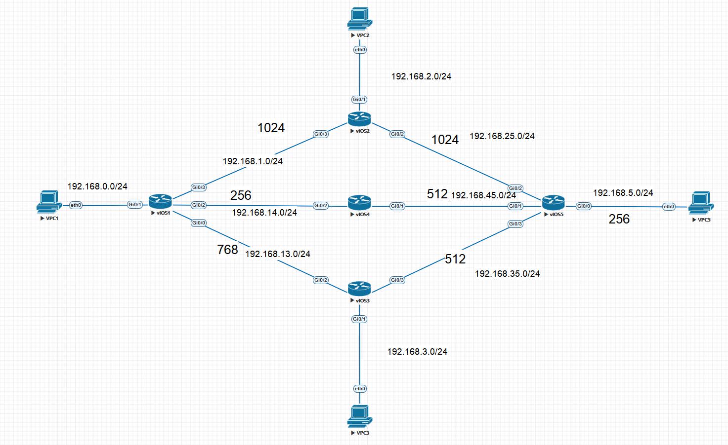
This article will talk about EIGRP and discuss how this protocol works. EIGRP is a distance vector protocol, sometimes talk about its hybridity, but it is not. Read the beginning of the article on OSPF and you will understand why EIGRP is a distance-vector protocol. EIGRP is an advanced distance vector dynamic routing protocol developed by Cisco. Let's start to understand. We will use the following topology:
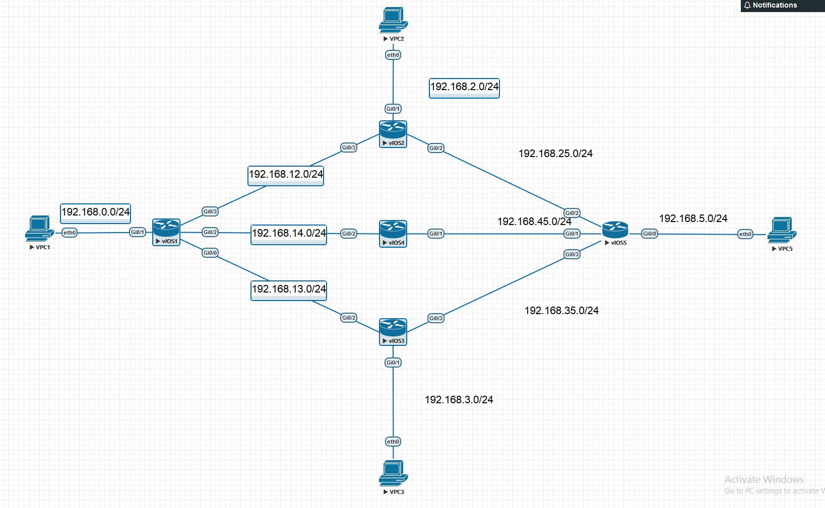
Let's run EIGRP on vIOS1 and on vIOS2, let's see how information is transmitted between routers. As soon as EIGRP is activated on the router, the router starts sending Hello packets. We also list other message types that are used in EIGRP.
There are also SIA packages, but we'll talk about them below.
Packets are sent to a multicast address of 224.0.0.10 every 5 seconds (Hello Timer), Hold Timer is 15 seconds = 3 hello intervals, if during this timer no hello packet was received from a neighbor, the neighbor is removed from the list of neighbors. The package looks like this:
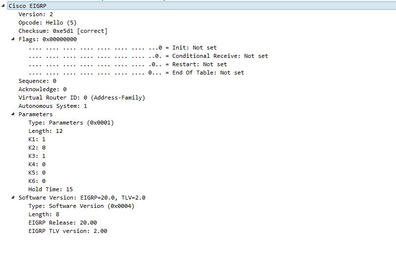
The package contains coefficients parameters (K1, K2, K3, K4, K5, K6), Hold Timer and Autonomous System number. The coefficients (K1, K2, K3, K4, K5, K6) are used in calculating the metrics and we will talk about them later, as well as the EIGRP timers. Now it is important to talk about the Autonomous System (AS). To activate EIGRP, a specific EIGRP process must be assigned a number, as in OSPF. But unlike OSPF, this parameter cannot be chosen randomly for each router; it must be the same for all routers. If the router receives a Hello packet with an AS different than it has, then the neighborhood relationship will not be.
In order for routers to become neighbors, the following conditions must be met:
In order for routers to become EIGRP neighbors, they do not have to match Hello and Hold time. The router uses the timer values received from the neighbor. If Hello or Hold timer is changed on one of the routers, then the neighbors of this router will use these values. In order for the router itself to use other values, it is necessary to change the timer on the corresponding neighbor interface. After the exchange of Hello packets, an Update packet is sent, but it does not yet contain routes, it contains the Init flag, which tells routers to start exchanging information about routes. This packet is sent directly to the address of the router. After exchanging such messages, each router sends an Update packet with routes to the multicast address 224.0.0.10:
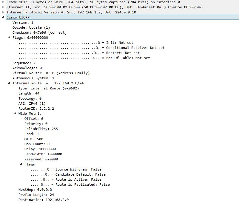
As you can see, the Update package does not contain any metric, but only information such as Bandwidth, Delay, MTU, etc. After receiving this information, the router itself calculates the metric based on K1-K6 coefficients. These packets can be sent either to a specific router or to a multicast link. In general, there are three types of updates:
Establishing a neighborhood at the packet level looks like this:

You can see that in addition to the Hello and Update that we have listed, there are also Hello (ACK) and the number is equal to the number of Update packets sent to the multicast address. It's all about the RTP protocol. RTP manages the EIGRP packet transfer process and provides:
That's it. What we have? Routes exchanged Update packets and now it's time to build a routing table. Each update is processed and substituting data (Bandwidth, Delay, etc.) into a special formula, the metric is calculated:
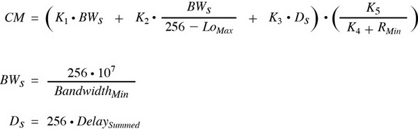
This is such a formula, it looks daunting, but the best thing about it is that you can not know it, just know that something like that exists. And another nice thing is that the default EIGRP coefficients are:
And the formula simply turns into metric = bandwidth + delay. Therefore, it is so important that the coefficients on all routers are the same, so that there are no problems due to different metrics on the routers. Let's talk about the data in Update in a little more detail.
As said above, by default they use bandwidth and delay. The remaining parameters are rarely needed, but with the help of them it is possible to fine-tune the metric. Thus, in the Update package, the router sends the route and its associated data, the metric itself does not transmit. The router that received Update calculates the metric by the formula and, depending on the metrics, decides whether to put the route in the routing table or not. It is also important to note that the router transmits only those routes that it uses itself. Let's see how to build a table topology.
Topology table- a list of routes learned from each neighbor. The topology table also stores the metric that each neighbor for each route (AD) reports and the metric that the local router will use to reach the route through the neighbor (FD).
It is necessary to clarify what AD and FD are. Configure EIGRP on all of our routers. Also, to avoid complex numbers in the metric, we change the coefficients from K1 = 1 K2 = 0 K3 = 1 K4 = 0 K5 = 0 to K1 = 0 K2 = 0 K3 = 1 K4 = 0 K5 = 0. Thus, we will have 256 * Delay formula and we also get an easy way to manipulate metrics by changing the delay parameter on the interfaces. Considering that delay = 1 sec on the interfaces, then each link, if using the OSPF terminology, costs 256. Let's see what the topology table on vIOS1 is:
If you look at the network, for example, 192.168.5.0/24, you can notice three ways through vIOS2, vIOS3 and vIOS4 with the same metrics. For 192.168.5.0/24 FD on all paths it is 768, and AD is 512. We give a definition from another article and try to explain:
We study this line from the topology table on vIOS1. vIOS1 learned about the route from vIOS4 (192.168.14.4). Since vIOS1 separates three links from 192.168.5.0/24, then the FD metric with our settings will be equal to 3 * 256 = 768. And AD is the route metric relative to the router (vIOS4) that announced this network. AD is the FD metric of this route on vIOS4. Let's look at the topology table on vIOS4:
AD on vIOS1 = FD on vIOS4. Silently confusing, but we will try to explain the logic of the work. The router, which announces the route, sends the parameters (Bandwithd, Delay, etc.) of the route in the Update message, without taking into account the link between the router that is being advertised. That is, vIOS4 takes into account only the parameters of two links: vIOS4 Gi0 / 1 - vIOS5 Gi0 / 1 and vIOS5 Gi0 / 0 - VPC. Having received Update, vIOS1, substituting the obtained parameters in the formula, calculates what? That's right - AD = 512. After it takes the parameters of the link where the route came from, vIOS1 Gi0 / 2 - vIOS4 Gi0 / 2 and substitutes it again in the formula. He counts, gets the number 256 and adds up with AD (512), we get FD - 768. These are the things! But why all this ritual?
And all in order to create a special rule called Feasible condition, which is one of the means of protection against the formation of loops and rapid convergence.
We give the definitions of the following terms:
To explain how it all works and show the subtleties, you need to change some of the metrics. Let's do the following, change the delay so that we have these link metrics:
This is done using the delay command on the interface. Now, as we said, delay = 1 and the metric is 256. Let's see what metrics we get for the 192.168.5.0/24 network on the vIOS1 router:
As we can see, the best FD will be at the route through vIOS4, it will be added to the general routing table, this route is called Successor :
What will happen to the other two routes - they will be checked for the condition FS (Feasible condition). The route through vIOS3 passes this condition AD (via vIOS3) = 768 <1024 = FD (via vIOS1). Therefore, this route, although it will not be added to the general routing table, will be stored in the topology tables:
It does not possess the metric of the best route, that is, it is not a Successor, but plays the role of a backup route and, if the Successor is lost, it will immediately take its place. This achieves a very fast protocol convergence, but more on that in more detail later. This route is called Feasible successor.. And what will happen to the third route? Nothing, it does not satisfy the condition FC (1280> 1024) and will not be taken into account in order to protect against the formation of a loop. All routes received via Update, but not passed the FC test, can be seen using the show ip eigrp topology all-links command. It’s not quite obvious why the FS condition protects against looping, now let's try to explain. It is important to know that when studying the EIGRP protocol, it is vital to understand the principle of the FC condition and the purpose for which it is used. Consider a slightly modified topology (a link between vIOS2 and vIOS4 is added), and also we use the most primitive metric:

The route to the network 192.168.5.0/24 will be like this with AD and FD:
But vIOS4 will receive an update from vIOS2, where the route to the network 192.168.5.0/24 via vIOS2 with the metric - AD = 12, FD = 15 will be contained. It is clear that it cannot be Successor, if suddenly this route were chosen by Feasible Successor, then if Successor fell on vIOS4 and then Successor chose this route, a loop would occur. But FC will not allow setting this route as FS as AD = 12> 10 = FD. The route on vIOS2 contains the path through vIOS4 and in any case FD vIOS4 also enters its AD. That is, AD on vIOS2 contains the following links:
Thus, the FC condition checks the route for the presence of itself in the given route. Only routes that satisfy this condition can guarantee that there are no loops. There may be cases when the route does not create a loop, but it does not satisfy the condition FC, we will not use it, in this case we choose the stability of the network. If you grasp, then the condition is quite simple and intuitive. The algorithm that selects the best routes in the EIGRP protocol is called DUAL. Now consider the EIGRP protocol to the question of convergence with the loss of the main route. Let's return to our old big topology and imagine that vIOS4 is missing. Depending on how vIOS4 disappeared, the behavior will be slightly different, but it will differ in how the trigger works. If, for example, we disable the Gi 0/2 interface on vIOS1, then vIOS1 immediately detects the loss of a neighbor and takes effect, if the neighbor disappears without warning, then the Hold Timer will work after it does not receive Hello packets within 15 seconds:
Led the routing table and topology again for convenience, so as to understand how the router will operate for each route, you need to know what condition they were in before. For example, the route 192.168.5.0/24, which we are discussing earlier, will be lost, but it has FS in the topology table and therefore, as soon as the loss of the main route is detected, it will take its place in the routing table. An interesting question is what will happen with routes without FS. But a little materiel:
Entries in the topology table can be in two states: active and passive. The route is in passive state when the route is stable and no search for the best route occurs. In the active state, if the search is for the best route. A route search is performed when there is no feasible successor for the destination network. The router in search of the best route sends a request (sends a query packet) to each neighboring router. If the neighbor has a route to the destination network, he answers (sends the reply packet); if there is no route, the neighbor sends a request to his neighbors. The router compares all FDs to reach a specific network, selects the route with the smallest FD, and places it in the routing table. The topology table can store 6 routes to the recipient's network (main and alternate).
The routes that were lost and did not have FS will be switched to the Active state and vIOS1 will start asking about them from the remaining neighbors. This is done using Query messages. vIOS1 will send Query messages to the routers vIOS2 and vIOS3, where it will explicitly indicate which routes it needs - in our case these routes will be 192.168.14.0/24, 192.168.45.0/24. With this message, vIOS1 also informs routers that routes through vIOS1 to these networks are unsuitable. This is done by specifying the Delay: Infifnity parameter in the metric of this route, that is, the metric is infinitely large. As soon as the routers receive such messages, they will delete these routes through vIOS1. This technology is called Poison Reverse.. Poison Reverse is also used in Update messages, and I'll talk about it a little later. After receiving the Query with a request for routes 192.168.14.0/24, 192.168.45.0/24, vIOS2 and vIOS3 will see if they have these routes that they use, if any, they will immediately send Reply with new metrics for these routes. vIOS2 and vIOS3 as we know, have not lost their routes, so they will immediately send Reply. If the router, which is asked also does not have this route, then it will forward the Query further to its neighbors, and so on. vIOS1 will wait for Reply from vIOS2, vIOS3 and then Active Timer comes on the scene, which will start as soon as the Query is sent:
Active Timer- time interval during which the route can remain in the active state. If the timer expires before all the responses from the neighbors (Reply) are received, the router switches the route to stuck-in-active. In addition, neighborhood relations are broken with those neighbors from whom no response was received. By default, this timer is 3 minutes.
That is, if Reply is not received within 3 minutes, despite Hello packets, the neighborhood will be broken and this is very bad. Despite the fact that 3 minutes seems like an eternity for such protocols, such situations are possible with large topologies. To protect against an erroneous break in the neighborhood relationship, special messages were invented - SIA-Query and SIA-Reply.
To improve the response of the router to the state of the active route, two types of messages are additionally introduced:
After 1.5 minutes, if Reply is not received on any Query, then SIA-Query is sent, which does not require a new route, but only needs to send SIA-Reply to make sure that the neighbor is ok, just cannot find the right one route.
I think about how the router reacts to the loss of the route when there is a FS or not, we said enough. Only need to make changes to the following. We did not give the correct definition for FD, the metric that we calculate according to the formula when we first receive the route or when we further change the state of the route, it would be correct to call CD - Computed Distance.
FD is the best indicator for a given route that has ever been obtained and that it participates in the verification of FC. Most often, FD = CD is the best route, but let's see how the FD has changed after breaking off the vIOS4 break:
We no longer have a route with CD = 1024, the best route through vIOS3 has CD = 1536, but as you can see, FD = 1024, which was fixed when there was a route through vIOS4. FD will be updated only when this route becomes Active. While the state did not change from Passive to Active, then FD will not change. Regular updates do not affect it. One more note. Let's do this experiment: let's return the neighborhood with vIOS4, CD via vIOS3 = 1536, and via vIOS2 = 2048. Increase the channel delay between vIOS1 and vIOS3 so that it becomes larger than the CD vIOS2:
As you can see the CD through vIOS3 = 2304, but it remained FS as AD did not change and the condition FC passed, as before. Let us ask ourselves the question: What will happen if the route is lost through vIOS2? The expected and logical answer, as we were taught, will be replaced by FS, but no! Since there is still a route through vIOS2, it has CD = 2048 <2304, the route will switch to Active and recalculate the metric for it and select the best route despite the fact that it had a backup route. We look at the topology table and get:
The route through vIOS2 will be used and as noted, FD also changed due to the transition of the route to the Active state. And the route through vIOS3 again shares the fate of the spare.
Like in RIP, EIGRP uses the Split Horizon rule - if a route is reachable through a specific interface, then the update that is sent through this interface does not include this route.
For example, having received the route vIOS4 to the network 192.168.0.0/24 from vIOS1, it will not send this route to Update via the interface to which vIOS1 is connected. To be more precise, let's imagine that vIOS1 started talking about the network 192.168.0.0/24. I sent Update to vIOS4, vIOS4 will receive it and as a rule Split Horizon should not send it Update with this route to vIOS1, but in reality it will send it with an indication of an infinite metric. How vIOS4 says vIOS1- “Do not dare use the route to the network 192.168.0.0/24 through me, I received this route from you and if you use it, there will be a loop”.
Poison Reverse - indication of a route unattainable with the help of a metric when it is lost. In EIGRP, this is done using the Delay parameter. We indicated above how this technology is used when the vIOS1 lost contact with the vIOS4. From what has been said above about Split Horizon, it can be concluded that the Poison Reverse technology is used not only in Query messages, but also in Update. Poison Reverse can also violate the Split Horizon rule and send Update with an infinite metric from the interface from which it received the update. These two rules, along with the FC condition, provide EIGRP protection against loops.
As an optimization of the work, the protocol introduced a special role for routers - Stub. Something like the Stub zone in OSPF, but here is a slightly different principle of operation. When you configure the router in stub mode, it immediately reports its stub status in Hello-packets to its neighbor and, depending on the stub mode, can send certain types of routes:
Options for the eigrp stub command:
But the main feature of this setting is that if the router knows that its neighbor is in the role of Stub, then it will not send Query for routes that have become Active. For example, if we configure vIOS5 as a Stub, then vIOS2-4 will find out about this and if routes are lost, they will not poison Query. Given what problems can arise in the absence of Reply, it would be good to send Query only where it makes sense. This is important in large topologies, where convergence can be a complex process. Therefore, if there is a router that is finite and only user networks are connected to it (relatively speaking, it has only one neighbor), then it is better to think about how to configure it as a Stub.
We talked about some of them, if we look at the output of the show ip eigrp neighbors command, we will see the following:
There are timers that require explanation. If, in response to sending any multicast packet that requires acknowledgment of receipt, an acknowledgment (ACK) was not sent, then a unicast packet will be sent to a neighbor who does not respond. If confirmation has not been received and after 16 unicast packets have been sent, then the neighbor is considered inactive.
On this I think to finish the article. The bottom useful links:
Let's run EIGRP on vIOS1 and on vIOS2, let's see how information is transmitted between routers. As soon as EIGRP is activated on the router, the router starts sending Hello packets. We also list other message types that are used in EIGRP.
- Hello - routers use hello packets to locate neighbors. Multicast packets are sent and do not require acknowledgment of receipt.
- Update - contains information about changing routes. They are sent only to routers affected by the update. These packets can be sent to a specific router (unicast) or group of routers (multicast). Receipt of an update package is confirmed by sending an ACK.
- Query - when the router does route counting and does not have a feasible successor, it sends a query packet to its neighbors in order to determine if they have a feasible successor for this destination. Typically, query packets are sent to multicast, but there may be unicast. Receipt of the query packet is confirmed by sending an ACK by the receiver of the packet.
- Reply — The router sends a reply packet in response to a query packet. Reply-packets are sent unicast to the one who sent the query-packet. Receipt of the reply packet is confirmed by sending an ACK.
- ACK is a packet that confirms receipt of update, query, reply packets. ACK packets are sent unicast and contain an acknowledgment number. In fact, these are hello packages that do not transmit data. Non-guaranteed delivery is used.
There are also SIA packages, but we'll talk about them below.
Packets are sent to a multicast address of 224.0.0.10 every 5 seconds (Hello Timer), Hold Timer is 15 seconds = 3 hello intervals, if during this timer no hello packet was received from a neighbor, the neighbor is removed from the list of neighbors. The package looks like this:
The package contains coefficients parameters (K1, K2, K3, K4, K5, K6), Hold Timer and Autonomous System number. The coefficients (K1, K2, K3, K4, K5, K6) are used in calculating the metrics and we will talk about them later, as well as the EIGRP timers. Now it is important to talk about the Autonomous System (AS). To activate EIGRP, a specific EIGRP process must be assigned a number, as in OSPF. But unlike OSPF, this parameter cannot be chosen randomly for each router; it must be the same for all routers. If the router receives a Hello packet with an AS different than it has, then the neighborhood relationship will not be.
In order for routers to become neighbors, the following conditions must be met:
- routers must authenticate,
- routers must be in the same AS,
- Neighborhood relations should be established on primary-addresses (when a hello-package arrives, the router checks whether the network sender's address belongs to the interface's primary-address),
- must match the values of K-coefficients.
In order for routers to become EIGRP neighbors, they do not have to match Hello and Hold time. The router uses the timer values received from the neighbor. If Hello or Hold timer is changed on one of the routers, then the neighbors of this router will use these values. In order for the router itself to use other values, it is necessary to change the timer on the corresponding neighbor interface. After the exchange of Hello packets, an Update packet is sent, but it does not yet contain routes, it contains the Init flag, which tells routers to start exchanging information about routes. This packet is sent directly to the address of the router. After exchanging such messages, each router sends an Update packet with routes to the multicast address 224.0.0.10:
As you can see, the Update package does not contain any metric, but only information such as Bandwidth, Delay, MTU, etc. After receiving this information, the router itself calculates the metric based on K1-K6 coefficients. These packets can be sent either to a specific router or to a multicast link. In general, there are three types of updates:
- Non-periodic (Nonperiodic) - updates are not sent at regular intervals, but when the topology or metric changes;
- Partial (Partial) - in updates not all the information from the routing table is transmitted, but only changes;
- Restricted (Bounded) - Updates are sent only to participating routers.
Establishing a neighborhood at the packet level looks like this:
You can see that in addition to the Hello and Update that we have listed, there are also Hello (ACK) and the number is equal to the number of Update packets sent to the multicast address. It's all about the RTP protocol. RTP manages the EIGRP packet transfer process and provides:
- Guaranteed package delivery.
- Saving order packages.
That's it. What we have? Routes exchanged Update packets and now it's time to build a routing table. Each update is processed and substituting data (Bandwidth, Delay, etc.) into a special formula, the metric is calculated:
This is such a formula, it looks daunting, but the best thing about it is that you can not know it, just know that something like that exists. And another nice thing is that the default EIGRP coefficients are:
- K1 = 1
- K2 = 0
- K3 = 1
- K4 = 0
- K5 = 0
And the formula simply turns into metric = bandwidth + delay. Therefore, it is so important that the coefficients on all routers are the same, so that there are no problems due to different metrics on the routers. Let's talk about the data in Update in a little more detail.
- Bandwidth - selected and sent to Update the minimum value among the bandwidth of channels leading to the network.
- Delay - summarizes the Delay of all channels leading to this network.
- Reliability - the worst indicator of reliability all the way, based on keepalive
- Loading - the worst indicator of link loading all the way, based on the packet rate and the configured bandwidth on the interface
- MTU is the smallest MTU all the way. Despite the fact that it is used in Update, it does not participate in the calculation of the metric itself.
As said above, by default they use bandwidth and delay. The remaining parameters are rarely needed, but with the help of them it is possible to fine-tune the metric. Thus, in the Update package, the router sends the route and its associated data, the metric itself does not transmit. The router that received Update calculates the metric by the formula and, depending on the metrics, decides whether to put the route in the routing table or not. It is also important to note that the router transmits only those routes that it uses itself. Let's see how to build a table topology.
Topology table- a list of routes learned from each neighbor. The topology table also stores the metric that each neighbor for each route (AD) reports and the metric that the local router will use to reach the route through the neighbor (FD).
It is necessary to clarify what AD and FD are. Configure EIGRP on all of our routers. Also, to avoid complex numbers in the metric, we change the coefficients from K1 = 1 K2 = 0 K3 = 1 K4 = 0 K5 = 0 to K1 = 0 K2 = 0 K3 = 1 K4 = 0 K5 = 0. Thus, we will have 256 * Delay formula and we also get an easy way to manipulate metrics by changing the delay parameter on the interfaces. Considering that delay = 1 sec on the interfaces, then each link, if using the OSPF terminology, costs 256. Let's see what the topology table on vIOS1 is:
iOS1 # show ip eigrp topology
EIGRP-IPv4 Topology Table for AS (1) / ID (192.168.1.1)
Codes: P - Passive, A - Active, U - Update, Q - Query, R - Reply,
r - reply Status, s - sia Status
P 192.168.3.0/24, 1 successors, FD is 512
via 192.168.13.3 (512/256), GigabitEthernet0 / 0
P 192.168.2.0/24, 1 successors, FD is 512
via 192.168.12.2 (512 / 256), GigabitEthernet0 / 3
P 192.168.25.0/24, 1 successors, FD is 512
via 192.168.12.2 (512/256), GigabitEthernet0 / 3
P 192.168.35.0/24, 1 successors, FD is 512
via 192.168.13.3 ( 512/256), GigabitEthernet0 / 0
P 192.168.12.0/24, 1 successors, FD is 256
via Connected, GigabitEthernet0 / 3
P 192.168.45.0/24, 1 successors, FD is 512
via 192.168.14.4 (512/256), GigabitEthernet0 / 2
P 192.168.0.0/24, 1 successors, FD is 256
via Connected, GigabitEthernet0 / 1
P 192.168.13.0/24, 1 successors, FD is 256
via Connected, GigabitEthernet0 / 0
P 192.168.14.0/24, 1 successors, FD is 256
via Connected, Gigabit Ethernet 0/2
P 192.168.5.0/24, 3 successors, FD is 768
via 192.168.12.2 (768/512), GigabitEthernet0 / 3
via 192.168.13.3 (768/512), GigabitEthernet0 / 0
via 192.168.14.4 (768/512), GigabitEthernet0 / 2
If you look at the network, for example, 192.168.5.0/24, you can notice three ways through vIOS2, vIOS3 and vIOS4 with the same metrics. For 192.168.5.0/24 FD on all paths it is 768, and AD is 512. We give a definition from another article and try to explain:
- Advertised distance (AD) , also known as reported distance (RD) - the cost of the distance between the neighboring router that advertises the route and the destination network.
- Feasible distance (FD) - the cost of the distance from the local router to the destination = AD network, which advertises the neighboring router + the cost of the distance between the local router and the neighboring router.
P 192.168.5.0/24, 3 successors, FD is 768 via 192.168.14.4 (768/512), GigabitEthernet0 / 2
We study this line from the topology table on vIOS1. vIOS1 learned about the route from vIOS4 (192.168.14.4). Since vIOS1 separates three links from 192.168.5.0/24, then the FD metric with our settings will be equal to 3 * 256 = 768. And AD is the route metric relative to the router (vIOS4) that announced this network. AD is the FD metric of this route on vIOS4. Let's look at the topology table on vIOS4:
P 192.168.5.0/24, 1 successors, FD is 512 via 192.168.45.5 (512/256), GigabitEthernet0 / 1
AD on vIOS1 = FD on vIOS4. Silently confusing, but we will try to explain the logic of the work. The router, which announces the route, sends the parameters (Bandwithd, Delay, etc.) of the route in the Update message, without taking into account the link between the router that is being advertised. That is, vIOS4 takes into account only the parameters of two links: vIOS4 Gi0 / 1 - vIOS5 Gi0 / 1 and vIOS5 Gi0 / 0 - VPC. Having received Update, vIOS1, substituting the obtained parameters in the formula, calculates what? That's right - AD = 512. After it takes the parameters of the link where the route came from, vIOS1 Gi0 / 2 - vIOS4 Gi0 / 2 and substitutes it again in the formula. He counts, gets the number 256 and adds up with AD (512), we get FD - 768. These are the things! But why all this ritual?
And all in order to create a special rule called Feasible condition, which is one of the means of protection against the formation of loops and rapid convergence.
We give the definitions of the following terms:
- Successor is a neighboring router with a loop-free path and the lowest cost path to the destination network.
- Feasible successor — backup router with no loop path (AD feasible successor must be less than FD of the current successor route).
- Feasible condition - AD feasible successor must be less than the FD of the current successor route.
To explain how it all works and show the subtleties, you need to change some of the metrics. Let's do the following, change the delay so that we have these link metrics:
This is done using the delay command on the interface. Now, as we said, delay = 1 and the metric is 256. Let's see what metrics we get for the 192.168.5.0/24 network on the vIOS1 router:
- Through vIOS2 - FD = 2304, AD = 1280
- Through vIOS4 - FD = 1024, AD = 768
- Through vIOS3 - FD = 1536, AD = 768
As we can see, the best FD will be at the route through vIOS4, it will be added to the general routing table, this route is called Successor :
iOS1 # show ip route eigrp
Codes: L - local, C - connected, S - static, R - RIP, M - mobile, B - BGP
D - EIGRP, EX - EIGRP external, O - OSPF, IA - OSPF inter area
N1 - OSPF NSSA external type 1, N2 - OSPF NSSA external type 2
E1 - OSPF external type 1, E2 - OSPF external type 2
i - IS-IS, su - IS-IS summary, L1 - IS-IS level-1, L2 - IS-IS level-2
ia - IS-IS inter area, * - candidate default, U - per-user static route
o - ODR, P - periodic downloaded static route, H - NHRP, l - LISP
a - application route
+ - route replicated,% - next hop override, p - overrides PfR from
Gateway of last resort is not set
D 192.168.2.0/24 [90/512] via 192.168.12.2, 06:01:31, GigabitEthernet0 / 3
D 192.168.3.0/24 [90/1024] via 192.168.13.3, 06:01:28, GigabitEthernet0 / 0
D 192.168.5.0/24 [90/1024] via 192.168.14.4, 06:01:28, GigabitEthernet0 / 2
D 192.168.25.0/24 [90/1024] via 192.168.14.4, 06:01:28, GigabitEthernet0 / 2
D 192.168.35.0/24 [90/1024] via 192.168.14.4, 06:01:28, GigabitEthernet0 / 2
D 192.168.45.0/24 [90/768] via 192.168.14.4; 06:01:28; GigabitEthernet0 / 2
What will happen to the other two routes - they will be checked for the condition FS (Feasible condition). The route through vIOS3 passes this condition AD (via vIOS3) = 768 <1024 = FD (via vIOS1). Therefore, this route, although it will not be added to the general routing table, will be stored in the topology tables:
iOS1 # show ip eigrp topology
EIGRP-IPv4 Topology Table for AS (1) / ID (192.168.1.1)
Codes: P - Passive, A - Active, U - Update, Q - Query, R - Reply,
r - reply Status, s - sia Status
P 192.168.3.0/24, 1 successors, FD is 1024
via 192.168.13.3 (1024/256), GigabitEthernet0 / 0
P 192.168.2.0/24, 1 successors, FD is 1024
via 192.168.12.2 (1024 / 256), GigabitEthernet0 / 3
P 192.168.25.0/24, 1 successors, FD is 1024
via 192.168.14.4 (1024/768), GigabitEthernet0 / 2
via 192.168.13.3 (1536/768), GigabitEthernet0 / 0
P 192.168.35.0/ 24, 1 successors, FD is 1024
via 192.168.14.4 (1024/768), GigabitEthernet0 / 2
via 192.168.13.3 (1280/512), GigabitEthernet0 / 0
P 192.168.12.0/24, 1 successors, FD is 768
via Connected, Gigabit Ethernet0 / 3
P 192.168.45.0/24, 1 successors, FD is 768
via 192.168.14.4 (768/512), GigabitEthernet0 / 2
P 192.168.0.0/ 24, 1 successors, FD is 512
via Connected, GigabitEthernet0 / 1
P 192.168.13.0/24, 1 successors, FD is 768
via Connected, GigabitEthernet0 / 0
P 192.168.14.0/24, 1 successors, FD is 256
via Connected, GigabitEthernet0 / 2
P 192.168.5.0/24, 1 successors, FD is 1024
via 192.168.14.4 (1024/768), GigabitEthernet0 / 2
via 192.168.13.3 (1536/768), GigabitEthernet0 / 0
It does not possess the metric of the best route, that is, it is not a Successor, but plays the role of a backup route and, if the Successor is lost, it will immediately take its place. This achieves a very fast protocol convergence, but more on that in more detail later. This route is called Feasible successor.. And what will happen to the third route? Nothing, it does not satisfy the condition FC (1280> 1024) and will not be taken into account in order to protect against the formation of a loop. All routes received via Update, but not passed the FC test, can be seen using the show ip eigrp topology all-links command. It’s not quite obvious why the FS condition protects against looping, now let's try to explain. It is important to know that when studying the EIGRP protocol, it is vital to understand the principle of the FC condition and the purpose for which it is used. Consider a slightly modified topology (a link between vIOS2 and vIOS4 is added), and also we use the most primitive metric:
The route to the network 192.168.5.0/24 will be like this with AD and FD:
- vIOS4 - via vIOS5, AD = 5, FD = 10.
- vIOS1 - via vIOS4, AD = 10, FD = 11.
- vIOS3 - via vIOS1, AD = 11, FD = 12.
But vIOS4 will receive an update from vIOS2, where the route to the network 192.168.5.0/24 via vIOS2 with the metric - AD = 12, FD = 15 will be contained. It is clear that it cannot be Successor, if suddenly this route were chosen by Feasible Successor, then if Successor fell on vIOS4 and then Successor chose this route, a loop would occur. But FC will not allow setting this route as FS as AD = 12> 10 = FD. The route on vIOS2 contains the path through vIOS4 and in any case FD vIOS4 also enters its AD. That is, AD on vIOS2 contains the following links:
12 = AD on vIOS2 = Gi0 / 3 vIOS3 + Gi0 / 2 vIOS4 + Gi0 / 1 vIOS5 + eth0 VPC5, where Gi0 / 1 vIOS5 + eth0 VPC5 = FD = 10 - this is FD vIOS4 and it is impossible that AD <FD was less.
Thus, the FC condition checks the route for the presence of itself in the given route. Only routes that satisfy this condition can guarantee that there are no loops. There may be cases when the route does not create a loop, but it does not satisfy the condition FC, we will not use it, in this case we choose the stability of the network. If you grasp, then the condition is quite simple and intuitive. The algorithm that selects the best routes in the EIGRP protocol is called DUAL. Now consider the EIGRP protocol to the question of convergence with the loss of the main route. Let's return to our old big topology and imagine that vIOS4 is missing. Depending on how vIOS4 disappeared, the behavior will be slightly different, but it will differ in how the trigger works. If, for example, we disable the Gi 0/2 interface on vIOS1, then vIOS1 immediately detects the loss of a neighbor and takes effect, if the neighbor disappears without warning, then the Hold Timer will work after it does not receive Hello packets within 15 seconds:
D 192.168.2.0/24 [90/512] via 192.168.12.2, 06:01:31, GigabitEthernet0 / 3
D 192.168.3.0/24 [90/1024] via 192.168.13.3, 06:01:28, GigabitEthernet0 / 0
D 192.168.5.0/24 [90/1024] via 192.168.14.4, 06:01:28, GigabitEthernet0 / 2
D 192.168.25.0/24 [90/1024] via 192.168.14.4, 06:01:28, GigabitEthernet0 / 2
D 192.168.35.0/24 [90/1024] via 192.168.14.4, 06:01:28, GigabitEthernet0 / 2
D 192.168.45.0/24 [90/768] via 192.168.14.4, 06:01:28, GigabitEthernet0 / 2
P 192.168.3.0/24, 1 successors, FD is 1024
via 192.168.13.3 (1024/256), GigabitEthernet0 / 0
P 192.168.2.0/24, 1 successors, FD is 1024
via 192.168.12.2 (1024/256), GigabitEthernet0 / 3
P 192.168.25.0/24, 1 successors, FD is 1024
via 192.168.14.4 (1024/768), GigabitEthernet0 / 2
via 192.168.13.3 (1536/768), GigabitEthernet0 / 0
P 192.168.35.0/24, 1 successors, FD is 1024
via 192.168.14.4 (1024/768), GigabitEthernet0 / 2
via 192.168.13.3 (1280/512), GigabitEthernet0 / 0
P 192.168.12.0/24, 1 successors, FD is 768
via Connected, GigabitEthernet0 / 3
P 192.168.45.0/24, 1 successors, FD is 768
via 192.168. 14.4 (768/512), GigabitEthernet0 / 2
P 192.168.0.0/24, 1 successors, FD is 512
via Connected, GigabitEthernet0 / 1
P 192.168.13.0/24, 1 successors, FD is 768
via Connected, GigabitEthernet0 / 0
P 192.168 .14.0 / 24, 1 successors, FD is 256
via Connected, GigabitEthernet0 / 2
P 192.168.5.0/24, 1 successors, FD is 1024
via 192.168.14.4 (1024/768), GigabitEthernet0 / 2
via 192.168.13.3 (1536/768), GigabitEthernet0 / 0
Led the routing table and topology again for convenience, so as to understand how the router will operate for each route, you need to know what condition they were in before. For example, the route 192.168.5.0/24, which we are discussing earlier, will be lost, but it has FS in the topology table and therefore, as soon as the loss of the main route is detected, it will take its place in the routing table. An interesting question is what will happen with routes without FS. But a little materiel:
Entries in the topology table can be in two states: active and passive. The route is in passive state when the route is stable and no search for the best route occurs. In the active state, if the search is for the best route. A route search is performed when there is no feasible successor for the destination network. The router in search of the best route sends a request (sends a query packet) to each neighboring router. If the neighbor has a route to the destination network, he answers (sends the reply packet); if there is no route, the neighbor sends a request to his neighbors. The router compares all FDs to reach a specific network, selects the route with the smallest FD, and places it in the routing table. The topology table can store 6 routes to the recipient's network (main and alternate).
The routes that were lost and did not have FS will be switched to the Active state and vIOS1 will start asking about them from the remaining neighbors. This is done using Query messages. vIOS1 will send Query messages to the routers vIOS2 and vIOS3, where it will explicitly indicate which routes it needs - in our case these routes will be 192.168.14.0/24, 192.168.45.0/24. With this message, vIOS1 also informs routers that routes through vIOS1 to these networks are unsuitable. This is done by specifying the Delay: Infifnity parameter in the metric of this route, that is, the metric is infinitely large. As soon as the routers receive such messages, they will delete these routes through vIOS1. This technology is called Poison Reverse.. Poison Reverse is also used in Update messages, and I'll talk about it a little later. After receiving the Query with a request for routes 192.168.14.0/24, 192.168.45.0/24, vIOS2 and vIOS3 will see if they have these routes that they use, if any, they will immediately send Reply with new metrics for these routes. vIOS2 and vIOS3 as we know, have not lost their routes, so they will immediately send Reply. If the router, which is asked also does not have this route, then it will forward the Query further to its neighbors, and so on. vIOS1 will wait for Reply from vIOS2, vIOS3 and then Active Timer comes on the scene, which will start as soon as the Query is sent:
Active Timer- time interval during which the route can remain in the active state. If the timer expires before all the responses from the neighbors (Reply) are received, the router switches the route to stuck-in-active. In addition, neighborhood relations are broken with those neighbors from whom no response was received. By default, this timer is 3 minutes.
That is, if Reply is not received within 3 minutes, despite Hello packets, the neighborhood will be broken and this is very bad. Despite the fact that 3 minutes seems like an eternity for such protocols, such situations are possible with large topologies. To protect against an erroneous break in the neighborhood relationship, special messages were invented - SIA-Query and SIA-Reply.
To improve the response of the router to the state of the active route, two types of messages are additionally introduced:
- SIA-Query - Dispatched after 1.5 minutes (default) in order to check the status of the directly attached router. In order that, if the route that is located behind a neighbor is missing (while communication with a neighbor is normal), the neighborhood relationship with the directly connected router is not reset. Does not require confirmation of receipt. After sending three messages and not receiving a response, the neighbor is considered to be in the down state and the route is removed from the topology table.
- SIA-Reply - Dispatched in response to SIA-Query. Does not require confirmation of receipt.
After 1.5 minutes, if Reply is not received on any Query, then SIA-Query is sent, which does not require a new route, but only needs to send SIA-Reply to make sure that the neighbor is ok, just cannot find the right one route.
I think about how the router reacts to the loss of the route when there is a FS or not, we said enough. Only need to make changes to the following. We did not give the correct definition for FD, the metric that we calculate according to the formula when we first receive the route or when we further change the state of the route, it would be correct to call CD - Computed Distance.
FD is the best indicator for a given route that has ever been obtained and that it participates in the verification of FC. Most often, FD = CD is the best route, but let's see how the FD has changed after breaking off the vIOS4 break:
P 192.168.5.0/24, 1 successors, FD is 1024
via 192.168.13.3 ( 1536 /768), GigabitEthernet0 / 0
We no longer have a route with CD = 1024, the best route through vIOS3 has CD = 1536, but as you can see, FD = 1024, which was fixed when there was a route through vIOS4. FD will be updated only when this route becomes Active. While the state did not change from Passive to Active, then FD will not change. Regular updates do not affect it. One more note. Let's do this experiment: let's return the neighborhood with vIOS4, CD via vIOS3 = 1536, and via vIOS2 = 2048. Increase the channel delay between vIOS1 and vIOS3 so that it becomes larger than the CD vIOS2:
P 192.168.5.0/24, 1 successors, FD is 1024
via 192.168.14.4 (1024/768), GigabitEthernet0 / 2
via 192.168.13.3 ( 2304 /768), GigabitEthernet0 / 0
As you can see the CD through vIOS3 = 2304, but it remained FS as AD did not change and the condition FC passed, as before. Let us ask ourselves the question: What will happen if the route is lost through vIOS2? The expected and logical answer, as we were taught, will be replaced by FS, but no! Since there is still a route through vIOS2, it has CD = 2048 <2304, the route will switch to Active and recalculate the metric for it and select the best route despite the fact that it had a backup route. We look at the topology table and get:
P 192.168.5.0/24, 1 successors, FD is 2048
via 192.168.12.2 (2048/1280), GigabitEthernet0 / 3
via 192.168.13.3 (2304/768), GigabitEthernet0 / 0
The route through vIOS2 will be used and as noted, FD also changed due to the transition of the route to the Active state. And the route through vIOS3 again shares the fate of the spare.
Split Horizon and Poison Reverse Rules in EIGRP
Like in RIP, EIGRP uses the Split Horizon rule - if a route is reachable through a specific interface, then the update that is sent through this interface does not include this route.
For example, having received the route vIOS4 to the network 192.168.0.0/24 from vIOS1, it will not send this route to Update via the interface to which vIOS1 is connected. To be more precise, let's imagine that vIOS1 started talking about the network 192.168.0.0/24. I sent Update to vIOS4, vIOS4 will receive it and as a rule Split Horizon should not send it Update with this route to vIOS1, but in reality it will send it with an indication of an infinite metric. How vIOS4 says vIOS1- “Do not dare use the route to the network 192.168.0.0/24 through me, I received this route from you and if you use it, there will be a loop”.
Poison Reverse - indication of a route unattainable with the help of a metric when it is lost. In EIGRP, this is done using the Delay parameter. We indicated above how this technology is used when the vIOS1 lost contact with the vIOS4. From what has been said above about Split Horizon, it can be concluded that the Poison Reverse technology is used not only in Query messages, but also in Update. Poison Reverse can also violate the Split Horizon rule and send Update with an infinite metric from the interface from which it received the update. These two rules, along with the FC condition, provide EIGRP protection against loops.
Stub routers
As an optimization of the work, the protocol introduced a special role for routers - Stub. Something like the Stub zone in OSPF, but here is a slightly different principle of operation. When you configure the router in stub mode, it immediately reports its stub status in Hello-packets to its neighbor and, depending on the stub mode, can send certain types of routes:
vIOS5 # eigrp stub [connected | leak-map | receive-only | redistributed | static | summary]
Options for the eigrp stub command:
- No options (default) - connected and summary;
- connected — Enables the stub router to send connected routes, but only for interfaces whose addresses are on the networks specified by the network command;
- leak-map - Allow dynamic prefixes based on the leak-map;
- receive-only - Prohibits the stub router from sending any routes;
- redistributed — Allows the stub router to send redistributed routes;
- static — Allows the stub router to send static routes, though the redistribution of static routes is already configured;
- summary — Allows the stub router to send summary routes (automatically added or administratively).
But the main feature of this setting is that if the router knows that its neighbor is in the role of Stub, then it will not send Query for routes that have become Active. For example, if we configure vIOS5 as a Stub, then vIOS2-4 will find out about this and if routes are lost, they will not poison Query. Given what problems can arise in the absence of Reply, it would be good to send Query only where it makes sense. This is important in large topologies, where convergence can be a complex process. Therefore, if there is a router that is finite and only user networks are connected to it (relatively speaking, it has only one neighbor), then it is better to think about how to configure it as a Stub.
A few words about timers
We talked about some of them, if we look at the output of the show ip eigrp neighbors command, we will see the following:
vIOS1 # show ip eigrp neighbors
EIGRP-IPv4 Neighbors for AS (1)
H Address Interface Hold Uptime SRTT RTO Q Seq
(sec) (ms) Cnt Num
2 192.168.14.4 Gi0 / 2 11 00:48:43 23 138 0 168
0 192.168.12.2 Gi0 / 3 12 02:31:12 6 100 0 258
1 192.168.13.3 Gi0 / 0 10 2d13h 7 100 0 291
vIOS1 #
There are timers that require explanation. If, in response to sending any multicast packet that requires acknowledgment of receipt, an acknowledgment (ACK) was not sent, then a unicast packet will be sent to a neighbor who does not respond. If confirmation has not been received and after 16 unicast packets have been sent, then the neighbor is considered inactive.
- Smooth round-trip time (SRTT) - the time between sending a packet to a neighbor and receiving confirmation from it. Measured in milliseconds. The calculation formula is proprietary.
- Multicast Flow Timer - the maximum interval in seconds during which the router will wait for an ACK packet after sending an EIGRP packet to a multicast address, before switching to unicast sending. Calculated from the SRTT, the calculation formula itself is proprietary.
- Retransmission timeout (RTO) - the interval between sending unicast-packets. Calculated from the SRTT, the calculation formula itself is proprietary.
On this I think to finish the article. The bottom useful links:
- cisconinja.wordpress.com/2009/09/18/eigrp-sia-query-and-sia-reply
- xgu.ru/wiki/EIGRP
- www.youtube.com/watch?v=FYUK7blhCZk - EIGRP webinar for about 4 and a half hours. Required to view)
- www.cisco.com/c/en/us/support/docs/ip/enhanced-interior-gateway-routing-protocol-eigrp/16406-eigrp-toc.html#anc9