Import coordinates from a text file into a nanoCAD drawing on the classic .NET API
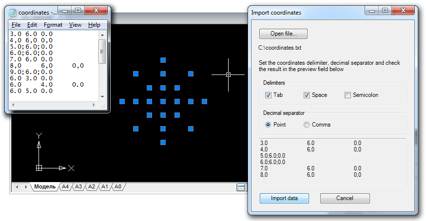
One of the most popular nanoCAD programming questions is “How do I import points from a text file?”. This task is not difficult, but a professional designer does not have to be a professional programmer, so we wrote this article in the style of "for beginners".
You can import coordinates into a drawing using any of the API types existing in nanoCAD. We decided to choose .NET and compare two close APIs: the classic .NET API and the cross-CAD platform MultiCAD.NET API. Under the cut - the first part - import of points on the classic .NET API.
Given: text file with coordinates of X, Y, Z points, one point on a line. The coordinates are separated by a space, the separator of the fractional part is a dot.
Required: write an application that, at the IMPORTCOORDS command, requests a file name and imports the coordinates found in the current drawing space as objects
DatabaseServices.DBPoint. Object coordinates must be imported in the current user coordinate system (UCS) of the drawing.Creating and setting up a working draft
To create the application, we need the following tools:
- nanoCAD (version not lower than 3.5)
- Microsoft Visual Studio 2008 (nanoCAD 3.5 - nanoCAD 5.0 supports loading of .NET applications built on the .NET Framework 3.5).
Well, of course, it is understood that you are at least a little able to program in C #. If not, welcome to the MSDN library .
Create a new project in Visual Studio with the following settings:
- Project type: Visual C #
- Template: Class Library
Thus, our application is a regular .NET assembly (DLL), which will subsequently be loaded into nanoCAD.
In the References tab, connect the following libraries that are part of the nanoCAD kit:
- hostdbmgd.dll
- hostmgd.dll
Now you can safely proceed to writing the program itself.
Program structure
The implementation can be broken down into the following steps:
- Register the IMPORTCOORDS command.
- Get the database of the current drawing and the command line editor.
- Request a file name with coordinates.
- Open file, read lines with coordinates.
- Create DBPoint objects with separate coordinates. Convert their coordinates to the current user coordinate system.
- Add created objects to the current drawing space (Model Space or Paper Space).
In order to register a command that will call our application in nanoCAD, before defining the method that will be called by this command, declare an attribute
[CommandMethod]and indicate the name of the command. Note that the method must have a public modifier:[CommandMethod("IMPORTCOORDS")]
publicvoidimportCoords()
{
...
}
Before continuing, I would like to stop and briefly tell what the “drawing database” is. The .dwg file is a database with a strict structure, the main elements of which are tables (Symbol Tables), which contain all the objects in the drawing. These are not only graphic objects that we see in the drawing (lines, arcs, points, etc.), but also many other objects that determine the contents and settings of the drawing. For example, the Layer Table contains all the layers that are on the drawing, the Linetype Table stores all line styles defined in the drawing, the UCS Table — all coordinate systems created by the user for a given drawing, etc. Thus, to create a new drawing object means to create the corresponding database object.
So continue. First of all, we need to select the current from all open documents and open its database. To do this, we get an object manager of all open documents, and then with its help a database with which we will continue to work.
DocumentCollection dm = Application.DocumentManager;
Database db = dm.MdiActiveDocument.Database;
In order for our application to request a file name, you need to get the Editor object and call the method that requests user input of a certain type (in our case, the file name):
// Получаем редактор командной строки
Editor ed = dm.MdiActiveDocument.Editor;
// Объект для получения результата запроса
PromptFileNameResult sourceFileName;
// Выводим запрос в командную строку и получаем результат
sourceFileName = ed.GetFileNameForOpen("\nEnter the name of the coordinates file to be imported:");
if (sourceFileName.Status == PromptStatus.OK)
{
  ...
}
Getting coordinates from a file is quite simple using the C # -functionality for reading text files and working with string data types:
// Читаем файл, получаем содержимое в виде массива строкstring[] lines = File.ReadAllLines(sourceFileName.StringResult);
// Для каждой строки записываем массив из подстрок, разделенных пробелом (т.к по условию задачи в качестве разделителя координат выступает символ пробела).// Таким образом получаем массив из координат, только в текстовом виде, затем конвертируем их в числа типа double.string[] coord;
foreach (string s in lines)
{
  coord = s.Split(newchar[] { ' ' });
  double coordX = Convert.ToDouble(coord[0]);
  double coordY = Convert.ToDouble(coord[1]);
  double coordZ = Convert.ToDouble(coord[2]);
}
We pass to creation of graphic primitives (Entity). As already noted above, in order to create any object (not only graphic) that will be stored in the drawing, it must be added to the drawing database, namely to the corresponding container object. So, for example, all layers are stored as records in the Layer Table, which in this case is a container object for them. The general structure of the database is as follows:

Graphic primitives are not stored directly in the database, but in the structure of individual blocks, which in turn are entries in the Block Table. This is very convenient, since such a mechanism makes it easy to group objects into named blocks and manage them as a whole. By the way, the model space and sheet space in the database are also represented by separate blocks. Thus, for a graphic primitive, the container will be a separate block, which, in turn, will belong to the parent object - the block table.
Since we are working with a database, it is necessary to ensure its integrity and protection in the event that any error occurred during program execution. For this purpose, a transaction mechanism is used. Transactions combine a number of operations that are performed as a whole: if something went wrong, the transaction is canceled, and objects created as part of this transaction will not be added to the document. If all operations completed successfully, then the transaction is confirmed, and objects are added to the database.
Armed with this knowledge, we can safely add the “point” primitives to the current drawing space in the coordinates that we read from the file.
using (Transaction tr = db.TransactionManager.StartTransaction())
{
  // Можно обойтись без таблицы блоков и получить блок текущего пространство чертежа прямо из объекта, представляющего базу данных
  BlockTableRecord btr = (BlockTableRecord)tr.GetObject(db.CurrentSpaceId, OpenMode.ForWrite);
  string[] lines = File.ReadAllLines(sourceFileName.StringResult);
  string[] coord;
  foreach (string s in lines)
  {
    coord = s.Split(newchar[] { ' ' });
    double coordX = Convert.ToDouble(coord[0]);
    double coordY = Convert.ToDouble(coord[1]);
    double coordZ = Convert.ToDouble(coord[2]);
    DBPoint point = new DBPoint(new Point3d(coordX, coordY, coordZ));
	btr.AppendEntity(point);
    tr.AddNewlyCreatedDBObject(point, true);
  }
  btr.Dispose();
  tr.Commit();
}
The task is practically solved. It remains to fulfill one condition: primitive points must be created in the coordinates of the user coordinate system (UCS). It should be noted that the primitives are stored in the drawing database in the world coordinate system (WCS). Therefore, when creating primitives, you must perform the conversion: UCS-> WCS. This is done using the matrix of the user coordinate system:
Matrix3d ucsMatrix = ed.CurrentUserCoordinateSystem;
Add the conversion:
{
  ...
  point.TransformBy(ucsMatrix.Inverse());
  ...
}
So, the program is completely written. What next?
Download application to nanoCAD
The most pleasant part remained - to download the program in nanoCAD and enjoy the results of your work. As you remember, we created the working project as a class library, therefore, after successful compilation, an assembly with the name of your project will be built. We open nanoCAD, at the command line we write the NETLOAD command, select the built library from the list and load it. To start the program, simply enter the name of the IMPORTCOORDS command on the command line.
Import coordinates. Version 2.0
We will improve the first version of the application by adding several useful functions and user interface elements.
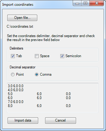
If the first version of the application “understood” a text file in which the coordinates were separated only by spaces and a dot was used as the decimal separator, now the application will be able to “recognize” the coordinates separated by a tab character, space or semicolon. As for the decimal separator, now it can be either a period or a comma; import will be performed without taking into account regional settings. The IMPORTCOORDS command will now open a modal dialog for importing coordinates, in which the user can select a file and specify the desired settings for importing coordinates.
The general mechanism for importing coordinates and creating primitives remains practically unchanged, but now it will happen within the form class, and the task of the IMPORTCOORDS command handler method now comes down only to creating a form object and displaying the form on the screen as a modal dialog:
[CommandMethod("IMPORTCOORDS")]
publicvoidimportCoords()
{
  Form form = new ImportForm();
  HostMgd.ApplicationServices.Application.ShowModalDialog(form);
}
After that, control will be transferred to the window of the coordinate import form.
Application form
The application form includes the following elements:
- Button for opening a file
- File open dialog
- A group of checkboxes for selecting coordinate separator characters: tab, space, semicolon
- Text box for previewing parsing lines with coordinates
- Button for importing coordinates
- Cancel button
Using these controls, the user can now specify the desired separator characters, check the result in the preview field (similar to how it was done in MS Excel when importing a text file) and initiate the import of coordinates:
AutoCAD compatible
In conclusion, I would like to note that an application written for nanoCAD can be easily recompiled to work in AutoCAD. To do this, do the following:
- In the References tab, connect the following libraries that are part of ObjectARX:
- AcCoreMgd.dll
- AcDbMgd.dll
- Acmgd.dll
- Add the conditional compilation directive to the application code to determine the namespaces that will be used for compilation under nanoCAD or AutoCAD:
#if ACADusing Autodesk.AutoCAD.ApplicationServices; using Autodesk.AutoCAD.DatabaseServices; using Autodesk.AutoCAD.EditorInput; using Autodesk.AutoCAD.Geometry; using Autodesk.AutoCAD.Runtime; using Platform = Autodesk.AutoCAD; using PlatformDb = Autodesk.AutoCAD; #elseusing HostMgd.ApplicationServices; using HostMgd.EditorInput; using Teigha.DatabaseServices; using Teigha.Geometry; using Teigha.Runtime; using Platform = HostMgd; using PlatformDb = Teigha; #endif - Replace the platform-specific namespaces with the aliases defined above:
PlatformandPlatformDb.
Both versions of the project are available here .
Discussion of the article is also available on our forum: forum.nanocad.ru/index.php?showtopic=6508 .
Translation of the article into English: Importing coordinates from a text file to a nanoCAD drawing using the classic .NET API .









