July 18, 2013 at 20:18
USB support in KolibriOS: what's inside? Part 4: Channel Support Level
- Tutorial
 The story about the level of interaction with host controllers stretched into two articles and still left some details behind the scenes - which, I hope, an interested reader can make up directly from the source . The level of support for channels is much simpler and is mainly occupied by converting API calls for higher levels into the desired sequence of actions, including blocking, with the necessary host controller.
Channel opening
The function
USBOpenPipefrom the API, called usb_open_pipein the pipe.inc code , opens a new channel according to the specified characteristics of the channel and the "parent" channel, where the characteristics of the device are recorded. To do this, she:- selects a pair of structures
*hci_pipe+usb_pipethat describe the channel and aligned to a controller-specific boundary by calling a controller-specific functionusb_hardware_func.AllocPipe; - selects a pair of structures
*hci_gtd+usb_gtdthat describe an empty transfer descriptor and aligned to a controller-specific boundary by calling a controller-specific functionusb_hardware_func.AllocTD; - fills in pointers: in the channel structure, copies a pointer to the controller structure and a pointer to device data common to all channels from the "parent" channel; between the channel structure and the structure of the empty descriptor fills the pointers round-trip; the structure of an empty descriptor makes it the only element of a doubly linked list of channels;
- initializes the mutex, which will guard all operations with this channel. Although all the processing of events from USB controllers takes place in a USB stream, the same cannot be said about accessing the API: an application reading a file from a USB flash drive initiates a transfer - and not even one - in the queue in the context of the application stream. So that the new transfer does not prevent the USB stream from processing the completion of the old transfer, this mutex is needed;
- Captures the mutex of the device’s channel set and makes sure that the device is not yet disconnected.
- invokes a controller-specific initialization
usb_hardware_func.InitPipeprotected by a mutex global for the controller; - Adds a new channel to the device channel set and releases the channel set mutex;
- if an error occurs at one of the steps, rolls back all the previous steps. Since it is most difficult to roll back the controller-specific initialization, it was done at the last stage, after which there can be no errors.
The controller-specific initialization by the last action adds a new channel to the corresponding list. For control channels, as well as for channels of data arrays, there is only one list, but for interrupt channels, you still need to choose one of several options.
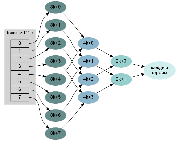
This is where scheduler.inc comes into play . He just chooses one of the lists of interrupt channels, and also makes sure that “there is enough space” for the new channel. I remind you that in every frame of the FullSpeed bus for periodic transmissions, you cannot use more than 90% of the time, and in every microframe of the HighSpeed bus - more than 80% of the time.
Here I should note that if for some reason you are writing a USB implementation that should workin your conditions, the planner can seriously save. You will have to in one way or another implement everything else that is described in this series of articles, but in the absence of a large load, you can manage with just one list of interrupt channels instead of a full tree, processed by each frame / microframe. A slightly more economical scheme, which does not complicate the implementation too much, is one list of channels for each processing interval of 1, 2, 4, 8, 16, 32 frames. While it is not necessary to simultaneously process more than one device with a lot of traffic per host controller, this approach is in no way inferior to a full-fledged scheduler. A simple circuit will “break” in some specific configurations with two or more isochronous channels of FullSpeed devices or three or more isochronous channels of HighSpeed devices, but maybe
If you are writing a USB implementation that should work everywhere and always , you also have to write a scheduler.
Transaction Time Estimation
Settlement data and internal transaction structure
One bit at FullSpeed speed is nominally transmitted per 1/12000 part of the frame, which gives a speed of 12 megabits / s. In other words, the “size” of one frame, as measured by the host controller, is 12,000 bits. Both the host and the device are ticking a timer that counts 1/12000 milliseconds; according to the timer, the host or device starts sending the next bit. The accuracy requirements for the host timer are quite stringent, and in the calculations, the host timer can be considered accurate. For external FullSpeed devices, the specification allows a timer error of ± 0.25%, which means that a 400-bit reception time from a device can correspond to a time from 399 to 401 “nominal FS-bits”. One bit at LowSpeed speed is nominally transmitted 8 times longer than at FullSpeed speed, which gives a speed of 1.5 megabits / s.
One bit at HighSpeed speed is nominally transmitted for 1/60000 part of the microframe, which gives a speed of 480 megabits / s. The accuracy requirements for the timer of HighSpeed devices have been increased to ± 0.05%, so that when planning transactions, the resulting error due to the difference in timers can be neglected.
Transactions have their own internal structure. Let us leave aside the split transactions. Normal transactions consist of several packagesfollowing the USB bus strictly sequentially without alternating with other packets: a packet with a token (Token), an optional packet with data (Data), an optional feedback packet (Handshake). Packets directed from the host to the LowSpeed device are preceded by a separate special PRE packet. The PRE packet and a pause after it with a minimum of 4 “nominal FS bits” are needed so that the hubs on the bus can unblock the ports to which LowSpeed devices are connected. Normal FullSpeed traffic is not transmitted to such ports.
Each packet starts with a SYNC clock of 8 bits = 1 byte at Low / Full-Speed and 32 bits = 4 bytes at HighSpeed. Each packet, except for the special PRE packet, ends with an EOP (end of packet) sequence of 3 bits at Low / Full-Speed and 8 bits at HighSpeed.
The token determines the action, direction of transmission, address and endpoint of the device receiving / transmitting data. In normal transactions, three tokens are possible: IN, OUT, and SETUP for receiving data, sending data, and the first stage of control transmission, respectively. A packet with a token takes 3 bytes, not counting SYNC + EOP: 8 bits for the type of packet, 7 bits of the device address, 4 bits of the endpoint and 5 bits of CRC, confirming the absence of errors when transmitting the address of the device and the endpoint.
The data packet contains the actual data sent or received from the device, as well as 3 additional bytes, not counting SYNC + EOP: 8 bits for the type of packet and 16 bits of CRC data.
The feedback packet consists of one byte, not counting SYNC + EOP: 8 bits for the packet type. The packet is sent in the opposite direction to the previous packet. An ACK packet means that all data has been successfully received. In IN transactions, a NAK packet is sent by the device instead of a data packet and means that there is no data yet. For example, the mouse will respond this way while the controller polls it regularly, but the state has not changed since the last poll. In OUT transactions, the NAK packet is sent by the device after the data packet and means that while the device is busy with internal affairs, so the host should try again later. NAK is not a mistake. To signal an error, the device may not respond at all, respond with an invalid packet, or respond with a STALL packet. In the first two cases, the controller will consider this an error somewhere on the bus and will retry up to three times, after which it will give up and report an error. In the latter case, the controller will report an error immediately.
In isochronous transactions, there is no feedback packet. In interrupt transactions, a feedback packet is required.
In data transmitted via USB, a zero bit is inserted after every six unit bits. The single bits are encoded so that the bus state does not change with a single bit, a timer is used to select individual bits. A zero bit is inserted so that the tolerance in the timers does not cause problems. Therefore, in the worst case, the package delivery time must be multiplied by 7/6. The multiplier does not apply to SYNC and EOP: they are encoded in a special way, generating guaranteed changes in the state of the bus.
If the host controller sends two packets in a row, only a short inter-packet delay is sufficient, corresponding to a 2-bit transmission in the case of FullSpeed and LowSpeed and 88 bits in the case of HighSpeed. If the controller has received a packet and must send a response packet, the pause is reduced to 8 bits in the case of HighSpeed and the same 2 bits in the case of FullSpeed and LowSpeed. If the host controller has sent a packet and is waiting for a response packet, then you need to consider the delay in passing the packet to the device and the response packet from the device (turn-around time). For FullSpeed and LowSpeed buses, the specification defines the maximum delay, including the signal passing in both directions and the response of the device, as a transmission time of 18 bits with the corresponding speed. For HighSpeed, the maximum delay is equivalent to a transmission time of 736 bits.
One bit at HighSpeed speed is nominally transmitted for 1/60000 part of the microframe, which gives a speed of 480 megabits / s. The accuracy requirements for the timer of HighSpeed devices have been increased to ± 0.05%, so that when planning transactions, the resulting error due to the difference in timers can be neglected.
Transactions have their own internal structure. Let us leave aside the split transactions. Normal transactions consist of several packagesfollowing the USB bus strictly sequentially without alternating with other packets: a packet with a token (Token), an optional packet with data (Data), an optional feedback packet (Handshake). Packets directed from the host to the LowSpeed device are preceded by a separate special PRE packet. The PRE packet and a pause after it with a minimum of 4 “nominal FS bits” are needed so that the hubs on the bus can unblock the ports to which LowSpeed devices are connected. Normal FullSpeed traffic is not transmitted to such ports.
Each packet starts with a SYNC clock of 8 bits = 1 byte at Low / Full-Speed and 32 bits = 4 bytes at HighSpeed. Each packet, except for the special PRE packet, ends with an EOP (end of packet) sequence of 3 bits at Low / Full-Speed and 8 bits at HighSpeed.
The token determines the action, direction of transmission, address and endpoint of the device receiving / transmitting data. In normal transactions, three tokens are possible: IN, OUT, and SETUP for receiving data, sending data, and the first stage of control transmission, respectively. A packet with a token takes 3 bytes, not counting SYNC + EOP: 8 bits for the type of packet, 7 bits of the device address, 4 bits of the endpoint and 5 bits of CRC, confirming the absence of errors when transmitting the address of the device and the endpoint.
The data packet contains the actual data sent or received from the device, as well as 3 additional bytes, not counting SYNC + EOP: 8 bits for the type of packet and 16 bits of CRC data.
The feedback packet consists of one byte, not counting SYNC + EOP: 8 bits for the packet type. The packet is sent in the opposite direction to the previous packet. An ACK packet means that all data has been successfully received. In IN transactions, a NAK packet is sent by the device instead of a data packet and means that there is no data yet. For example, the mouse will respond this way while the controller polls it regularly, but the state has not changed since the last poll. In OUT transactions, the NAK packet is sent by the device after the data packet and means that while the device is busy with internal affairs, so the host should try again later. NAK is not a mistake. To signal an error, the device may not respond at all, respond with an invalid packet, or respond with a STALL packet. In the first two cases, the controller will consider this an error somewhere on the bus and will retry up to three times, after which it will give up and report an error. In the latter case, the controller will report an error immediately.
In isochronous transactions, there is no feedback packet. In interrupt transactions, a feedback packet is required.
In data transmitted via USB, a zero bit is inserted after every six unit bits. The single bits are encoded so that the bus state does not change with a single bit, a timer is used to select individual bits. A zero bit is inserted so that the tolerance in the timers does not cause problems. Therefore, in the worst case, the package delivery time must be multiplied by 7/6. The multiplier does not apply to SYNC and EOP: they are encoded in a special way, generating guaranteed changes in the state of the bus.
If the host controller sends two packets in a row, only a short inter-packet delay is sufficient, corresponding to a 2-bit transmission in the case of FullSpeed and LowSpeed and 88 bits in the case of HighSpeed. If the controller has received a packet and must send a response packet, the pause is reduced to 8 bits in the case of HighSpeed and the same 2 bits in the case of FullSpeed and LowSpeed. If the host controller has sent a packet and is waiting for a response packet, then you need to consider the delay in passing the packet to the device and the response packet from the device (turn-around time). For FullSpeed and LowSpeed buses, the specification defines the maximum delay, including the signal passing in both directions and the response of the device, as a transmission time of 18 bits with the corresponding speed. For HighSpeed, the maximum delay is equivalent to a transmission time of 736 bits.
The host controller hides the implementation of all these details of the transaction, for planning it is enough to know how long the transaction will take. The time depends on the type of transaction, the direction of the transaction and the speed of the device.
- An interrupt read transaction consists of a packet with a token to the device, waiting for a response from the device, a packet with data from the device, a pause after a received packet, a packet with feedback to the device, a pause after a sent packet.
- HighSpeed bus: 68 bits in the first packet, 736 bits of waiting, 40+ (7/6) * 8 * (data size + 3) bits in the second packet, 8 bits of pause, 49 bits in the last packet, another 88 bits of pause - total 989 + 8 * (7/6) * (data size + 3) bits maximum.
- FullSpeed bus: 39 bits in the first packet, 18 bits of waiting, (401/400) * (11+ (7/6) * 8 * (data size + 3)) bits in the second packet, 2 bits of a pause, 20 bits in the last packet, another 2 bits of pause - a total of 93 + 2807/300 * (data size + 3) bits maximum.
- LowSpeed bus: 16 FS-bits of the preamble to the first packet and 4 FS-bits to the response of the hubs, 8 * 39 FS-bits in the first packet, 8 * 18 FS-bits of wait, (406/50) * (11+ (7 / 6) * 8 * (data size + 3)) FS-bits in the second packet, 8 * 2 FS-pause bits, 16 FS-bits of the preamble to the last packet and 4 FS-bits to the response of the hubs, 8 * 20 FS- bit in the last packet, another 8 * 2 pause bits - total 778 + 5684/75 * (data size + 3) FS-bit maximum.
- An interrupt write transaction consists of a packet with a token to the device, a pause after the sent packet, a packet with data to the device, waiting for a response from the device, a packet with feedback from the device, a pause after the received packet. The difference from reading, not counting the order of the terms, is only in the direction of transmission.
- HighSpeed-bus: the same 989 + 8 * (7/6) * (data size + 3) bits maximum.
- FullSpeed bus: the 401/400 multiplier "moves" from the data packet to the feedback packet, totaling 93 + 28/3 * (data size + 3) bits maximum.
- LowSpeed bus: multipliers 406/50 and 8 in two data and feedback packets are interchanged, total 778 + 224/3 * (data size + 3) FS-bit maximum.
- An isochronous read transaction consists of a packet with a token to the device, waiting for a response from the device, a packet with data from the device, a pause after the received packet
- HighSpeed bus: 68 bits in the first packet, 736 bits of waiting, 40+ (7/6) * 8 * (data size + 3) bits in the second packet, 8 bits of a pause - total 852 + 8 * (7/6) * (data size + 3) bits maximum.
- FullSpeed bus: 39 bits in the first packet, 18 bits of waiting, (401/400) * (11+ (7/6) * 8 * (data size + 3)) bits in the second packet, 2 bits of a pause - total 71 + 2807/300 * (data size + 3) bits maximum.
- On a LowSpeed bus, isochronous transactions are prohibited by the specification.
- An isochronous write transaction consists of a packet with a token to the device, a pause after the sent packet, a packet with data to the device, another pause after the sent packet.
- HighSpeed bus: 68 bits in the first packet, 88 bits of pause, 40+ (7/6) * 8 * (data size + 3) bits in the second packet, another 88 bits of pause - total 284 + 8 * (7/6) * (data size + 3) bits maximum.
- FullSpeed bus: 39 bits in the first packet, 2 pause bits, 11+ (7/6) * 8 * (data size + 3) bits in the second packet, another 2 pause bits - total 54 + 8 * (7/6) * (data size + 3) bits maximum.
- On a LowSpeed bus, isochronous transactions are prohibited by the specification.
- Split read interrupt transaction and isochronous read transaction. The Start-Split transaction consists of an SPLIT packet, a pause after a sent packet, a packet with a token, a pause after a sent packet - a total of 321 bits. The Complete-Split transaction consists of an SPLIT packet, a pause after a sent packet, a packet with a token, waiting for a response from the device, a data packet, a pause after a received packet - total 1017 + 8 * (7/6) * (data size + 3) bits .
- Split interrupt write transaction. The Start-Split transaction consists of an SPLIT packet, a pause after a sent packet, a packet with a token, a pause after a sent packet, a data packet, a pause after a sent packet - total 449 + 8 * (7/6) * (data size + 3) bits . The Complete-Split transaction consists of an SPLIT packet, a pause after a sent packet, a packet with a token, waiting for a device response, a feedback packet, a pause after a received packet - a total of 1026 bits.
- Split isochronous write transaction. The Start-Split transaction has the same structure as in the case of an interrupt write transaction, 449 + 8 * (7/6) * (data size + 3) bits. Transaction Complete-Split is missing.
Scheduler
On the FullSpeed / LowSpeed bus for one frame, there can be no more than one transaction on one channel, transfers from more than one transaction are divided into several frames. On the HighSpeed bus, the maximum number of transactions per microframe can reach 3 and is one of the characteristics of the channel along with the maximum transaction size.
When a channel is opened, the scheduler must reserve a portion of 90% of the frame / 80% of the microframe behind the channel, based on the worst case of using the channel - assuming the maximum possible number of the longest transactions. Transaction duration is described in the previous section. If you cannot reserve a part of the channel due to the fact that everything is already taken by other channels, the scheduler should return an error. When a driver detects an error, it may, for example, try to negotiate with the device to reduce traffic due to something or inform the user (through the control program) that it is impossible to work in such conditions.
Split transactions add complexity. Firstly, you need to reserve and keep records on two tires. Secondly, microframes appear on the FullSpeed / LowSpeed bus: if a Start-Split transaction from a host to TT arrives in microframe N, then TT will be able to start this transaction only in microframe N + 1, and return results in transaction Complete-Split not earlier microframe N + 2. Thirdly, although a maximum of 90% of the frame for all periodic transactions in the worst case remains, planning on the FS / LS bus should be based on an optimistic estimate without a 7/6 multiplier due to bit insertion, the USB2 specification in the face of section 11.18 “Periodic Split Transaction Pipelining and Buffer Management ”calls such an assessment“ best-case budget ”- this reduces the chances that the FS / LS bus will be idle due to the fact that one periodic transaction completed earlier than calculated, the next periodic transaction can start no earlier than the next microframe, because the Start-Split transaction data has not yet arrived for it, and there is not enough time for the next non-periodic transaction in the remainder of the current microframe. Finally, the host does not know when the transaction will be completed, and the TT buffers for storing the results are not rubber, so the Complete-Split transaction needs to be scheduled several times - one in each microframe following the microframe, in which the transaction can be completed. Specific requirements are outlined in the same section 11.18: as part of an interrupt transaction, budget starting in microframe N, one Start-Split transaction in microframe N-1 and three Complete-Split transactions in microframe N + 1, N + 2 must be scheduled , N + 3. Isochronous read transactions differ only in which can occupy several microframes N, ..., L in the budget, which is why Complete-Split transactions need to be planned in microframes from N + 1 to L + 3 inclusive. In isochronous transactions, Complete-Split transactions are not written, but there can be several Start-Split transactions: less than 188 bytes can fit in one microframe on the FS bus, and if there is more data, they will be divided into several Start-Split transactions with a limit of 188 bytes in one transaction.
The KolibriOS scheduler is trying to achieve the most even distribution of reserved parts in different frames / microframes, trying to ensure that in the phrase “there is X or more free time in each frame / microframe”, the number X would be as large as possible. If a channel appears later that requires attention to each frame / microframe, a large X value is necessary for a successful reservation. If it does not appear, time will come in handy for non-periodic transmissions.
First, the scheduler selects the real interval at which the host controller will poll the channel. This is the easy part of the task: to choose from the numbers 1, 2, 4, 8, 16, 32 the maximum, not more than the given. Next, you need to choose from all lists with an already selected interval. I will take USB1 and an interval of 8 frames as an example. Then there are 8 options: a list of channels processed in frames of the form 8k + 0, ..., a list of channels processed in frames of the form 8k + 7. Scheduling is repeated every 32 frames; option 8k + 0 in one planning range contains 4 frames 0,8,16,24, in each of which different sets of channels can be planned. To calculate the total time reserved for periodic transactions in a frame, for example, 24, you need to sum the data according to the lists of already opened channels corresponding to 32k + 24, 16k + 8, 8k + 0, 4k + 0, 2k + 0, to every frame. Having calculated such a time for each of the frames 0,8,16,24, the scheduler takes a maximum and associates it with the 8k + 0 option. Similarly, the maximum time reserved for existing channels is calculated for the remaining options 8k + 1, ..., 8k + 7. The best option is the one with the maximum reserved time less than the rest, and the free time, respectively, more than the rest. Having chosen the best option, the scheduler checks that time reservation for the new channel will not overflow 90% of the frame, and assigns the selected option to the new channel. in which the maximum reserved time is shorter than the rest, and the free time, respectively, is greater than the rest. Having chosen the best option, the scheduler checks that time reservation for the new channel will not overflow 90% of the frame, and assigns the selected option to the new channel. in which the maximum reserved time is shorter than the rest, and the free time, respectively, is greater than the rest. Having selected the best option, the scheduler checks that the reservation of time for the new channel will not overflow 90% of the frame, and assigns the selected option to the new channel.
Planning HighSpeed transactions in USB2 is similar to USB1 with two differences: there are 8 times more options due to microframes; if there are several options with the same time, then the scheduler selects the one that is closer to the end of the frame in order to minimize conflicts with split transactions.
Split transaction planning in USB2 follows the same principles, but the details are even more complicated. Options where it is impossible to reserve enough time on at least one of the tires are discarded even before comparison. As the main criterion for the quality of the variant, the budget on the FS bus is used as a more limited one. With an equal budget, the scheduler selects the option closest to the start of the frame. If there are still options, the last criterion is the time on the HS bus, the maximum of all Start-Split and Complete-Split transactions.
Explicit channel closure and device shutdown
The function
USBClosePipefrom the API, named usb_close_pipein the pipe.inc code, closes the specified channel. To do this, it captures the mutex of the device’s channel set, sets the “owner refused the channel” bit, calls the general channel closure function usb_close_pipe_nolock, releases the mutex of the device’s channel set and wakes up the USB stream to process the change in the channel lists. When the device is disconnected, the controller-specific code or the hub driver calls a function
usb_device_disconnectedthat captures the mutex of the device’s channel set, passes through all the channels, for each it calls the general function usb_close_pipe_nolock, after remembering which channel goes next, at the end it releases the mutex of the device’s channel set. There is no need to wake up the USB stream, because it does not sleep anyway, being busy with the execution of this code.General function
usb_close_pipe_nolock:- Captures the channel mutex (perhaps by waiting for the transfer to the queue to finish);
- checks that the channel is not yet closed, and sets the “channel is closed” bit (after which new transfers will not be added to the queue - the mutex is captured for this);
- releases the channel mutex;
- Deletes a channel from the device’s channel set
- calls the controller-specific function
usb_hardware_func.UnlinkPipeprotected by the mutex global for the controller, which will remove the channel from the corresponding list of channels and inform scheduler.inc about the removal of the channel.
The remote channel can still be processed by the controller for some time, so the final deletion occurs a bit later, when the controller-specific code calls a function
usb_pipe_closedthat:- it passes in turn the remaining transmissions, calls the callback-functions with the error "the channel has closed" and frees all the descriptors of the transmissions;
- if this is not the last channel of the device and the “driver abandoned device” bit is set, it simply frees the memory allocated for the channel structure;
- if this is not the last channel of the device and the “driver abandoned device” bit is cleared, then adds the channel to the list of device channels to be freed;
- if this is the last channel of the device, it calls the functions of
DeviceDisconnectedall device drivers, marks the address of the device on the bus, if it was assigned as free, frees the memory allocated for the channel structure, and also goes through the list of device channels to be freed, and frees the memory, allocated to them.
Array transfers and interrupt transfers
Such transfers consist of one stage, so the function
USBNormalTransferAsyncfrom the API, named usb_normal_transfer_asyncin the pipe.inc code, is simple: it captures the channel mutex, checks that the channel is not closed yet, creates a transfer by calling the controller-specific function usb_hardware_func.AllocTransfer, indicating to use the direction stored in the channel structure when opened, activates the call transfer usb_hardware_func.InsertTransferand releases the channel mutex.Control gears
Control transfers consist of two or three stages with data transferred in different directions, so the function
USBControlTransferAsyncfrom the API, named usb_control_asyncin the pipe.inc code, is somewhat more complicated USBNormalTransferAsync. 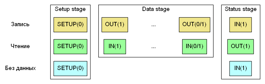
Here is a controller specific function
usb_hardware_func.AllocTransfercalled twice or thrice, according to the number of stages. The direction of transmission is set explicitly. In addition, another transmission characteristic is explicitly specified - the Toggle bit. Non-isochronous transactions in USB “are painted in two alternating colors” to track the situation when a packet does not reach the destination. For interrupt channels and channels of data arrays, the rotation is cross-cutting across all transfers: if the transfer ended on a transaction with Toggle = 0, the next transfer will start with Toggle = 1 and vice versa. In control transmissions, the Toggle bit is reset with each new step, as shown in the figure.All articles in the series
Part 1: general scheme
Part 2: basics of working with host controllers
Part 3: host controller support code
Part 4: channel support level
Part 5: logical device level
Part 6: hub driver