July 7, 2013 at 16:04
UEFI BIOS file device, part two: UEFI Firmware Volume and its contents
- Tutorial
Behind already one and a half ( first , one and a half ) parts of this article, now finally it's time to talk about the structure of the UEFI Firmware Volume and the UEFI File System format.
I must say right away that in this part of the article I will describe the file formats of version 2, because they are used in all existing BIOSes. In the latest versions of the PI standard , a description of the formats of version 3 has been added, but they are needed for files larger than 16 MB, which are not yet on any board, although Gigabyte has already come close to this point on its Z87 boards. The Descriptor region on all modern Intel motherboards supports no more than 2 chips with a capacity of no more than 16 MB, so the use of version 3 formats is delayed until at least the next generation change of Intel chipsets.
As an example, take the BIOS region from the file version 229 for Zotac Z77-ITX WiFi.
We will need the following programs:
The structure of the Firmware Volume and the PI FFS format are described in Volume 3 of the UEFI Platform Initializaton documentation.
Firmware Volume is a logical representation of flash content that has the following attributes:
Regardless of the file system used inside the FV, the FV header is standardized and looks like this:
ZeroVector : at the beginning of FV, 16 bytes are reserved for compatibility with processors whose reset vector is located at the zero address. By the presence of something other than zeros in this block, Boot Firmware Volume can be unmistakably distinguished from the rest.
FileSystemGuid : defines the file system used inside this FV.
FvLength : FV size for all headers.
Signature : used to search for FV and by standard is always 0x4856465F, i.e.
Attributes : the same attributes that we talked about above. There are quite a lot of them, but the most important for us is the aforementioned one
HeaderLength : the size of the header excluding the extended header, which is discussed below.
Checksum : 16-bit header checksum. The correct header should add up to 0x0000.
ExtHeaderOffset : offset of the beginning of the extended header. It can contain the GUID of the described FV, a list of OEM file types along with their GUIDs, as well as an electronic signature. At the moment, I have not seen a single FV with a filled extended header, so we will not consider it. If FV does not have an additional header, then 0x0000 is in this field.
Reserved: reserved field, always 0x00.
Revision : The PI standard describes the structure of only one revision - the second, so this field is always 0x02.
BlockMap : a block map stored as a list of structures
Let's check our example for compliance with the above.
Open our BIOS file in the hex editor and go to offset 0x500000, to the beginning of the BIOS region.

We see that there are 16 zeros at the beginning, there is a file system GUID, the size of this FV is 0x020000, the signature is in place, the attributes are set, the header is 0x48 bytes in size, the checksum is calculated, there is no extended header, reserved fields are in place, and inside this FV has 20 blocks of 0x1000 each, which in total gives exactly the size indicated in the FvLength field.
Most often, the BIOS has several different FVs designed for different purposes, although this is not necessary and you can pack it all into one. The champion in the degree of nesting of FVs and files in each other among all manufacturers of UEFI BIOSes is Intel, where nesting up to 12 levels occurs.
Although theoretically different file systems can be used for FV, in practice only one is used - PI FFS, which we will talk about now.
This is a flat file system without directories and hierarchy, all of whose files are in the horse directory. Getting a list of files requires going through the FS from start to finish. All files must have a standard-defined header. Files must be aligned on an eight-byte border relative to the beginning of the file system, for alignment over large borders a special file-placeholder is provided.
The standard also describes a special VTF file , which must be present at the end of each FV, but in practice it is present only at the end of the last FV in the BIOS image and is located so that its last byte is also the last in the entire chip. It contains the bootstrap code required for the SEC phase.
The FFS file header is organized as follows:
Name : GUID of the file acting as the name. In one FV there cannot be two files with the same GUID, if these are not PAD files, which are described below.
HeaderChecksum : eight-bit header checksum excluding the DataChecksum field. The correct header should add up to 0x00.
DataChecksum : an eight-bit checksum of the contents of the file, excluding the header. Its calculation is not always required, but only if the attribute is set
Type: file type. The standard defines 13 standard file types (0x01 - 0x0D), 32 user types for OEM files (0xC0 - 0xDF), 16 user types for debugging (0xE0 - 0xEF) and 16 types specific to the current version of FFS (0xF0 - 0xFF) , of which only 0xF0 is currently used -
This special file can have any, including null GUID, null attributes, standard state, and any size. According to the standard, the file must be empty, i.e. all its bits, except for the header bits, must be set to a value
We will return to standard file types.
Attributes : important attributes for us are
Size : file size along with the header, stored as a 24-bit UINT.
State : file state. This field is used after loading FV into memory and during operations with files inside FV. The status of all valid files inside the BIOS image is 0xF8.
Now back to the file types. For those who have not yet read the one and a half part of this article, I recommend going and reading , otherwise you risk not understanding anything.
As we already know, 13 standard file types are defined, here they are:
Let's
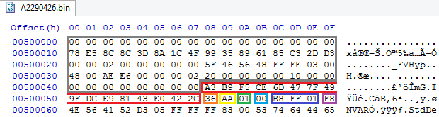
check the above on our file: The first 0x48 bytes of the FV header no longer interests us, but what immediately follows them interests us. It can be seen that there is a file with the GUID CEF5B9A3-476D-497F-9FDC-E98143E0422C, the header checksum is 0x36, the data checksum is 0xAA, which indicates the removed attribute
Now about the sections. All FFS files, except for RAW, should be divided into sections aligned on the border of 4 bytes from the beginning of the file data area. Each type of file has its own requirements for the number and type of sections, but there will be no list of requirements in this article - it is too long and too boring. But section headings, their purpose and types we will now consider.
The minimum section header looks like this:
Size : section size in the same format as in the file header.
Type : type of section.
Sections are divided into two subclasses - encapsulation and leaf. The former may contain sections of other types, while the latter contain directly data. Sections of some types have extended headers, but the beginning always coincides with the general.
For encapsulation sections, 3 types of content are defined:
0x01 -
The full heading EFI_COMPRESSION_SECTION (the words in the title are not mixed up, that’s exactly) looks like this:
UncompressedSize : The size of the decompressed data.
CompressionType : applied compression algorithm.
At the moment there are 2 compression algorithms - Tiano (0x01) and LZMA (0x02). If the section was unpacked without changing the structure, then 0x00 is set as the compression type, and the section size coincides with the size of the packed data. The Tiano algorithm is a combination of LZ77 and the Huffman code by Intel, the compression and decompression code can be taken from the TianoCore project files under BSDL. The LZMA algorithm is too well known to talk about it again, the compression and decompression code is in the LZMA SDK.
Let's continue about the types of encapsulation sections:
0x02 -
0x03 -
There are 12 content types defined for leaf sections:
Let's check the above on our example. The file of the RAW type considered last time does not contain any sections, so let's take another file, namely a PEI module named PchUsb located at offset 0x7AD210:

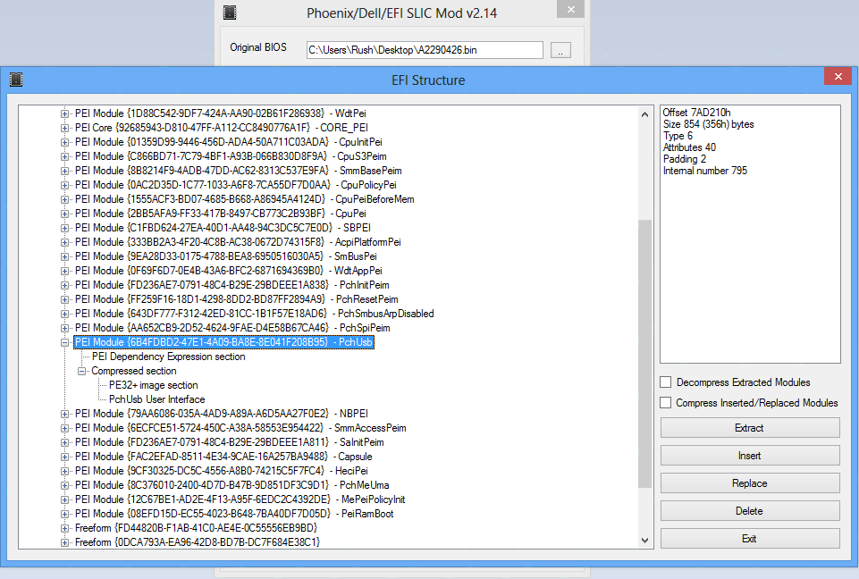
It can be seen that this is really PEIM (file type is 0x06), which contains two sections. The first section of size 0x3A and type PEI_DEPEX (0x1B) contains information about its dependencies. The second section (aligned on the border of 4 bytes) has a size of 0x31A and type COMPRESSED_SECTION (0x01), and the data in it is packed by the LZMA algorithm (0x02) and after unpacking it has a size of 0x558. If you know how to unpack LZMA in your mind, you have already guessed what is inside this section, if not, I will tell you. There are 2 more sections: PE32 with the module executable code and USER_INTERFACE with the file name. You ask, how do I know if I can’t unpack LZMA in my mind? There's an app for that!
This application is called PhoenixTool and its main task is to add SLIC to the UEFI BIOS files, but we are law-abiding people and we will not add SLIC to our BIOS. Of all the functions of the program, we will be interested in the Structure button, available after specifying the BIOS with which we will work. The structure opens in a separate window and presents the UEFI BIOS image as a tree. For each component, information on it and available actions are displayed on the right. The file considered in the example above in this window looks like this:
The program allows limited editing of the file structure, but it is best not to change it, in order to avoid.
For information on how to better edit UEFI executables and what this can do, read the next article.
Thanks for attention.
UEFI Platform Initialization Specification 1.2.1 Errata A, Documents by UEFI Forum
Introduction
I must say right away that in this part of the article I will describe the file formats of version 2, because they are used in all existing BIOSes. In the latest versions of the PI standard , a description of the formats of version 3 has been added, but they are needed for files larger than 16 MB, which are not yet on any board, although Gigabyte has already come close to this point on its Z87 boards. The Descriptor region on all modern Intel motherboards supports no more than 2 chips with a capacity of no more than 16 MB, so the use of version 3 formats is delayed until at least the next generation change of Intel chipsets.
As an example, take the BIOS region from the file version 229 for Zotac Z77-ITX WiFi.
We will need the following programs:
- Hex editor to your taste, I will use HxD
- Utility PhoenixTool v2.xx, which can be downloaded from the topic on the MDL forum
Firmware Volume
The structure of the Firmware Volume and the PI FFS format are described in Volume 3 of the UEFI Platform Initializaton documentation.
Firmware Volume is a logical representation of flash content that has the following attributes:
- Name: the name of the FV and all its parts is their GUID
- Size: includes all data, headers and free space
- Format: file system type inside FV, different types have different GUIDs
- Allignment: requires the first byte of the FV to be aligned at the specified border, a multiple of degree 2. The alignment of the FV should not be weaker than the alignment of all files inside it, except when the flag is set in the header
EFI_FVB_WEAK_ALIGNMENT. In this case, alignment can be done for any power of 2, but this FV can no longer be moved - Attributes of read, write, self-disable read or write protection
- OEM discretionary options
Regardless of the file system used inside the FV, the FV header is standardized and looks like this:
typedef struct {
   UINT8 ZeroVector[16];
   UINT8 FileSystemGuid[16];
   UINT64 FvLength;
   UINT32 Signature;
   UINT32 Attributes;
   UINT16 HeaderLength;
   UINT16 Checksum;
   UINT16 ExtHeaderOffset;
   UINT8 Reserved[1];
   UINT8 Revision;
   EFI_FV_BLOCK_MAP BlockMap[];
} EFI_FIRMWARE_VOLUME_HEADER;
typedef struct {
   UINT32 NumBlocks;
   UINT32 Length;
} EFI_FV_BLOCK_MAP
ZeroVector : at the beginning of FV, 16 bytes are reserved for compatibility with processors whose reset vector is located at the zero address. By the presence of something other than zeros in this block, Boot Firmware Volume can be unmistakably distinguished from the rest.
FileSystemGuid : defines the file system used inside this FV.
FvLength : FV size for all headers.
Signature : used to search for FV and by standard is always 0x4856465F, i.e.
{'_','F','V','H'}. Attributes : the same attributes that we talked about above. There are quite a lot of them, but the most important for us is the aforementioned one
EFI_FVB_WEAK_ALIGNMENT, which makes the FV non-moving if installed, one of a set EFI_FVB_ALIGNMENTfrom EFI_FVB_ALIGNMENT_1to EFI_FVB_ALIGNMENT_2GandEFI_FVB_ERASE_POLARITYindicating which bit is used to erase the flash chip. The rest is needed for code that works with FV as a memory area, and it is useless for us, so we will not list them. HeaderLength : the size of the header excluding the extended header, which is discussed below.
Checksum : 16-bit header checksum. The correct header should add up to 0x0000.
ExtHeaderOffset : offset of the beginning of the extended header. It can contain the GUID of the described FV, a list of OEM file types along with their GUIDs, as well as an electronic signature. At the moment, I have not seen a single FV with a filled extended header, so we will not consider it. If FV does not have an additional header, then 0x0000 is in this field.
Reserved: reserved field, always 0x00.
Revision : The PI standard describes the structure of only one revision - the second, so this field is always 0x02.
BlockMap : a block map stored as a list of structures
EFI_FV_BLOCK_MAPending with the same structure with zeros in both fields. Because Since all modern flash microcircuits are homogeneous (that is, they have blocks of the same size), the entire list usually consists of only two entries. Let's check our example for compliance with the above.
Open our BIOS file in the hex editor and go to offset 0x500000, to the beginning of the BIOS region.
We see that there are 16 zeros at the beginning, there is a file system GUID, the size of this FV is 0x020000, the signature is in place, the attributes are set, the header is 0x48 bytes in size, the checksum is calculated, there is no extended header, reserved fields are in place, and inside this FV has 20 blocks of 0x1000 each, which in total gives exactly the size indicated in the FvLength field.
Most often, the BIOS has several different FVs designed for different purposes, although this is not necessary and you can pack it all into one. The champion in the degree of nesting of FVs and files in each other among all manufacturers of UEFI BIOSes is Intel, where nesting up to 12 levels occurs.
Although theoretically different file systems can be used for FV, in practice only one is used - PI FFS, which we will talk about now.
Firmware File System
This is a flat file system without directories and hierarchy, all of whose files are in the horse directory. Getting a list of files requires going through the FS from start to finish. All files must have a standard-defined header. Files must be aligned on an eight-byte border relative to the beginning of the file system, for alignment over large borders a special file-placeholder is provided.
The standard also describes a special VTF file , which must be present at the end of each FV, but in practice it is present only at the end of the last FV in the BIOS image and is located so that its last byte is also the last in the entire chip. It contains the bootstrap code required for the SEC phase.
File header
The FFS file header is organized as follows:
typedef struct {
 UINT8 Name[16];
 UINT8 HeaderChecksum;
 UINT8 DataChecksum;
 UINT8 Type;
 UINT8 Attributes;
 UINT8 Size[3];
 UINT8 State;
} EFI_FFS_FILE_HEADER;
Name : GUID of the file acting as the name. In one FV there cannot be two files with the same GUID, if these are not PAD files, which are described below.
HeaderChecksum : eight-bit header checksum excluding the DataChecksum field. The correct header should add up to 0x00.
DataChecksum : an eight-bit checksum of the contents of the file, excluding the header. Its calculation is not always required, but only if the attribute is set
FFS_ATTRIB_CHECKSUM, otherwise this field is set to 0xAA. Type: file type. The standard defines 13 standard file types (0x01 - 0x0D), 32 user types for OEM files (0xC0 - 0xDF), 16 user types for debugging (0xE0 - 0xEF) and 16 types specific to the current version of FFS (0xF0 - 0xFF) , of which only 0xF0 is currently used -
EFI_FV_FILETYPE_FFS_PADfor the placeholder file. This special file can have any, including null GUID, null attributes, standard state, and any size. According to the standard, the file must be empty, i.e. all its bits, except for the header bits, must be set to a value
EFI_FVB_ERASE_POLARITY. It is used to align the file following it along the border greater than the standard 8 bytes. The minimum size of the PAD file is equal to the size of the header - 24 bytes. We will return to standard file types.
Attributes : important attributes for us are
FFS_ATTRIB_FIXED, indicating the file's immovability inside the FV and a set of FFS_ATTRIB_DATA_ALIGNMENT, indicating the alignment of the data (not the header) of the file at any boundary. Size : file size along with the header, stored as a 24-bit UINT.
State : file state. This field is used after loading FV into memory and during operations with files inside FV. The status of all valid files inside the BIOS image is 0xF8.
Now back to the file types. For those who have not yet read the one and a half part of this article, I recommend going and reading , otherwise you risk not understanding anything.
As we already know, 13 standard file types are defined, here they are:
| The structure of such a file is completely determined by its user, and nothing is known about it in advance | ||
| Such a file has a sectional structure, but nothing is known about the contents of the sections in advance. | ||
| Security kernel executing code in the SEC phase | ||
| PEI core, aka PEI Foundation | ||
| The core of DXE, aka DXE Foundation | ||
| PEI module | ||
| DXE driver | ||
| Hybrid PEI / DXE Module | ||
| Application. It differs from the DXE driver in that it is not the DXE manager that launches it, but the user. Applications are UEFI Setup, UEFI Shell, BIOS Update, etc. | ||
| SMM module | ||
| Image FV. This is a special file that allows you to embed one FV in another | ||
| SMM / DXE Hybrid Module | ||
| Kernel SMM, aka SMM Init |
Let's
check the above on our file: The first 0x48 bytes of the FV header no longer interests us, but what immediately follows them interests us. It can be seen that there is a file with the GUID CEF5B9A3-476D-497F-9FDC-E98143E0422C, the header checksum is 0x36, the data checksum is 0xAA, which indicates the removed attribute
FFS_ATTRIB_CHECKSUM, type RAW (0x01), without attributes, size 0x1FFB8 and in standard state. Sounds like the truth. Now about the sections. All FFS files, except for RAW, should be divided into sections aligned on the border of 4 bytes from the beginning of the file data area. Each type of file has its own requirements for the number and type of sections, but there will be no list of requirements in this article - it is too long and too boring. But section headings, their purpose and types we will now consider.
Section header
The minimum section header looks like this:
typedef struct {
 UINT8 Size[3];
 UINT8 Type;
} EFI_COMMON_SECTION_HEADER;
Size : section size in the same format as in the file header.
Type : type of section.
Sections are divided into two subclasses - encapsulation and leaf. The former may contain sections of other types, while the latter contain directly data. Sections of some types have extended headers, but the beginning always coincides with the general.
For encapsulation sections, 3 types of content are defined:
0x01 -
EFI_SECTION_COMPRESSION, indicates that the section is compressed according to some algorithm. The full heading EFI_COMPRESSION_SECTION (the words in the title are not mixed up, that’s exactly) looks like this:
typedef struct {
 UINT8 Size[3];
 UINT8 Type;
 UINT32 UncompressedSize;
 UINT8 CompressionType;
} EFI_COMPRESSION_SECTION;
UncompressedSize : The size of the decompressed data.
CompressionType : applied compression algorithm.
At the moment there are 2 compression algorithms - Tiano (0x01) and LZMA (0x02). If the section was unpacked without changing the structure, then 0x00 is set as the compression type, and the section size coincides with the size of the packed data. The Tiano algorithm is a combination of LZ77 and the Huffman code by Intel, the compression and decompression code can be taken from the TianoCore project files under BSDL. The LZMA algorithm is too well known to talk about it again, the compression and decompression code is in the LZMA SDK.
Let's continue about the types of encapsulation sections:
0x02 -
EFI_SECTION_GUID_DEFINED, indicates that the contents of the section should be viewed by the user of the file in accordance with the GUID recorded in it. It is in such a section that various OEM data can be stored, as well as an electronic signature of the section or the entire file. 0x03 -
EFI_SECTION_DISPOSABLE, indicates a section in which data is not important for the operation of the file and can be deleted during rebuilding to save space. In real files, BIOS is not found. There are 12 content types defined for leaf sections:
| 64-bit executable code in PE32 + format with all its headers. The main format for executable code in UEFI. | ||
| 64-bit position-independent executable code. It is used only by some PEI modules, the format is the same as PE32 +, only relocation information is truncated. | ||
| 64-bit executable code used by modules and the PEI core. It differs from PE32 + by a header, which is reduced to save space in the processor cache. Read its description in one and a half part of this article. | ||
| A section describing the dependencies of the DXE driver in which it is located. The format of this section is described in Volume 2 | ||
| Contains the version of the file and optionally a Unicode string with the full version. It is quite rare. | ||
| Contains a unicode-term with the file name. It is very convenient to search for files by the contents of this section. It is used often, but BIOSes are also found without a single file with such a section. | ||
| 16-bit executable code for compatibility with older systems. | ||
| Section with FV image. Inside this FV there may also be a file with such a section, and so on, until the place in the microcircuit runs out. | ||
| The section contains data, the interpretation of which depends on the beginning of the GUID recorded. Used rarely. | ||
| Section with raw data. What to do with them is determined by the one who opened this file. | ||
| A section describing the dependencies of the PEI module in which it resides. The format of this section is described in Volume 1. | ||
| The section describing the dependencies of the SMM driver in which it is located, the format is the same as DXE_DEPEX. |
Let's check the above on our example. The file of the RAW type considered last time does not contain any sections, so let's take another file, namely a PEI module named PchUsb located at offset 0x7AD210:
It can be seen that this is really PEIM (file type is 0x06), which contains two sections. The first section of size 0x3A and type PEI_DEPEX (0x1B) contains information about its dependencies. The second section (aligned on the border of 4 bytes) has a size of 0x31A and type COMPRESSED_SECTION (0x01), and the data in it is packed by the LZMA algorithm (0x02) and after unpacking it has a size of 0x558. If you know how to unpack LZMA in your mind, you have already guessed what is inside this section, if not, I will tell you. There are 2 more sections: PE32 with the module executable code and USER_INTERFACE with the file name. You ask, how do I know if I can’t unpack LZMA in my mind? There's an app for that!
PhoenixTool and conclusion
This application is called PhoenixTool and its main task is to add SLIC to the UEFI BIOS files, but we are law-abiding people and we will not add SLIC to our BIOS. Of all the functions of the program, we will be interested in the Structure button, available after specifying the BIOS with which we will work. The structure opens in a separate window and presents the UEFI BIOS image as a tree. For each component, information on it and available actions are displayed on the right. The file considered in the example above in this window looks like this:
The program allows limited editing of the file structure, but it is best not to change it, in order to avoid.
For information on how to better edit UEFI executables and what this can do, read the next article.
Thanks for attention.
Literature
UEFI Platform Initialization Specification 1.2.1 Errata A, Documents by UEFI Forum