June 29, 2013 at 14:02
Headphone amplifier based on the composite circuit LME49710 + LT1210CT7
Some lyrics
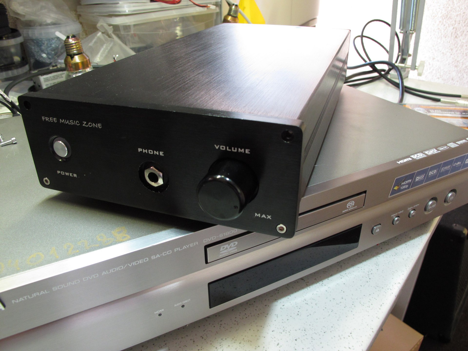
By the nature of my activity, I constantly communicate with professional audio equipment, so the goal of this development was to get a device with high fidelity of reproduction. Therefore, circuitry solutions without OOS were immediately discarded and a composite circuit with great potential was taken as the basis. I had to meet several devices with such a topology, however, in most designs, LT1795 or AD815 devices were used. However, as Dmitry Andronnikov (aka Lynx) mentioned in one of his articles:
even very powerful opamps with TOS, when headphones with a resistance below 50 ... 60 Ohms are connected to their output, operate in a fairly intense mode both in the output current (which leads to an increase in distortion) and in heat generation.
It was decided to attract "heavy artillery", but more on that below.
Device now
Nutrition
I will start, perhaps, from the very end: the first stronghold of protection is a network noise filter and snubber in the secondary windings of the transformer. The snubber's task is to quench the parasitic oscillatory process in the circuit formed by the scattering inductance of the transformer and the capacitance of its secondary winding circuit at the time of locking the diodes. The task of determining the parasitic parameters of transformers is very non-trivial, therefore, Alexei's research (Lexus) was used and the values of 100 Ohm and 0.1 μF were set.
Initially, I intended to install a two-link LC filter using Murata PLA10 and PLH10 series chokes; EMF suppression capacitors - Epcos X2 with a capacity of 0.22 μF and Epcos S20K275 varistor with high absorbed energy - 150 J.
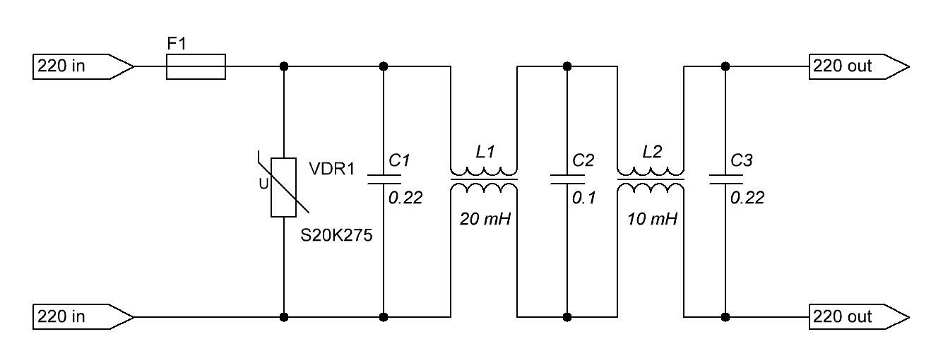
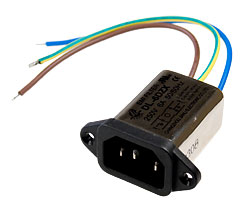
But in the end, it was decided to use ready-made solutions in order to save space in the case:
As stabilizers, M5230L devices manufactured by Mitsubishi Electronic were used [5]. Quite interesting devices that have very low intrinsic noise (many times smaller than that of the widely used LM317 / LM337) in a wide frequency range: 12 μV RMS, 20 Hz - 100 kHz, high temperature stability (0.01% / ° C). But there is one minus - the output current of the IC itself is limited to 30 mA, so to obtain high currents, it is necessary to use external control transistors. The inclusion scheme has no features and is taken from the datasheet - High ripple rejection circuit. Regulating transistors are applied 2SC4793 / 2SA1837 and installed on a common radiator.
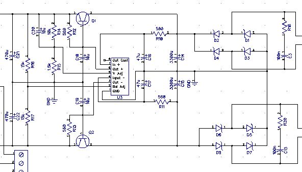
As rectifier applied Schottky SMD diodes 10MQ100. Panasonic FC 3300 uF capacitors, the rest are Elna Silmic and Silmic II series. Initially, it was planned to install additional capacities near LT1210, but when wiring the board, it was decided to refuse them, since the output capacities of the PSU were in close proximity to the consumer. When using Elna capacitors even at the stage of designing a printed circuit board, it is necessary to clarify their sizes on the manufacturer's website, since these capacitors have several times larger dimensions than "ordinary" ones:
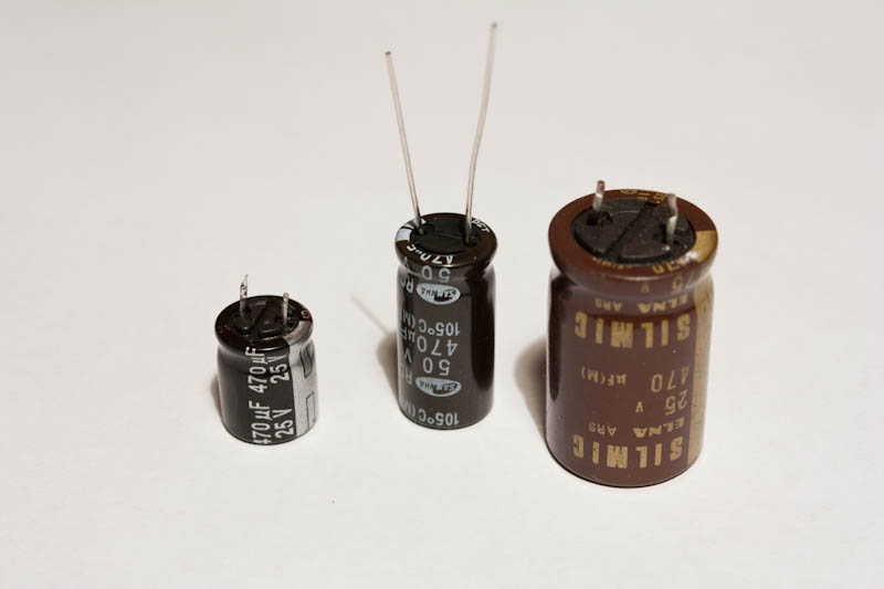
Amplifier
The composite circuit has a large loop gain, the output stage on a powerful op-amp is covered by its own OS loop, which allows for fairly low distortion when working for various types of loads.

The output stage uses high-speed op amps with current operating system LT1210CT7 manufactured by Linear in the TO220 package, which provides much better heat dissipation than other versions of the packages offered by the manufacturer. These opamps can provide a long-term current of 1.1A (2A at the peak), which makes it easy to work on a load with a low resistance. The gain of the output op-amp is 2, but can easily be reduced to 1, or increased. The choice of resistor ratings in the OS circuit of an op amp with a TOC is somewhat more complicated than for an op amp with an op amp in terms of voltage: the stability of the circuit directly depends on its rating. Decreasing the Rf rating increases the operating frequency band, but degrades stability; decreasing it increases stability and narrows the operating range. The resistors in the OS circuit (1.5 kΩ) are selected in such a way as to ensure maximum stability. Compensation capacitors (C4, C23) provide stability when working on capacitive loads. In general, the manufacturer promises stable operation at a capacitive load of up to 10,000 pF!

A bit about the thermal regime. In datasheet [3] are given (which is not very common) examples of calculations of the thermal regime are given. Chips are mounted on individual HS211 radiators with a thermal resistance of 7.5 ° C / W. The thermal resistance of the crystal-case is 5 ° C / W. Not knowing the exact thermal resistance of the insulating pad, it was taken to be 2 ° C / W for calculations (according to some data found on the Internet).
With a load of 16 Ohm (although professional headphones are rarely with a resistance below 50-60 Ohms) and an output signal of 4V RMS (which corresponds to 5.6V amplitude voltage), the microcircuit will dissipate 2W of heat (the current consumption in this mode is slightly over 100 mA). At an ambient temperature of 25 ° C, the crystal will heat up no more than 65 ° C.
Since our device will be in a closed case, the temperature inside can reach pretty decent values of 50-60 ° C. As a result, we obtain a crystal temperature of the order of 100-110 ° C, which is quite acceptable. But this is on a sinusoidal signal, on a music signal (although I had to “see” phonograms with RMS -3 db :-)) the heating will be much less.
As the first “step”, a device manufactured by another company was chosen - LME49710 from Texas Instrument [4], which has excellent characteristics: low level of all types of distortion, very low noise level (0.34 μV RMS @ 20Hz - 20,000 Hz), low level bias (± 0.05 mV), large open gain (140 dB) and high CMRR and PSRR (120 and 125 dB).
However, in the process of setting up the device, one instance of this op-amp was caught, when installed, the constant voltage at the output was about 14 mV; after some deliberation another device was installed (out of 10 purchased) - everything returned to normal.
Board as a structural element
When using such a high-speed op-amp as LT1210, which has a slew rate of 900 V / μs, it is worth paying special attention to the topology of the printed circuit board, since in high-speed analog circuits it can significantly affect the quality of the device. The board should be designed to minimize the impact on the operation of the circuit. More details about the topology of printed circuit boards can be found in the books [1] and [2].
The amplifier is made on a double-sided printed circuit board, the lower layer of which is reserved for the GND polygon, of course, in the process of wiring, some circuits nevertheless ended up on the lower layer, but they have a small length. This board topology was chosen to minimize the ground impedance necessary for the stable operation of high-speed op amps. The vulnerability of the op-amp inverting inputs to the ground capacitance was also taken into account, since even a capacitance of 1 pF can lead to an increase in the op-amp transmission coefficient at frequencies close to the maximum. The most obvious solution to this problem is to shorten the length of the conductor. Another, less obvious, is a decrease in its width. As a result, the application of conductors with a thickness of 0.3 mm to the inverting input of the op amp gives a capacitance of about 0.1 pF depending on the dielectric constant of the board material (for FR-4 it is from 4 to 5).

During assembly and configuration
A transformer with four secondary windings with voltages of 14 V and a current of 500 mA, which was specially ordered at the factory for this project, is used to power the device. Volume control I used ALPS RK27 with a resistance of 10 kOhm. The case was purchased in China.

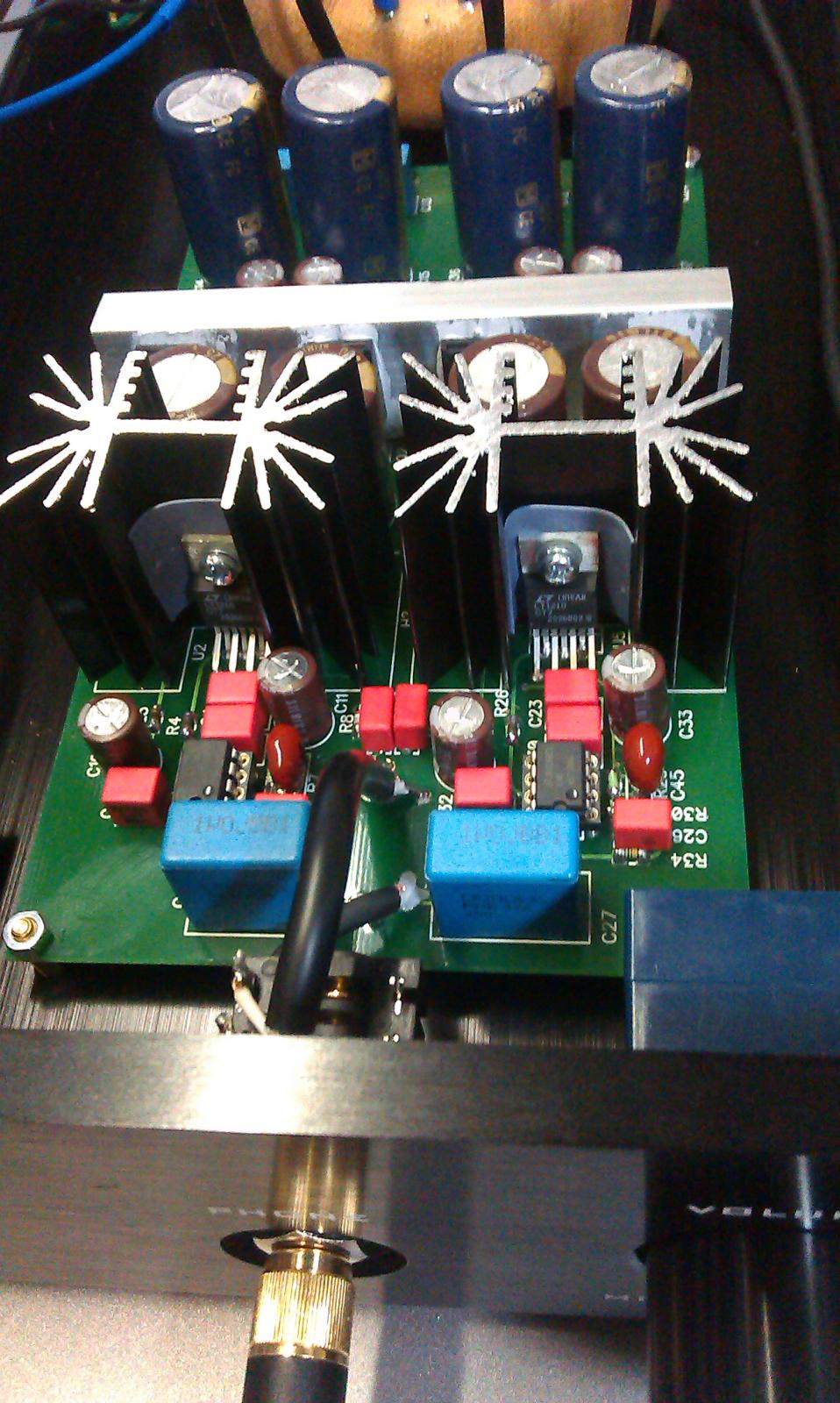
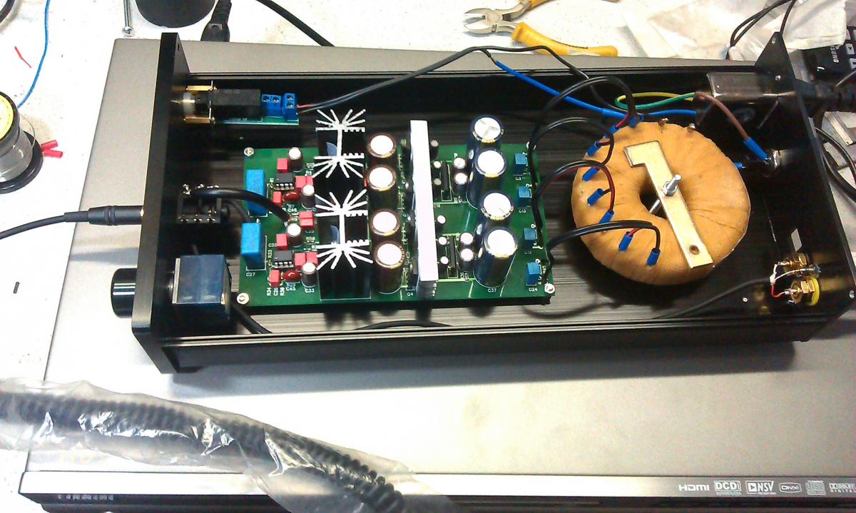
Unfortunately at this point, nothing but the phone was at hand.
And now the measurements
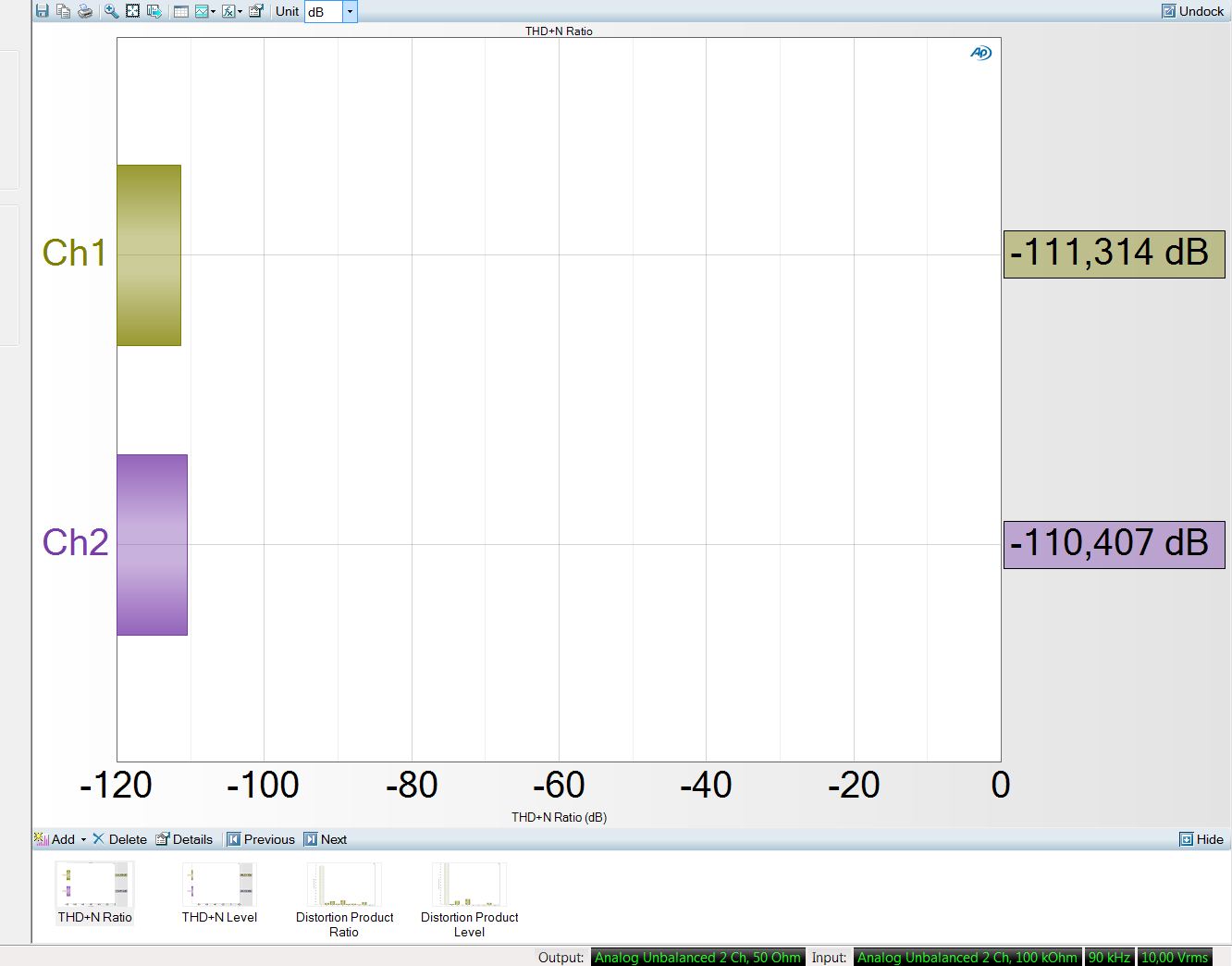
After assembly and listening, measurements were taken using the Audio Precision AP586 complex :



Literature:
- Bruce Carter and Ron Mancini. “Operational Amplifiers for Everyone.”
- Walt Jung. Op Amp Applications Handbook
- LT1210 datasheet
- LME49710 datasheet
- M5230L datasheet