Just add meat or fashion embedding

the essence
With the advent of affordable ARM and MIPS solutions, on which you can install Linux or WinCE, amateur embedding has reached a qualitatively new level (in general, it has long been there, but not on such a wide scale as today). The emergence of such massive software products as Android, very much popularized processors with non-x86 architecture, opened up new opportunities for the general public in the form of lower prices for high-speed hardware and provided access to the information that was previously disseminated exclusively after the signing of the NDA.
And .nix pieces of iron seem to be good for everyone: routers, Raspberry Pi and various devices a la MK802. For many, they steer production and home processes, robots and coffee makers. But, the low reaction rate to external influences, somewhat limits the use of such systems in embedding. Such functions that are completely absent in such devices (meaning consumer goods, rather than specialized solutions once or twice ) can include PWM with emergency shutdown, high-speed PID controller, quadrature encoder processing, and many, many others. All these things require a degree of real time.
A brief description of some ways to add muscle, a little theory, personal thoughts and of course, a decision from me under the cut.
Part one. Theory and Reflections
Let's look at the existing iron ways to solve the problem of "smart, but frail." There are several options for such iron:
1. 74xx, 40xx and other many-legged
Logics. Just the logic.
Time-tested option for expanding logical functions.
Simple logic will allow you to collect several signals into one, parse one into several and form a digestible signal from the garbage. And he will do it all very quickly.
The disadvantage of this method is the large dimensions of the circuit, which tend to grow to incredible sizes with increasing complexity.
Point two follows from the first, but I set it apart.
This is also logic, but the logic is programmable.
2. CPLD and FPGA
There are practically no drawbacks to this method of iron expansion of functions. It is widespread in practice, but a rather high entry threshold, a rather high price for glands and some (and in the case of FPGA even quite specific) monstrosity do not allow using this approach where you do not need to count flops and steer tens and hundreds of logical levels .
Given that our smart hardware is trained to communicate normally through RS-232 or SPI, and much less willingly through GPIO, we do not make a comforting conclusion: in order for our silly fast logic to communicate with a smart slow host, we need a miracle device .

habitat marvel
A miracle device should be able to receive a command from the host that is understandable to the host and issue it in a form that is understandable to logic, as well as receive data in a form convenient for the logic, and send it to the host in a convenient form for it.
The technology is somewhat confusing, but it perfectly describes the process of communicating stupid iron with smart.
It is customary to use a microcontroller as a miracle device (in the case of FPGAs, you can often do without it).
3. Microcontroller
Of course, the microcontroller! This resource has already seen successful precedents for crossing a router as the “smartest” and a microcontroller as an exoskeleton. The trend of crossing androids with Arduino or STM32 has also become very noticeable in recent weeks. Actually, this trend prompted to write an article.
With the advent of MK in this circuit, the application of logic as a workforce becomes unclear, but a close examination of the electrical processes occurring in the system with buttons, relays, power converters, and other control and executive devices does not completely abandon logic in some cases.
One of such cases may be an automaton with a certain number of parallel inputs. Suppose that the desired state of the inputs is deterministic and does not just look like “all to zero,” but has some kind of complex form. In this case, the microcontroller has no choice but to monitor this very number of inputs in the work cycle and ... do nothing else. And even in this particular case, the microcontroller does not provide comparable performance, because each individual change in the state of the port, micron will be approached separately. He will need to first process the interrupt, read the contents of the port (or several), compare the status with the one sought, and make his resume write to the port. Even single-cycle devices will spend a lot of time on this process. A simple logic circuit will solve this problem head on, indiscriminately.
Part two. Or how I came to such a life
While working in production as a “solver of production jambs”, I often had to deal with the need to solder, program, and flash something. Whether it was controlling a valve for recruiting water into a reserve tank, or an automatic switch of heating pumps according to a given program, these were autonomous devices built on MK. And in those prehistoric times (5-6 years ago) there were almost no automation options available besides an industrial PLC and an improvised device on the MK.
Agree, because the program that serves the pump (pump if the water level is lower - do not pump if higher) is not worth the whole PLC for 100+ dollars. Anticipating the comments of vigorous circuit designers, I hasten to declare that MK is also a redundant candidate for this program, but has undeniable advantages over the analog circuit - human-programmable time and thresholds (instead of applying math magic to capacitors and resistors).
And since a naked MK was chosen to solve the problem, besides the obvious savings, I also get the obvious smut in the form of soldering. The balance of costs and problems was decisive in choosing a solution. Particularly critical processes and work in poor electromagnetic conditions, as it should be, were trusted by the PLC without any reverence towards homemade work.
The appearance of the notorious routers for $ 20 allowed a fresh look at the automation of non-critical processes. The experience was twofold. On the one hand, for a penny, I got a system that speaks to me in an almost human language. On the other hand, a device that is fundamentally incapable of working with discrete signals at an acceptable level in speed. This imposed its limitations in the application of new technology. Further popularization of arduino-like and motherboards similar to STM32 Discovery predetermined a bunch of Linux devices with a low-level exoskeleton in the form of an 8, 16 or 32-bit MK (plus logic, op-amp, and other bare-metal hardware).
Simple devices were made according to the old-new scheme:
1) We take the Arduino Nano
2) We tie the infrastructure
3) ???
4) PROFIT!
As before, all this was suitable only for office use and in the presence of a huge amount of empty space. As for small-sized devices, everything was bad here. And if a simple device that did not need to update the firmware could be done on a bare MK, then it was dumb to install a bare MK in a device for which the firmware was buggy for which I was not really sure (but it was necessary yesterday). Firstly, a firmware is needed to upgrade the firmware. Secondly ... however, the first point was enough for me. I generally do not like programmers in any form. For me, the best programmer is a USB wire.
Constant dissatisfaction with these nuances has generated a burning desire to unify, unify, unify ...
Part three. Three weeks ago
Three weeks ago, I put into production another project (my main activity is the mass production of electronics), and the next loomed only after about two weeks. Two weeks browsing the internet? Hmm ... tempting ... but something hit my head, and the word "unification" surfaced in my memory. And with him the old dissatisfaction with the life of the embedder. On such a depressing note, I set myself the task: to create at least something to get positive in front of a new project, to satisfy the FWM and to improve the quality of life of earthlings in two weeks.
To implement such ambitious plans, no less ambitious iron was needed. And it was found among products widely known in narrow circles of the company Microchip. This is a relatively new MK PIC16F1509. Here, I must make a theoretical digression and talk about the nature of this force majeure that made modern people use non 32bit MK.
So, the periphery.
In addition to the standard peripherals (USART | SPI | I2C, 4xPWM, 10bit ADC, 5 bit DAC, 3 Timers, a crystal temperature sensor and, of course, GPIO), there were interesting innovations among entry-level MCs. These innovations categorically tipped the scales from the fashionable 32bit STM to the non-fashionable 8bit Microchip.
CLC (Configurable Logic Cell)
Programmable logic on a MK chip.
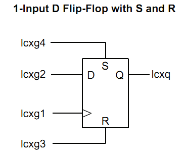
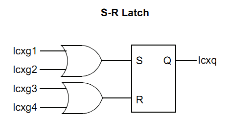
Each of the four modules has the form:
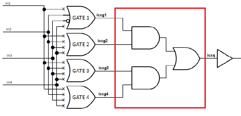
On the left are four inputs to which you can connect the physical conclusions of the MK, interrupts from timers, comparators, PWM, a generator, and in general much of what is inside and outside the MK. The set of sources for one module includes 16 signals, but there are differences between the sets for each of the four modules. In particular, the various physical conclusions of MK. Next on the diagram is the switch. Signals can be connected either directly or with inversion. The outputs of the OR elements going after the switch are also controlled (direct / inverse). At the very end to the right is the module output, which can be inverted, output to the physical output of the MK, or wound to the input of the CLC. The output generates an interrupt on the edge or on the fall (as you configure).
A red rectangle denotes a variable logical function, which, in addition to the already presented AND-OR, has 7 more options:

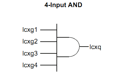
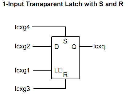
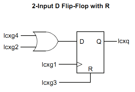

Unfortunately, the purpose of this article is not a literacy campaign on digital circuitry, so there is nothing to comment on here - the illustrations speak for themselves. I only note that all this economy is configured directly in the code, by the banal assignment of values to the registers as the most ordinary peripherals such as a timer or GPIO. To facilitate the configuration of this not very simple figovina, there is a GUI:
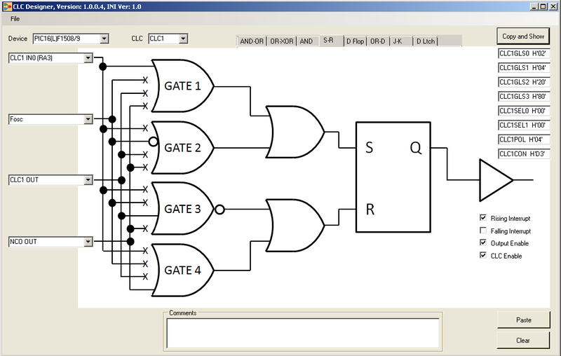
With a GUI, everything becomes extremely simple. In the upper right corner you can see the values of the registers, but you can just generate a ready-made assembler or C code. I promise to return to this curious periphery and use cases next time. And for those interested, I recommend a visitthis page .
NCO (Numerically Controlled Oscillator)
In fact, it is a frequency synthesizer up to 500 kHz (when clocked from an internal 16 MHz generator) with a tuning step from 0.03 Hz (when clocked from an internal 31 kHz generator) to 15 Hz (16 MHz clock) It
can generate a meander and PWM.
One application of NCO and CLC ( Appnote ) provides 16bit PWM in the duty cycle range from 0% to 100% at a PWM frequency of 500kHz.
CWG (Complementary Waveform Generator)
Programmable half-bridge driver.
Several signal sources to choose from (CLC1, NCO, PWM and comparators).
This is an extremely useful thing, and in many cases it can save the developer from fire, smoke and the bitterness of loss. With the prevention of these troubles, the hardware control of dead time is called to fight.
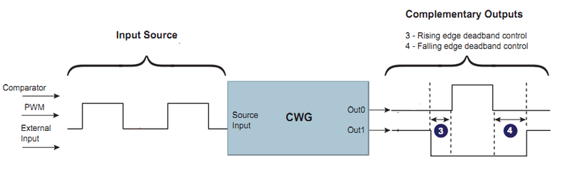
Each of the transistors of the pair opens strictly when the second is probably already closed. This is done to eliminate the through current, which leads to beautiful, but sometimes expensive special effects. The time given to the previous transistor to close (deadtime) is adjusted separately for the leading and trailing edges. Also, forced stop signals are called upon to deal with special effects, of which there are four: a special output GPIO, CLC2, and both comparators. Considering that we can supply “something else” to the input of CLC2, we get a fairly extensive list of options for high-speed emergency stop of the driver without any involvement of the kernel. From timeouts to analog and logic levels.
On this note, perhaps it is time to tie up with theory and go directly to practice.
Part Four Development and production
Having decided on the MK, I begin to think through the rest of the construct. I wanted the smallest possible floor space. Having lost several options in my head, I settled on a solution that occupies the area of the microcircuit in the DIP 20 (!) Package. Further, already starting from overall requirements, I chose the element base. As a USB-TTL converter, the well-known CP2102 chip is used (QFN case and quartz are not needed), the USB connector was selected vertical, and the microcontroller in the QFN case. All this stuff was immediately purchased at the Mauser.
With the board, too, did not stand on ceremony. She, in view of her extreme simplicity, was divorced in about an hour. The power leads are pointedly placed in the same place where they are located on the 74xx logic chips. Next, I ordered the manufacture of several pieces at the factory and began to wait. While waiting, the work on the module was exclusively mental ... dreamy, I would say.
By the time all the iron was received on hand, the initial two weeks had almost come to an end. I risked overwhelming my own terms, and getting a large portion of depression, which is so harmful to a 30-year-old male body.
As a matter of urgency, as a bootloader, without which no microcontroller device can already do, the worked out option was chosen - ds30 Loader. In its free version, it only allows you to download the compiled hex via UART to MK and at the same time has a convenient GUI (well, there is a console utility for connoisseurs).
Result on the photo:
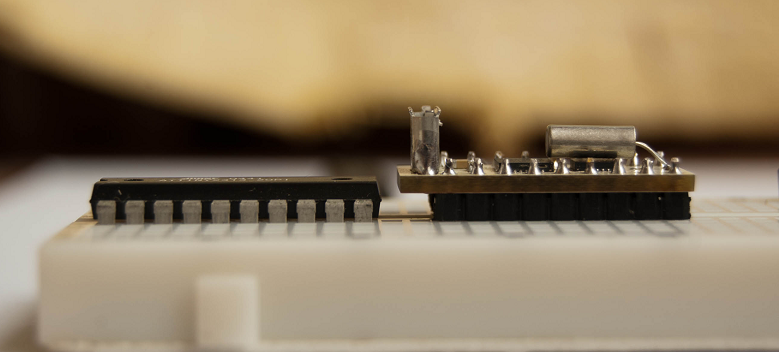
in profile next to DIP20 (ATtiny2313),
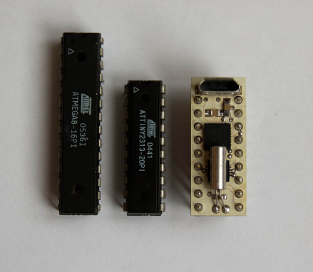
top view
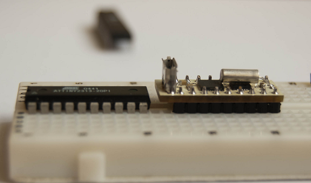
perspective ...
MK works from the built-in 16MHz generator. Quartz, which is visible in the photo, for software RTC, which is implemented on Timer1. 18 of the 20 pins of the MK are directly connected to the connector (two are occupied by quartz), including RX and TX for direct connection of the RS-232 TTL. If you use only this same RS-232 TTL, then the board takes a degenerate form
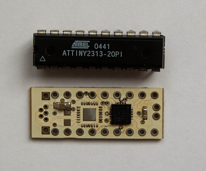
it looks like a poorly laundered board
Instead of a conclusion
The result was a pretty cute trinket, which, nevertheless, can greatly facilitate communication with the cruel outside world for Linux-powered devices. Since the competition with arduino in this form factor is huge, I focused on dimensions and unique peripherals.
At the moment, the firmware includes the inclusion and adjustment of the parameters of several peripheral modules using RS-232 commands. These are PWM, DAC, GPIO and partially CLC. You can also find out what time it is and read ADC (both external inputs and the crystal temperature sensor). That is, it already copes with some functions of a fast exoskeleton for a slow OS.
But even if absolutely all peripherals work to the tune of RS-232 (there is no special reason for this), this will not be the limit. Now it’s already clear that this functionality will occupy far from all the place in the MK’s memory, and the most suitable way to utilize the remaining few kilobytes, I think, would be a limited interpreter of the SFC graphical language for the simplest automation within 30-50 steps, as well as software modules, such as PID, the expansion of the number of inputs / outputs through I2C expanders , which will enable the unified connection of displays and keyboards.
The main sources of inspiration were habrahabr, some kind of Chinese site with android balalaikals of 50 bucks, and the site www.microchip.com The
world is for everyone.