Network Virtualization in Hyper-V. Concept
In Windows Server 2012 there was a network virtualization technology (Network Virtualization, NV), providing the ability to virtualize on a fundamentally new level - the level of the network segment. Unlike the usual server-side virtualization, NV allows you to virtualize IP subnets and completely hide the real IP addressing used in your infrastructure from virtual machines (VMs) and applications inside the VM. At the same time, VMs can still interact with each other, with other physical hosts, with hosts on other subnets.
From a technological point of view, network virtualization is a rather complicated mechanism, therefore, perhaps, a more or less complete overview of this technology in a single post will fail. Today we will discuss the concept and architecture, in the next post I will focus on configuring NV, then we will separately discuss the organization of external access to VMs running on a virtualized network.
Let's start with the fundamental question: “Why do we need network virtualization?”
In the case of server virtualization with a few caveats, the OS inside the VM works as if it were installed on a physical server and was the only OS on this equipment. Such an abstraction allows you to run multiple isolated instances of virtual servers on one physical. By analogy, network virtualization leads to the fact that a virtual, or rather, in this context, virtualized network functions as if it were a physical network. Accordingly, this level of virtualization allows you to create and use several virtual networks, possibly with overlapping or even completely matching IP address spaces, on the same physical network infrastructure. And this network infrastructure, generally speaking, can include an arbitrary number of physical servers and network equipment (see fig. below).

In the figure, virtual machines from the blue network and the red network belonging to different departments or organizations can use the same IP addresses, can be run on the same or different physical hosts, but on the one hand, they will completely isolated from each other, and, on the other hand, without any problems they will interact with other network objects (real or virtual) of their department or their organization. This implies the purpose of NV technology, the advantages and main scenarios of its application.
Greater flexibility in hosting VMs within the data center
NV provides some freedom in hosting VMs within the data center. In particular, hosting a VM involves configuring the IP address corresponding to the physical network segment and configuring the VLAN to provide isolation. Since NV allows coexistence on the same VM host with matching IP addresses, we are no longer bound by the IP addressing scheme used in the data center and we are not limited by the restrictions imposed by VLAN.
Simplified transfer of VMs to the cloud
Since using the virtualization of the network, the IP address and configuration of the VMs remain unchanged, this greatly simplifies the process of transferring VMs to the organization’s data center, to the host’s cloud, or to the public cloud. Both application clients and IT administrators continue to use their tools to interact with the VM / application without reconfiguration.
Live Migration beyond the subnet
Dynamic VM migration is limited to the IP subnet (or VLANs). If you migrate the VM to a different subnet, you will need to reconfigure the IP inside the guest OS with all the ensuing consequences. However, if dynamic migration is performed between two hosts with Windows Server 2012 with NV enabled, the hosts can be located in different segments of the physical network, while network virtualization will ensure the continuity of network communications of the moved VM.
Increased utilization of physical host and network resources
The absence of dependence on IP addressing and VLANs allows loading physical hosts more evenly and utilizing available resources more efficiently. It should be noted that NV supports VLAN, and you can combine both methods of isolation, for example, by isolating NV traffic in a dedicated VLAN.
When configuring NV, a pair of IP addresses is associated with each virtual network adapter (vNIC):
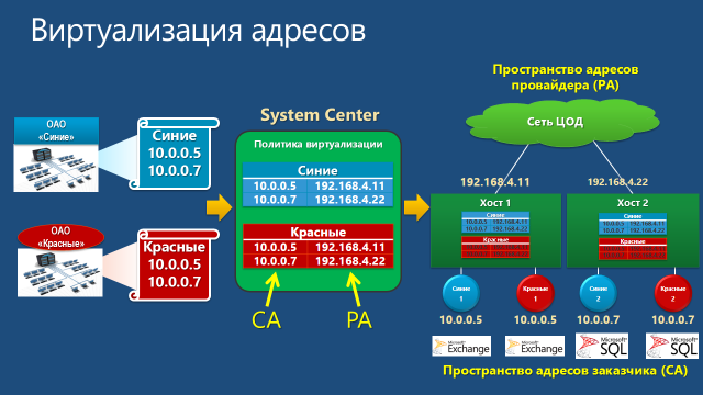
In the process of network interaction, the VM forms a packet with the addresses of the sender and receiver from the CA space. Such a packet leaves the VM and the Hyper-V host is packed into a packet with the addresses of the sender and receiver from the PA space. PA addresses are determined based on a virtualization policy table. After that, the packet is transmitted over the physical network. The Hyper-V host that received the packet, on the basis of the same virtualization policy table, performs the reverse procedure: it extracts the source packet, determines the destination VM and redirects the source packet with the CA addresses of the desired VM.
Thus, network virtualization ultimately boils down to the virtualization of addresses used by virtual machines. In turn, address virtualization in Hyper-V Windows Server 2012 is possible using two mechanisms: Generic Routing Encapsulation and IP Rewrite. Let us consider briefly each of them.
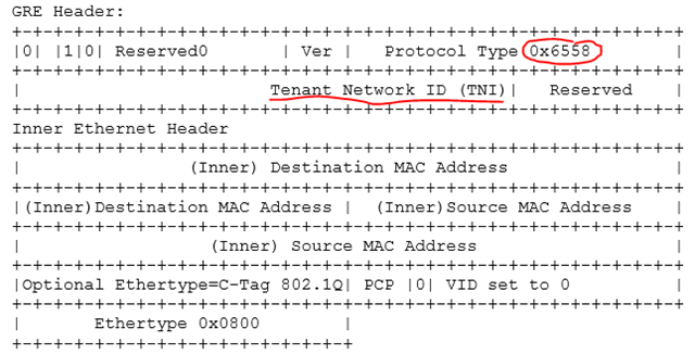
In the first mechanism, the source packet with CA addresses is encapsulated in the GRE structure (Generic Routing Encapsulation, see RFC 2890 ), which is packed into an IP packet with the necessary PA addresses. A unique virtual subnet identifier (Virtual Subnet ID, “GRE Key” field in the figure), to which the source packet belongs, and the MAC addresses of the virtual network adapters of the sender and recipient VMs are also added to the GRE header.

The subnet identifier allows the recipient host to correctly determine the VM for which the packet is intended, even in the case of possible coincidence of the CA addresses in the VMs of different customers. The second important feature of this mechanism is that, regardless of the number of VMs running on the host, one PA address is enough to transfer packets from any VM. This significantly affects the scalability of the solution when using the GRE address virtualization mechanism. Finally, it should be noted that the described scheme is fully compatible with existing network equipment and does not require any updating of network adapters, switches or routers.
However, in the future, it would not be out of place for a switch or router to analyze the Virtual Subnet ID field of a packet, and the administrator could configure the appropriate rules for switching or routing packets based on this field. Or, for example, to take care of all the tasks associated with packing-unpacking GRE, the network adapter. To this end, Microsoft, together with partners, developed the NVGRE standard , Network Virtualization using Generic Routing Encapsulation, which is now in the IETF Draft stage. In particular, this standard regulates the 24-bit Tenant Network Identifier (TNI) field for storing the subnet identifier, protocol type 0x6558, indicating the NVGRE packet, and other nuances.
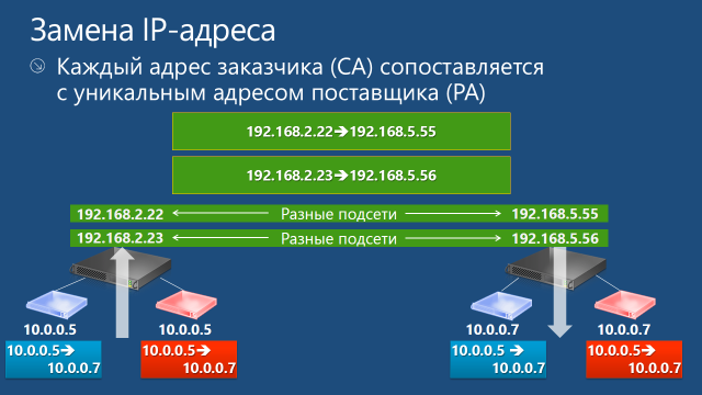
The second mechanism in its ideology is somewhat simpler. Each CA address is assigned a unique PA address. When a packet leaves the VM, the Hyper-V host replaces the CA addresses with PA addresses in the IP packet header and sends the packet to the network. The receiving host performs the reverse address replacement and delivers the VM packet. As follows from the described algorithm, on each physical host with the Hyper-V role it is necessary to configure as many PA addresses as the CA addresses are used in all virtual machines running on this host that use network virtualization.
Encapsulating packages with GRE requires additional overhead. Therefore, for scenarios with high requirements for channel bandwidth, for example, for VMs that actively use a 10Gbps adapter, IP Rewrite is also recommended. For most other cases, the GRE mechanism is optimal. Well, with the advent of equipment supporting NVGRE, this mechanism will not be inferior to IP Rewrite in performance.
In Hyper-V Network Virtualization terminology, a customer is the “owner” of a group of VMs deployed in a data center. In practice, if we are talking about the data center of a hosting service provider, such a customer may be a company or organization. If we are talking about a private cloud, then the customer, as a rule, is the department or department of the organization. In any case, the customer may own one or more networks (Customer Network), and each such network consists of one or more virtual subnets (Virtual Subnet).
Customer network
Virtual subnet
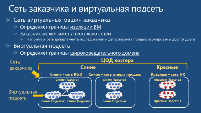
The application of these two concepts allows the customer to transfer their network topology to the cloud. In fig. Below are two of Siniye’s networks - an R&D network and a sales network. Initially, these networks are isolated and should not interact with each other. Since during transfer to the Hyper-V Network Virtualization environment these networks are assigned different RDIDs, the VMs of these networks cannot "see" each other. At the same time, for example, VMs from virtual subnets 1, 2, and 3 of the R&D network can exchange packets.
NV is available only in Windows Server 2012.
On hosts with Hyper-V Network Virtualization, a virtualization policy must be supported, which actually sets and stores information about CA and PA spaces, RDIDs and VSIDs, and address virtualization mechanisms. Windows Server 2012 contains a set of programming interfaces (APIs) through which software can manage all aspects of NV. In the simplest case, such management software can be PowerShell scripts; in an industrial scenario, this role is played by System Center 2012 Virtual Machine Manager SP1 (VMM). I draw your attention to the fact that it was with the release of SP1 that System Center 2012 introduced support for Windows Server 2012, and therefore NV.
The settings specified in the virtualization policy are directly applied by the Network Filter Interface Specification (NDIS) driver called Windows Network Virtualization (WNV). The WNV filter is located below the Hyper-V Extensible Switch. This means that the Hyper-V switch and all its extensions (if any) work with CA addresses and do not know anything about PA addresses. However, the VSIDs are accessible to the switch and extensions, so the Hyper-V Extensible Switch is able to distinguish, for example, 10.0.0.5 CA addresses belonging to different customers.
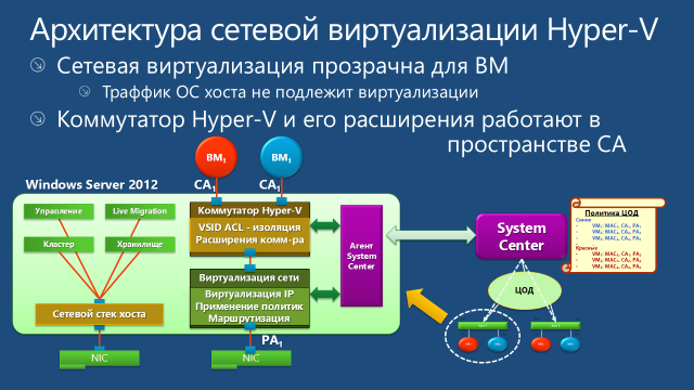
If network virtualization is enabled for the VM, then for the Hyper-V Extensible Switch ports to which the virtual network adapters of this VM are connected, the hypervisor includes Access Control List (ACLs). I talked more about ACL here. The ACL specifies the VSID of the virtual subnet to which the VM belongs. Any packets arriving at this switch port with a VSID other than that specified in the ACL are ignored.
Taking this logic into account, packet movement is as follows. An outgoing packet from the VM through the Hyper-V Extensible Switch port enters the WNV filter, which analyzes the NV virtualization policy and applies the necessary operations to the packet (replacing the IP address or packing in GRE), after which the packet is sent to the network.
On the receiving side, the incoming packet enters the WNV filter, which analyzes the NV virtualization policy. If the incoming packet is a GRE packet, the filter reads the VSID field from the GRE header, extracts the original IP packet and sends it along with the VSID to the Hyper-V Extensible Switch port to which the vNIC of the virtual machine is connected with the CA address corresponding to the destination address in the header of the source IP packet. If the transmitted VSID matches the VSID in the ACL of this port, the switch passes the packet to the virtual machine. If the virtualization mechanism used is IP Rewrite, the filter, based on the information from the virtualization policy, changes the PA addresses in the packet to CA addresses, it identifies the VSID from the same pairs of PA and CA addresses, and the packet with the CA addresses along with the VSID sends to the appropriate Hyper-V Extensible Switch port.
The described logic is applied when a packet is transferred between VMs located on the same or different hosts with Windows Server 2012 and the elevated Hyper-V role. The situation will become somewhat more complicated if the package from the VM, in which, for example, a certain business application is running, must reach the workstation with the client part of this business application. In this case, we will need to configure Hyper-V Network Virtualization Gateway, which we will discuss separately.
In the next post I will tell you how to configure NV using: 1) PowerShell scripts, 2) VMM.
In the meantime, you can:
Hope the material was helpful.
Thanks!
From a technological point of view, network virtualization is a rather complicated mechanism, therefore, perhaps, a more or less complete overview of this technology in a single post will fail. Today we will discuss the concept and architecture, in the next post I will focus on configuring NV, then we will separately discuss the organization of external access to VMs running on a virtualized network.
Let's start with the fundamental question: “Why do we need network virtualization?”
What is network virtualization for?
In the case of server virtualization with a few caveats, the OS inside the VM works as if it were installed on a physical server and was the only OS on this equipment. Such an abstraction allows you to run multiple isolated instances of virtual servers on one physical. By analogy, network virtualization leads to the fact that a virtual, or rather, in this context, virtualized network functions as if it were a physical network. Accordingly, this level of virtualization allows you to create and use several virtual networks, possibly with overlapping or even completely matching IP address spaces, on the same physical network infrastructure. And this network infrastructure, generally speaking, can include an arbitrary number of physical servers and network equipment (see fig. below).

In the figure, virtual machines from the blue network and the red network belonging to different departments or organizations can use the same IP addresses, can be run on the same or different physical hosts, but on the one hand, they will completely isolated from each other, and, on the other hand, without any problems they will interact with other network objects (real or virtual) of their department or their organization. This implies the purpose of NV technology, the advantages and main scenarios of its application.
Greater flexibility in hosting VMs within the data center
NV provides some freedom in hosting VMs within the data center. In particular, hosting a VM involves configuring the IP address corresponding to the physical network segment and configuring the VLAN to provide isolation. Since NV allows coexistence on the same VM host with matching IP addresses, we are no longer bound by the IP addressing scheme used in the data center and we are not limited by the restrictions imposed by VLAN.
Simplified transfer of VMs to the cloud
Since using the virtualization of the network, the IP address and configuration of the VMs remain unchanged, this greatly simplifies the process of transferring VMs to the organization’s data center, to the host’s cloud, or to the public cloud. Both application clients and IT administrators continue to use their tools to interact with the VM / application without reconfiguration.
Live Migration beyond the subnet
Dynamic VM migration is limited to the IP subnet (or VLANs). If you migrate the VM to a different subnet, you will need to reconfigure the IP inside the guest OS with all the ensuing consequences. However, if dynamic migration is performed between two hosts with Windows Server 2012 with NV enabled, the hosts can be located in different segments of the physical network, while network virtualization will ensure the continuity of network communications of the moved VM.
Increased utilization of physical host and network resources
The absence of dependence on IP addressing and VLANs allows loading physical hosts more evenly and utilizing available resources more efficiently. It should be noted that NV supports VLAN, and you can combine both methods of isolation, for example, by isolating NV traffic in a dedicated VLAN.
Hyper-V Network Virtualization Concept
When configuring NV, a pair of IP addresses is associated with each virtual network adapter (vNIC):
- Customer Address (CA) . The address configured by the customer within the VM. This address is visible to the VM itself and the OS inside it, at this address the VM is visible to the customer’s infrastructure, this address does not change when the VM moves within the data center, or beyond.
- Provider Address (PA) . The address assigned by the data center administrator or hoster based on the physical network infrastructure. This address is used when transmitting packets over a network between Hyper-V hosts running VMs and configured NV technology. This address is visible in the physical network segment, but not visible for the VM and guest OS.

In the process of network interaction, the VM forms a packet with the addresses of the sender and receiver from the CA space. Such a packet leaves the VM and the Hyper-V host is packed into a packet with the addresses of the sender and receiver from the PA space. PA addresses are determined based on a virtualization policy table. After that, the packet is transmitted over the physical network. The Hyper-V host that received the packet, on the basis of the same virtualization policy table, performs the reverse procedure: it extracts the source packet, determines the destination VM and redirects the source packet with the CA addresses of the desired VM.
Thus, network virtualization ultimately boils down to the virtualization of addresses used by virtual machines. In turn, address virtualization in Hyper-V Windows Server 2012 is possible using two mechanisms: Generic Routing Encapsulation and IP Rewrite. Let us consider briefly each of them.
Generic Routing Encapsulation
In the first mechanism, the source packet with CA addresses is encapsulated in the GRE structure (Generic Routing Encapsulation, see RFC 2890 ), which is packed into an IP packet with the necessary PA addresses. A unique virtual subnet identifier (Virtual Subnet ID, “GRE Key” field in the figure), to which the source packet belongs, and the MAC addresses of the virtual network adapters of the sender and recipient VMs are also added to the GRE header.

The subnet identifier allows the recipient host to correctly determine the VM for which the packet is intended, even in the case of possible coincidence of the CA addresses in the VMs of different customers. The second important feature of this mechanism is that, regardless of the number of VMs running on the host, one PA address is enough to transfer packets from any VM. This significantly affects the scalability of the solution when using the GRE address virtualization mechanism. Finally, it should be noted that the described scheme is fully compatible with existing network equipment and does not require any updating of network adapters, switches or routers.
However, in the future, it would not be out of place for a switch or router to analyze the Virtual Subnet ID field of a packet, and the administrator could configure the appropriate rules for switching or routing packets based on this field. Or, for example, to take care of all the tasks associated with packing-unpacking GRE, the network adapter. To this end, Microsoft, together with partners, developed the NVGRE standard , Network Virtualization using Generic Routing Encapsulation, which is now in the IETF Draft stage. In particular, this standard regulates the 24-bit Tenant Network Identifier (TNI) field for storing the subnet identifier, protocol type 0x6558, indicating the NVGRE packet, and other nuances.

IP rewrite
The second mechanism in its ideology is somewhat simpler. Each CA address is assigned a unique PA address. When a packet leaves the VM, the Hyper-V host replaces the CA addresses with PA addresses in the IP packet header and sends the packet to the network. The receiving host performs the reverse address replacement and delivers the VM packet. As follows from the described algorithm, on each physical host with the Hyper-V role it is necessary to configure as many PA addresses as the CA addresses are used in all virtual machines running on this host that use network virtualization.

Encapsulating packages with GRE requires additional overhead. Therefore, for scenarios with high requirements for channel bandwidth, for example, for VMs that actively use a 10Gbps adapter, IP Rewrite is also recommended. For most other cases, the GRE mechanism is optimal. Well, with the advent of equipment supporting NVGRE, this mechanism will not be inferior to IP Rewrite in performance.
Customer Network and Virtual Subnet
In Hyper-V Network Virtualization terminology, a customer is the “owner” of a group of VMs deployed in a data center. In practice, if we are talking about the data center of a hosting service provider, such a customer may be a company or organization. If we are talking about a private cloud, then the customer, as a rule, is the department or department of the organization. In any case, the customer may own one or more networks (Customer Network), and each such network consists of one or more virtual subnets (Virtual Subnet).
Customer network
- The customer’s network defines the isolation boundary of virtual machines. In other words, VMs belonging to the same customer network can interact with each other. As a result, virtual subnets that belong to the same customer network must not use overlapping IP address spaces.
- Each customer’s network is identified using a special Routing Domain ID (RDID), which is assigned by the data center administrator or by software managers such as System Center 2012 Virtual Machine Manager . RDID has a global identifier (GUID) format, for example {11111111-2222-3333-4444-000000000000}.
Virtual subnet
- The virtual subnet uses the semantics of the IP subnet and thus defines the broadcast domain for the VM. Virtual machines on the same virtual subnet must use the same IP prefix, that is, belong to the same IP subnet.
- Each virtual subnet belongs to one customer’s network (associated with one RDID) and is identified by the unique Virtual Subnet ID (VSID) that we already know. VSID can take values from 4096 to 2 ^ 24-2.
The application of these two concepts allows the customer to transfer their network topology to the cloud. In fig. Below are two of Siniye’s networks - an R&D network and a sales network. Initially, these networks are isolated and should not interact with each other. Since during transfer to the Hyper-V Network Virtualization environment these networks are assigned different RDIDs, the VMs of these networks cannot "see" each other. At the same time, for example, VMs from virtual subnets 1, 2, and 3 of the R&D network can exchange packets.

Hyper-V Network Virtualization Architecture
NV is available only in Windows Server 2012.
On hosts with Hyper-V Network Virtualization, a virtualization policy must be supported, which actually sets and stores information about CA and PA spaces, RDIDs and VSIDs, and address virtualization mechanisms. Windows Server 2012 contains a set of programming interfaces (APIs) through which software can manage all aspects of NV. In the simplest case, such management software can be PowerShell scripts; in an industrial scenario, this role is played by System Center 2012 Virtual Machine Manager SP1 (VMM). I draw your attention to the fact that it was with the release of SP1 that System Center 2012 introduced support for Windows Server 2012, and therefore NV.
The settings specified in the virtualization policy are directly applied by the Network Filter Interface Specification (NDIS) driver called Windows Network Virtualization (WNV). The WNV filter is located below the Hyper-V Extensible Switch. This means that the Hyper-V switch and all its extensions (if any) work with CA addresses and do not know anything about PA addresses. However, the VSIDs are accessible to the switch and extensions, so the Hyper-V Extensible Switch is able to distinguish, for example, 10.0.0.5 CA addresses belonging to different customers.

If network virtualization is enabled for the VM, then for the Hyper-V Extensible Switch ports to which the virtual network adapters of this VM are connected, the hypervisor includes Access Control List (ACLs). I talked more about ACL here. The ACL specifies the VSID of the virtual subnet to which the VM belongs. Any packets arriving at this switch port with a VSID other than that specified in the ACL are ignored.
Taking this logic into account, packet movement is as follows. An outgoing packet from the VM through the Hyper-V Extensible Switch port enters the WNV filter, which analyzes the NV virtualization policy and applies the necessary operations to the packet (replacing the IP address or packing in GRE), after which the packet is sent to the network.
On the receiving side, the incoming packet enters the WNV filter, which analyzes the NV virtualization policy. If the incoming packet is a GRE packet, the filter reads the VSID field from the GRE header, extracts the original IP packet and sends it along with the VSID to the Hyper-V Extensible Switch port to which the vNIC of the virtual machine is connected with the CA address corresponding to the destination address in the header of the source IP packet. If the transmitted VSID matches the VSID in the ACL of this port, the switch passes the packet to the virtual machine. If the virtualization mechanism used is IP Rewrite, the filter, based on the information from the virtualization policy, changes the PA addresses in the packet to CA addresses, it identifies the VSID from the same pairs of PA and CA addresses, and the packet with the CA addresses along with the VSID sends to the appropriate Hyper-V Extensible Switch port.
The described logic is applied when a packet is transferred between VMs located on the same or different hosts with Windows Server 2012 and the elevated Hyper-V role. The situation will become somewhat more complicated if the package from the VM, in which, for example, a certain business application is running, must reach the workstation with the client part of this business application. In this case, we will need to configure Hyper-V Network Virtualization Gateway, which we will discuss separately.
In the next post I will tell you how to configure NV using: 1) PowerShell scripts, 2) VMM.
In the meantime, you can:
- see network virtualization in action in the first module of the course " New Features of Windows Server 2012. Part 1. Virtualization, networks, storage ";
- Get more information about Hyper-V Network Virtualization in the third module of the course “ Windows Server 2012: Network Infrastructure ”;
- download the original presentation (in English), the slides from which I used in this post, with a detailed description of the packet flow process in NV.
Hope the material was helpful.
Thanks!
