Minicomputer from a router with OpenWRT: developing a USB video card
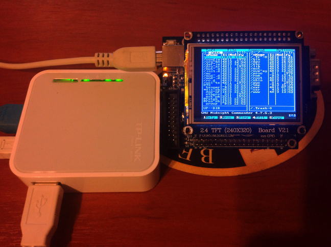
Good afternoon, dear Khabrovites. In this series of articles, we will go through a rather long, but very interesting way to turn an ordinary router into a mini-computer with an LCD display. To do this, we will first develop a USB video card based on the STM32F103 microcontroller, then a test driver that will allow us to display graphics on it, and, finally, a full framebuffer driver, thanks to which it will be possible to launch real graphics applications, such as the x-server. At the same time, we will learn to include our code in the OpenWRT source tree, finish its kernel and do other useful things.
Well, at the very end we get a result that, I hope, will cause a nostalgic tear for many readers. I will try to present the material in such a way that at the end of each stage we get a tangible result that does not allow enthusiasm to fade away. So, let's begin.
Iron
Traditionally, let's see what we need from iron. Those who do not like to solder, I can immediately reassure - all that we will do is purely hardware and software, so we don’t have to actually solder. But then you will need debugging on the STM32F103VE controller and QVGA display, which I already mentioned in my article .
We will also need, in fact, a router, which I also mentioned in another article , but we will return to it later. Now we’ll focus on developing the USB video card itself based on our debug board.
STM32F103 has two units that are very useful to us. The first one is, of course, a hardware USB controller, which is perfect for organizing the connection between our video card and host. The second is FSMC - Flexible Static Memory Controller. It is a static memory controller that can be configured to be used in conjunction with SRAM, NAND / NOR FLASH chips and similar devices, and the bus width and timings in it are configurable. In this case, the microcircuits are mapped to the address space and, when accessed to the appropriate address, the FSMC itself generates the necessary signals on the control lines and address and data buses, so for the programmer this process is completely transparent.
In the case of the display, this will help us a lot, since displays of this kind are equipped with an interface that almost coincides with the interface of the NOR flash drive and SRAM: 16-bit data bus, CS strobes, ~ WR, ~ RD. With these signals, everything is simple - CS activates the display, it starts a data exchange cycle. ~ WR or ~ RD are activated when accessing read or write, respectively.
Unfortunately, the display does not provide us with its address and data bus for direct access to video memory; instead, we have access to a single 16-bit bus and an additional RS signal, Register Select. When the RS signal is active, the value set on this bus is perceived as the address of the register (RAM cell) of the display controller, which should be addressed, and subsequent reading or writing with an inactive RS - operation with the RAM of the display.
It should be noted that RAM in this case is not video memory, it is the memory of the display controller, which is accessible from the outside through the mechanism described above. Video memory appears in the documentation as GRAM, Graphics RAM, and its contents are accessible through the "window" in the form of one of the registers. At the same time, the display controller logic itself increments / decrements the internal video memory address when sequentially reading from the same register (CTR_WRITE_DATA, CTR_READ_DATA)
FSMC does not have a specialized RS signal, so one trick is used for this: some of the available FSMC address bus signals is connected to the RS signal.
Suppose we have connected the signal A0 to RS. Then, when accessing the memory address 0x00000000 for recording (relative to the base address to which this FSMC bank is mapped), the RS signal will be inactive and the display will perceive this as setting the register address.
When accessing 0x00000001, the address line A0 will be active, and reading or writing will already be done for the RAM cell, that is, for the register whose address was specified when accessing to the zero address.
You can read more about this in the STM apnote on this issue.
A description of the registers of the display controller is available on its datasheet .
By the way, with datasheets, you should be careful and carefully look at its version, because the Chinese comrades love to first copy the chip itself (not completely, but how it will turn out), and then copy the datasheet from this chip. Therefore, in the process of reading the datasheet, you can be surprised to find registers and functions that this controller never supported and which are already wiped in the next version of the datasheet.
For example, early versions of the datasheet on this controller report that the display can do hardware bitwise operations, including a hardware mask for implementing transparency, however, if you dig deeper, it turns out that this line got into the datasheet on ILI9325 from the datasheet of another Japanese controller display, which the Chinese have safely copied and called compatible.
Since the display is already connected to the Mini-STM32, all we need to do is find out which of the chip selection signals it is connected to and which of the address lines is used as the RS signal.
According to the scheme, FSMC_NE1 is used as the CS signal, and FSMC_A16 as the RS signal.
The display also has a Reset signal output to PE1 and a backlight control signal connected to PD13.
At the same time, let's see which of the signals is used to connect the USB suspender, which we will talk about later - in this circuit it is PC13.
So, we pass to the code.
Software
LCD operation
Let's start by developing a small library for working with the display. We will work in the CooCox IDE. We will put all the addresses of the registers from the datasheet into the header file:
LCD register declaration
#define CTR_OSC_START                   0x0000
#define CTR_DRV_OUTPUT1                 0x0001
#define CTR_DRV_WAVE                    0x0002
#define CTR_ENTRY_MODE                  0x0003
#define CTR_RESIZE                      0x0004
#define CTR_DISPLAY1                    0x0007
#define CTR_DISPLAY2                    0x0008
#define CTR_DISPLAY3                    0x0009
#define CTR_DISPLAY4                    0x000A
#define CTR_RGB_INTERFACE1              0x000C
#define CTR_FRM_MARKER                  0x000D
#define CTR_RGB_INTERFACE2              0x000F
#define CTR_POWER1                      0x0010
#define CTR_POWER2                      0x0011
#define CTR_POWER3                      0x0012
#define CTR_POWER4                      0x0013
#define CTR_HORZ_ADDRESS                0x0020
#define CTR_VERT_ADDRESS                0x0021
#define CTR_WRITE_DATA                  0x0022
#define CTR_READ_DATA                   0x0022
#define CTR_POWER7                      0x0029
#define CTR_FRM_COLOR                   0x002B
#define CTR_GAMMA1                      0x0030
#define CTR_GAMMA2                      0x0031
#define CTR_GAMMA3                      0x0032
#define CTR_GAMMA4                      0x0035
#define CTR_GAMMA5                      0x0036
#define CTR_GAMMA6                      0x0037
#define CTR_GAMMA7                      0x0038
#define CTR_GAMMA8                      0x0039
#define CTR_GAMMA9                      0x003C
#define CTR_GAMMA10                     0x003D
#define CTR_HORZ_START                  0x0050
#define CTR_HORZ_END                    0x0051
#define CTR_VERT_START                  0x0052
#define CTR_VERT_END                    0x0053
#define CTR_DRV_OUTPUT2                 0x0060
#define CTR_BASE_IMAGE                  0x0061
#define CTR_VERT_SCROLL                 0x006A
#define CTR_PIMG1_POS                   0x0080
#define CTR_PIMG1_START                 0x0081
#define CTR_PIMG1_END                   0x0082
#define CTR_PIMG2_POS                   0x0083
#define CTR_PIMG2_START                 0x0084
#define CTR_PIMG2_END                   0x0085
#define CTR_PANEL_INTERFACE1    	0x0090
#define CTR_PANEL_INTERFACE2    	0x0092
#define CTR_PANEL_INTERFACE4   		0x0095
#define CTR_OTP_VCMPROGRAM              0x00A1
#define CTR_OTP_VCMSTATUS               0x00A2
#define CTR_OTP_IDKEY                   0x00A5
We remember that from a code point of view, accessing the FSMC will be a simple write / read from memory, so we need to determine which addresses to access. We look at the reference manual on STM32, the FSMC section, and we see that for NOR / SRAM addresses starting with 0x60000000 are allocated.
Banks in the broad sense in the manual mean large regions allocated for devices of various types, for example, bank # 1 is NOR / SRAM, banks # 2 and # 3 are NAND, bank # 4 is a PC Card.
In turn, bank # 1 can be used to access as many as 4 memory chips, each of which can be NOR or SRAM independently of the others. Since the display is connected as NE1, we are interested in the bank declared as FSMC_Bank1_NORSRAM1. Based on the base address, you can immediately record the definition
#define LCDRegister (*((volatile uint16_t*) 0x60000000))
The address that activates the RS will be the address where the A16 line is active, that is, for example, 0x60000000 + (2 << 16), that is, 0x60020000, so we write
#define LCDMemory (*((volatile uint16_t*) 0x60020000))
And immediately, we will determine the appropriate macros for writing values to the display registers and its memory:
#define LCD_WRITE_REGISTER(REG, DATA)	LCDRegister=REG;LCDMemory=DATA;
#define LCD_BEGIN_RAM_WRITE			LCDRegister=CTR_WRITE_DATA;
#define LCD_WRITE_RAM(DATA)			LCDMemory=DATA
At the same time, we define the names of the pins and their ports responsible for resetting the display and for turning on the backlight:
#define BacklightPin 					GPIO_Pin_13
#define BacklightPort					GPIOD
#define ResetPin 					GPIO_Pin_1
#define ResetPort					GPIOE
Now we write the initialization code for FSMC and associated peripherals:
FSMC Initialization Code
void LCDInitHardware()
{
	SysTick_Config(SystemCoreClock/1000);
	GPIO_InitTypeDef GPIO_InitStructure;
	FSMC_NORSRAMInitTypeDef  		FSMC_InitStructure;
	FSMC_NORSRAMTimingInitTypeDef  	FSMC_Timing;
	RCC_AHBPeriphClockCmd(RCC_AHBPeriph_FSMC, ENABLE);
	RCC_APB2PeriphClockCmd(RCC_APB2Periph_GPIOD | RCC_APB2Periph_GPIOE | RCC_APB2Periph_AFIO, ENABLE);
	GPIO_InitStructure.GPIO_Pin = 	GPIO_Pin_0 | GPIO_Pin_1 | GPIO_Pin_4 | GPIO_Pin_5 |
									GPIO_Pin_7 | GPIO_Pin_8 | GPIO_Pin_9 | GPIO_Pin_10|
									GPIO_Pin_11| GPIO_Pin_14| GPIO_Pin_15; //Interface
	GPIO_InitStructure.GPIO_Speed = GPIO_Speed_50MHz;
	GPIO_InitStructure.GPIO_Mode = GPIO_Mode_AF_PP;
	GPIO_Init(GPIOD, &GPIO_InitStructure);
	GPIO_InitStructure.GPIO_Pin = GPIO_Pin_7 | GPIO_Pin_8 | GPIO_Pin_9 | GPIO_Pin_10 |
	                              GPIO_Pin_11| GPIO_Pin_12| GPIO_Pin_13| GPIO_Pin_14 |
	                              GPIO_Pin_15;	//Interface
	GPIO_Init(GPIOE, &GPIO_InitStructure);
	GPIO_InitStructure.GPIO_Pin = BacklightPin;	//Backlight
	GPIO_InitStructure.GPIO_Mode = GPIO_Mode_Out_PP;
	GPIO_Init(BacklightPort, &GPIO_InitStructure);
	GPIO_InitStructure.GPIO_Pin = ResetPin; 	//Reset
	GPIO_Init(ResetPort, &GPIO_InitStructure);
	GPIO_SetBits(ResetPort,ResetPin);
	FSMC_Timing.FSMC_AddressSetupTime = 1;
	FSMC_Timing.FSMC_AddressHoldTime = 0;
	FSMC_Timing.FSMC_DataSetupTime = 5;
	FSMC_Timing.FSMC_BusTurnAroundDuration = 0;
	FSMC_Timing.FSMC_CLKDivision = 0;
	FSMC_Timing.FSMC_DataLatency = 0;
	FSMC_Timing.FSMC_AccessMode = FSMC_AccessMode_B;
	FSMC_InitStructure.FSMC_Bank = FSMC_Bank1_NORSRAM1;
	FSMC_InitStructure.FSMC_DataAddressMux = FSMC_DataAddressMux_Disable;
	FSMC_InitStructure.FSMC_MemoryType = FSMC_MemoryType_SRAM;
	FSMC_InitStructure.FSMC_MemoryDataWidth = FSMC_MemoryDataWidth_16b;
	FSMC_InitStructure.FSMC_BurstAccessMode = FSMC_BurstAccessMode_Disable;
	FSMC_InitStructure.FSMC_WaitSignalPolarity = FSMC_WaitSignalPolarity_Low;
	FSMC_InitStructure.FSMC_WrapMode = FSMC_WrapMode_Disable;
	FSMC_InitStructure.FSMC_WaitSignalActive = FSMC_WaitSignalActive_BeforeWaitState;
	FSMC_InitStructure.FSMC_WriteOperation = FSMC_WriteOperation_Enable;
	FSMC_InitStructure.FSMC_WaitSignal = FSMC_WaitSignal_Disable;
	FSMC_InitStructure.FSMC_ExtendedMode = FSMC_ExtendedMode_Disable;
	FSMC_InitStructure.FSMC_AsynchronousWait = FSMC_AsynchronousWait_Disable;
	FSMC_InitStructure.FSMC_WriteBurst = FSMC_WriteBurst_Disable;
	FSMC_InitStructure.FSMC_ReadWriteTimingStruct = &FSMC_Timing;
	FSMC_InitStructure.FSMC_WriteTimingStruct = &FSMC_Timing;
	FSMC_NORSRAMInit(&FSMC_InitStructure);
	FSMC_NORSRAMCmd(FSMC_Bank1_NORSRAM1, ENABLE);
}
Everything is quite simple here - we set the system timer for an interval of one millisecond (which will be necessary for organizing delays in the initialization of the display controller), then we configure all the signals that the FSMC owns as controlled by “alternative functions”, we configure the Reset and Backlight pins as Output Push-Pull, then go to the FSMC settings.
You can try to calculate the timing settings yourself, but I took the recommended ones from the STM apnote and they worked fine. We set the memory type as SRAM, the bus width is 16 bits, disabling all additional features, the description of which takes more than one page of the datasheet.
We declare an auxiliary function that allows us to make a fairly accurate delay:
SysTick Timer Delay Function
volatile uint32_t Tick = 0x00000000;
void SysTick_Handler()
{
	if(Tick>0)
		Tick--;
}
void SysTickDelay(uint32_t msDelay)
{
	Tick=msDelay;
	while(Tick);
}
Next, we write the initialization function of the display itself:
LCD initialization
void LCDInit()
{
LCDHardwareReset();
LCD_WRITE_REGISTER(CTR_OSC_START, 0x0001);
LCD_WRITE_REGISTER(CTR_DRV_OUTPUT1, 0x0100);
LCD_WRITE_REGISTER(CTR_DRV_WAVE, 0x0700);
LCD_WRITE_REGISTER(CTR_ENTRY_MODE, 0x1038);
LCD_WRITE_REGISTER(CTR_RESIZE, 0x0000);
LCD_WRITE_REGISTER(CTR_DISPLAY2, 0x0202);
LCD_WRITE_REGISTER(CTR_DISPLAY3, 0x0000);
LCD_WRITE_REGISTER(CTR_DISPLAY4, 0x0000);
LCD_WRITE_REGISTER(CTR_RGB_INTERFACE1, 0x0001);
LCD_WRITE_REGISTER(CTR_FRM_MARKER, 0x0000);
LCD_WRITE_REGISTER(CTR_RGB_INTERFACE2, 0x0000);
LCD_WRITE_REGISTER(CTR_POWER1, 0x0000);
LCD_WRITE_REGISTER(CTR_POWER2, 0x0007);
LCD_WRITE_REGISTER(CTR_POWER3, 0x0000);
LCD_WRITE_REGISTER(CTR_POWER4, 0x0000);
SysTickDelay(200);
LCD_WRITE_REGISTER(CTR_POWER1, 0x1590);
LCD_WRITE_REGISTER(CTR_POWER2, 0x0227);
SysTickDelay(50);
LCD_WRITE_REGISTER(CTR_POWER3, 0x009C);
SysTickDelay(50);
LCD_WRITE_REGISTER(CTR_POWER4, 0x1900);
LCD_WRITE_REGISTER(CTR_POWER7, 0x1900);
LCD_WRITE_REGISTER(CTR_FRM_COLOR, 0x000E);
SysTickDelay(50);
LCD_WRITE_REGISTER(CTR_HORZ_ADDRESS, 0x0000);
LCD_WRITE_REGISTER(CTR_VERT_ADDRESS, 0x0000);
LCD_WRITE_REGISTER(CTR_HORZ_START, 0x0000);
LCD_WRITE_REGISTER(CTR_HORZ_END, 239);
LCD_WRITE_REGISTER(CTR_VERT_START, 0x0000);
LCD_WRITE_REGISTER(CTR_VERT_END, 319);
LCD_WRITE_REGISTER(CTR_DRV_OUTPUT2, 0x2700);
LCD_WRITE_REGISTER(CTR_BASE_IMAGE, 0x0001);
LCD_WRITE_REGISTER(CTR_VERT_SCROLL, 0x0000);
GPIO_SetBits(BacklightPort,BacklightPin);
}
The sequence is taken from the datasheet to the display controller, all you need to do is simply initialize certain registers in the right order by turning on its oscillator and power, and also withstand the recommended delays, giving the display circuitry time to settle down. Also, in this code, the display modes are set, such as, for example, the behavior of the address counter when writing to GRAM - you can make the display increase or decrease the counter, move the pointers down or up - that is, set the direction in which pixels will be painted over when they are displayed in sequence .
In this code, the LCDHardwareReset function is a small block of code that sets the active level on the Reset line, waits a while, and resets it to an inactive state:
void LCDHardwareReset()
{
	GPIO_ResetBits(ResetPort,ResetPin);
	SysTickDelay(50);
	GPIO_SetBits(ResetPort,ResetPin);
	SysTickDelay(10);
}
We introduce a couple of control functions responsible for turning the display on and off at the level of its controller:
void LCDOn()
{
	 LCD_WRITE_REGISTER(CTR_DISPLAY1, 0x0133);
}
 void LCDOff()
{
	 LCD_WRITE_REGISTER(CTR_DISPLAY1, 0x0131);
}
There is very little left - we declare a very important function for us, which sets the rectangle within which the graphic will be displayed. At the same time, work with the output address lies on the shoulders of the display controller, all we need to do is set the boundaries of this area:
 void LCDSetBounds(uint16_t left, uint16_t top, uint16_t right, uint16_t bottom)
 {
    LCD_WRITE_REGISTER(CTR_VERT_START, left);
    LCD_WRITE_REGISTER(CTR_VERT_END, right);
    LCD_WRITE_REGISTER(CTR_HORZ_START, top);
    LCD_WRITE_REGISTER(CTR_HORZ_END, bottom);
    LCD_WRITE_REGISTER(CTR_HORZ_ADDRESS, top);
    LCD_WRITE_REGISTER(CTR_VERT_ADDRESS, left);
 }
It is immediately clear from the name of the registers that the function sets the left, right, upper and lower boundaries, and then sets the pointer to the position corresponding to the upper left pixel.
Since these pointers are related to the vertical position of the display, and we will use it horizontally, we should swap left and top with places, placing the left value in the registers related to VERTICAL, and top to HORIZONTAL.
And finally, the function by which we can immediately check the correct operation of the display is the cleaning function. It is a simple sequential record of the same color value in the GRAM display:
void LCDClear(uint16_t color)
 {
 	 LCDSetBounds(0,0,320-1,240-1);
 	 LCD_BEGIN_RAM_WRITE;
 	 uint32_t i;
 	 for(i=0;i<320*240;i++)
 		 LCD_WRITE_RAM(color);
 }
All we need to do to turn on our display is to execute
LCDInitHardware();
LCDInit();
LCDOn();
LCDClear(0x0000);
If everything is done correctly, the display will turn on and turn black. When replacing the argument of the LCDClear function and restarting the program, the display should be painted in the selected color.
Now let's move on to the more difficult part - USB.
USB operation
Working with USB is a very extensive and multifaceted topic, for which one article is clearly not enough.
Therefore, I recommend starting with a very useful document called USB In A Nutshell ( English version , Russian version ) before continuing.
To summarize briefly, one of the main concepts in the USB interface is Endpoint, which can be called a bit of an analogue of the socket.
Just as a socket can be opened for UDP or for a TCP connection, endpoints are also divided by type.
- Control Endpoints are used for the asynchronous transfer of small control messages, up to 64 bytes long in the case of Full Speed USB. The zero endpoint should be in any USB device and it should be Control. Through it, the host requests initial information and initializes the device. Package delivery through endpoints of this type is guaranteed; in case of an error, the host automatically tries to resend the data. Control Endpoint is the only bidirectional type of endpoints; all others work either to receive or only to transmit data.
- Interrupt Endpoints - endpoints for which host polling is important at a given frequency (we remember that USB devices cannot initiate the transfer themselves, they are waiting for a request from the host). Typically, this type of point is used in HID devices such as keyboard and mouse. The packet size can also be up to 64 bytes in FS USB. Delivery guaranteed.
- Isochronous Endpoint - an endpoint that is mainly used for transmitting audio and video information where packet loss is not terrible - in this type of endpoint only data integrity is checked, re-sending in case of an error is not performed. Packet size up to 1024 bytes in FS USB.
- Bulk Enpoints is the main type of endpoints used in information storage devices.
It assumes sending data packets with guaranteed delivery and a packet size of up to 64 bytes for FS USB (for High Speed, the packet size can reach up to 1023 bytes). The USB controller of our STM32 has the ability to organize hardware double buffering for packets of this type, increasing throughput. The entire available bandwidth remaining after Interrupt, Control and Isochronous is shared between Bulk endpoints - so you should pay attention to what other transfers go in parallel with Bulk.
The most suitable type of endpoint for our case is Bulk, we will send blocks of graphic information that will be displayed on the display, and subsequently it will be possible to organize double buffering. Moreover, we do not need any periodicity in the premises and the “streaming” nature of Isochronous endpoints, because graphic data will go in an uncompressed format to arbitrary positions of the display and lose packets to us absolutely to nothing.
In order for the host to understand what kind of device we have, what it has for endpoints and what capabilities it has, the host requests several descriptors through Control Endpoint # 0.
The structure they describe is perfectly shown in the figure from the above article:
We will return to them a little later, and now we will move on to consider what needs to be added to our firmware in order to make the device work with USB. We will work sequentially and point by point.
- First, download the STM library for working with USB from the official site and put the STM32_USB-FS-Device_Driver folder from the bowels of the downloaded archive (located in the Libraries folder) into the folder with our project. Add it to the project by selecting File - Add Linked Folder . We add a new folder to our project, calling it something like usb_user, in which we create the hw_config.h and usb_conf.h files - these files are required by the library from STM.
In hw_config.h we immediately write#include "stm32f10x.h"
otherwise there will be a bunch of errors from unresolved types (uint8_t, uint16_t, uint32_t, ...)
Do not forget to specify the folder with the library and our usb_user in the project properties as additional ways to search for inclusions. - Add a new header file to usb_user, which will contain the declarations necessary for the descriptors, let's call it, say, usb_desc.h, putting the following code there:
#include "usb_lib.h"
#define SIZ_DEVICE_DESC		0x12
#define SIZ_CONFIG_DESC		0x19
#define SIZ_STRING_LANGID	0x04
#define SIZ_STRING_VENDOR	0x10
#define SIZ_STRING_PRODUCT	0x10
#define SIZ_STRING_SERIAL	0x12
extern const uint8_t USB_ConfigDescriptor[SIZ_CONFIG_DESC];
extern ONE_DESCRIPTOR Device_Descriptor;
extern ONE_DESCRIPTOR Config_Descriptor;
extern ONE_DESCRIPTOR String_Descriptor[4];
Here, defines starting with " SIZ_ " contain the sizes of future descriptors. During the design process, these sizes are determined after the descriptors are already written, but since I already designed the device, you can just copy it.
extern const uint8_t USB_ConfigDescriptor we put in the header only because we need access to this structure from the main module. The rest of the descriptors will not be needed, because we will not give the descriptors in the form of uint_8 arrays to the library, but special structures called ONE_DESCRIPTOR , which, for such a case, are announced below. There is nothing wrong with them, it's just structures of two members, the first of which is a pointer to the same descriptor in the form uint8_t *, the second is the sixteen-bit length of this descriptor.
Now let's move on to the descriptors, adding a new usb_desc.c file and connecting our header there.
We start with a descriptor of the device itself. All the necessary information about the fields is in the article USB In A Nutshell, I’ll only note that all descriptors begin with the byte length of the descriptor (which is why we put them into defines), followed by a byte — the type of the descriptor.
This is what the device descriptor looks like:Device descriptorconst uint8_t USB_DeviceDescriptor[SIZ_DEVICE_DESC] = { 0x12, /* bLength */ 0x01, /* bDescriptorType */ 0x00, 0x02, /* bcdUSB = 2.00 */ 0xFF, /* bDeviceClass: Vendor Specific */ 0x00, /* bDeviceSubClass */ 0x00, /* bDeviceProtocol */ 0x40, /* bMaxPacketSize0 */ 0xAD, 0xDE, /* idVendor*/ 0x0D, 0xF0, /* idProduct*/ 0x00, 0x01, /* bcdDevice = 2.00 */ 1, /* Index of string descriptor describing manufacturer */ 2, /* Index of string descriptor describing product */ 3, /* Index of string descriptor describing the device's serial number */ 0x01 /* bNumConfigurations */ };
We are creating a “vendor-specific” device (not belonging to any particular predefined class like HID), with VID = 0xDEAD and PID = 0xF00D, a single configuration and a maximum packet size of 64 bytes.
Next, we declare a configuration descriptor, which includes interface and endpoint descriptors:Configuration descriptorconst uint8_t USB_ConfigDescriptor[SIZ_CONFIG_DESC] = { /*Configuration Descriptor*/ 0x09, /* bLength: Configuration Descriptor size */ 0x02, /* bDescriptorType: Configuration */ SIZ_CONFIG_DESC, /* wTotalLength:no of returned bytes */ 0x00, 0x01, /* bNumInterfaces: 1 interface */ 0x01, /* bConfigurationValue: Configuration value */ 0x00, /* iConfiguration: Index of string descriptor describing the configuration */ 0xE0, /* bmAttributes: bus powered */ 0x32, /* MaxPower 100 mA */ /*Interface Descriptor*/ 0x09, /* bLength: Interface Descriptor size */ 0x04, /* bDescriptorType: Interface */ 0x00, /* bInterfaceNumber: Number of Interface */ 0x00, /* bAlternateSetting: Alternate setting */ 0x01, /* bNumEndpoints: One endpoints used */ 0xFF, /* bInterfaceClass: Vendor Specific*/ 0x00, /* bInterfaceSubClass*/ 0x00, /* bInterfaceProtocol*/ 0x00, /* iInterface: */ /*Endpoint 1 Descriptor*/ 0x07, /* bLength: Endpoint Descriptor size */ 0x05, /* bDescriptorType: Endpoint */ 0x01, /* bEndpointAddress: (OUT1) */ 0x02, /* bmAttributes: Bulk */ 0x40, /* wMaxPacketSize: */ 0x00, 0x00 /* bInterval: */ };
Here you need to be careful - the first byte is the size of only the config descriptor itself, which is always 0x09 bytes. Next comes the type of this descriptor, but then comes the double-byte length of the entire array, including the config descriptor, descriptors for interfaces and endpoints. In this case, it fits into one byte, so the second is left zero.
Then we write that we have one interface, one configuration (located at index 0), that the device is powered by a bus and consumes no more than 100 mA.
Further in the same array there is an interface descriptor, the size of the same 0x09 bytes, two indexes, both zeros, on which the host accesses this interface specifically, the number of endpoints not counting zero - we will have one, the device class, again “Vendor Specific” , no subclasses, no protocols, no string descriptors for the interface (zeros in all corresponding bytes).
Finally, the last is the handle to our only endpoint. Endpoint 0 does not need this, so we immediately describe Bulk Endpoin 1. The address byte sets not only the endpoint number but also the direction of transmission with its high bit. We set the type to Bulk, the limit size of the packet (attention, two bytes are allocated for it!) And leave the last byte equal to zero, because it does not play a role for Bulk endpoints.
Next, declare the string descriptors:String descriptors/* USB String Descriptors */ const uint8_t USB_StringLangID[SIZ_STRING_LANGID] = { SIZ_STRING_LANGID, /* bLength */ 0x03, /* String descriptor */ 0x09, 0x04 /* LangID = 0x0409: U.S. English */ }; const uint8_t USB_StringVendor[SIZ_STRING_VENDOR] = { SIZ_STRING_VENDOR, /* Size of Vendor string */ 0x03, /* bDescriptorType*/ /* Manufacturer: "Amon-Ra" */ 'A', 0, 'm', 0, 'o', 0, 'n', 0, '-', 0, 'R', 0, 'a', 0 }; const uint8_t USB_StringProduct[SIZ_STRING_PRODUCT] = { SIZ_STRING_PRODUCT, /* bLength */ 0x03, /* bDescriptorType */ /* Product name: "USB LCD" */ 'U', 0, 'S', 0, 'B', 0, ' ', 0, 'L', 0, 'C', 0, 'D', 0 }; uint8_t USB_StringSerial[SIZ_STRING_SERIAL] = { SIZ_STRING_SERIAL, /* bLength */ 0x03, /* bDescriptorType */ 'U', 0, 'S', 0, 'B', 0, 'L', 0, 'C', 0, 'D', 0, '0', 0, '1', 0 };
Unicode strings can be changed as desired.
Finally, fill in the structures required by the library:Structures for the libraryONE_DESCRIPTOR Device_Descriptor = { (uint8_t*)USB_DeviceDescriptor, SIZ_DEVICE_DESC }; ONE_DESCRIPTOR Config_Descriptor = { (uint8_t*)USB_ConfigDescriptor, SIZ_CONFIG_DESC }; ONE_DESCRIPTOR String_Descriptor[4] = { {(uint8_t*)USB_StringLangID, SIZ_STRING_LANGID}, {(uint8_t*)USB_StringVendor, SIZ_STRING_VENDOR}, {(uint8_t*)USB_StringProduct, SIZ_STRING_PRODUCT}, {(uint8_t*)USB_StringSerial, SIZ_STRING_SERIAL} }; - Add some descriptive code to usb_conf.h:Usb_conf.h code
#define EP_NUM			0x02
#define BTABLE_ADDRESS      (0x00)
/* EP0  */
/* rx/tx buffer base address */
#define ENDP0_RXADDR        (0x40)
#define ENDP0_TXADDR        (0x80)
/* EP1  */
/* tx buffer base address */
#define ENDP1_RXADDR        (0xC0)
/* IMR_MSK */
/* mask defining which events has to be handled */
/* by the device application software */
#define IMR_MSK (CNTR_CTRM  | CNTR_RESETM)
Almost all of the above is not required by the library and is only needed to improve the readability of the code in our main module. The exception is IMR_MSK , a mask showing which USB interrupts are being used. Set it to the required minimum - interruption of Correct Transfer and Reset.
Endpoint addresses are set in the address space of the so-called PMA, Packet Memory Area, taking into account the length of the packets. Since for both endpoints the maximum packet size is set to 64 bytes, we place them with the appropriate step, not forgetting the table of these same endpoint addresses, which is stored there and also takes up space. - Now we need to define the callbacks that the library requires. These callbacks are combined into DEVICE_PROP and USER_STANDARD_REQUESTS structures , and the library will look for their instances under the names Device_Property and User_Standard_Requests .
Let's start with the callback that is called at the very very beginning, during the initialization of the USB controller, whose function is to reset the USB chunk, call the initializing functions of the library and activate the pull-up on the USB line, which makes the host see us on the bus.void Device_init ()void Device_init() { DEVICE_INFO *pInfo = &Device_Info; pInfo->Current_Configuration = 0; _SetCNTR(CNTR_FRES); //Reset USB block _SetCNTR(0); //Deassert reset signal _SetISTR(0); //Clear pending interrupts USB_SIL_Init(); GPIO_ResetBits(GPIOC, GPIO_Pin_13); //Enable pull-up }
The following callback is called when the host requests a reset of our device:void Device_Reset ()void Device_Reset() { //Set device as not configured pInformation->Current_Configuration = 0; pInformation->Current_Interface = 0; //the default Interface /* Current Feature initialization */ pInformation->Current_Feature = USB_ConfigDescriptor[7]; SetBTABLE(BTABLE_ADDRESS); /* Initialize Endpoint 0 */ SetEPType(ENDP0, EP_CONTROL); SetEPTxStatus(ENDP0, EP_TX_STALL); SetEPRxAddr(ENDP0, ENDP0_RXADDR); SetEPTxAddr(ENDP0, ENDP0_TXADDR); Clear_Status_Out(ENDP0); SetEPRxCount(ENDP0, Device_Property.MaxPacketSize); SetEPRxValid(ENDP0); SetEPType(ENDP1, EP_BULK); SetEPRxAddr(ENDP1, ENDP1_RXADDR); SetEPRxCount(ENDP1, 0x40); SetEPRxStatus(ENDP1, EP_RX_VALID); SetEPTxStatus(ENDP1, EP_TX_DIS); /* Set this device to response on default address */ SetDeviceAddress(0); }
Here we set all predefined addresses and other parameters of endpoints, and then set the device to address 0 so that the host can access it and assign a new one.
Next comes a couple of callbacks that we will not process at all#define Device_Status_In NOP_Process #define Device_Status_Out NOP_Process
Honestly, I did not even find a place where they are called, apparently, they are supposed to be called from our code, if necessary.
The following pair of callbacks is intended for the case when we want to transfer some information through Control Endpoint 0, which is not part of the standard protocol:RESULT Device_Data_Setup(uint8_t RequestNo) { return USB_UNSUPPORT; } RESULT Device_NoData_Setup(uint8_t RequestNo) { return USB_UNSUPPORT; }
Since we do not do this, in case of such an appeal, we will tell the host that we do not support this. In the future, some commands to control the backlight, power supply or display resolution can be pushed here.
Next comes the callback, which will twitch when the host wants to switch interfaces. Since we have only one interface, we say USB_UNSUPPORT when accessing any index other than zero.RESULT Device_Get_Interface_Setting(uint8_t Interface, uint8_t AlternateSetting) { if (AlternateSetting > 0) { return USB_UNSUPPORT; } else if (Interface > 0) { return USB_UNSUPPORT; } return USB_SUCCESS; }
The last three callbacks are designed to return various string descriptors and are written in the manner recommended by STM engineers by calling their library function:Functions for Returning String Descriptorsuint8_t *Device_GetDeviceDescriptor(uint16_t Length) { return Standard_GetDescriptorData(Length, &Device_Descriptor); } uint8_t *Device_GetConfigDescriptor(uint16_t Length) { return Standard_GetDescriptorData(Length, &Config_Descriptor); } uint8_t *Device_GetStringDescriptor(uint16_t Length) { uint8_t wValue0 = pInformation->USBwValue0; if (wValue0 > 4) { return NULL; } else { return Standard_GetDescriptorData(Length, &String_Descriptor[wValue0]); } }
Now we unite everything that turned out into a structure:DEVICE_PROP Device_Property = { Device_init, Device_Reset, Device_Status_In, Device_Status_Out, Device_Data_Setup, Device_NoData_Setup, Device_Get_Interface_Setting, Device_GetDeviceDescriptor, Device_GetConfigDescriptor, Device_GetStringDescriptor, 0, 0x40 /*MAX PACKET SIZE*/ }; - Now we describe the callbacks of the following structure, User_Standard_Requests .
It will be easy - because we are not HID or any other device for which there is a strict standard for such requests, we can fearlessly define them all as NOP_Process . You should not be afraid that without defining User_SetDeviceAddress we will be left without an address - this callback is informational in nature and is called by the library after the address has been set.User_Standard_Requests Structure#define Device_GetConfiguration NOP_Process #define Device_SetConfiguration NOP_Process #define Device_GetInterface NOP_Process #define Device_SetInterface NOP_Process #define Device_GetStatus NOP_Process #define Device_ClearFeature NOP_Process #define Device_SetEndPointFeature NOP_Process #define Device_SetDeviceFeature NOP_Process #define Device_SetDeviceAddress NOP_Process USER_STANDARD_REQUESTS User_Standard_Requests = { Device_GetConfiguration, Device_SetConfiguration, Device_GetInterface, Device_SetInterface, Device_GetStatus, Device_ClearFeature, Device_SetEndPointFeature, Device_SetDeviceFeature, Device_SetDeviceAddress }; - Now we will describe some global variables required by the library:
__IO uint16_t wIstr;
DEVICE Device_Table =
  {
    EP_NUM,
    1
  };
This is a global variable with current interrupt flags, and a global structure with the number of endpoints (including zero) and the number of available configurations. - Далее объявим пару вспомогательных функций – они не требуются библиотекой, мы просто вызовем их из главной:void USB_Interrupts_Config(void) и void Set_USBClock()
void USB_Interrupts_Config(void)
{
  NVIC_InitTypeDef NVIC_InitStructure;
  NVIC_PriorityGroupConfig(NVIC_PriorityGroup_1);
  NVIC_InitStructure.NVIC_IRQChannel = USB_LP_CAN1_RX0_IRQn;
  NVIC_InitStructure.NVIC_IRQChannelPreemptionPriority = 1;
  NVIC_InitStructure.NVIC_IRQChannelSubPriority = 1;
  NVIC_InitStructure.NVIC_IRQChannelCmd = ENABLE;
  NVIC_Init(&NVIC_InitStructure);
  NVIC_InitStructure.NVIC_IRQChannel = USB_HP_CAN1_TX_IRQn;
  NVIC_InitStructure.NVIC_IRQChannelPreemptionPriority = 1;
  NVIC_InitStructure.NVIC_IRQChannelSubPriority = 0;
  NVIC_InitStructure.NVIC_IRQChannelCmd = ENABLE;
  NVIC_Init(&NVIC_InitStructure);
}
void Set_USBClock()
{
  /* Select USBCLK source */
  RCC_USBCLKConfig(RCC_USBCLKSource_PLLCLK_1Div5);
  /* Enable the USB clock */
  RCC_APB1PeriphClockCmd(RCC_APB1Periph_USB, ENABLE);
}
Здесь мы конфигурируем два прерывания.
Low-Priority вызывается всеми усб событиями (успешными передачами, резетом и прочими), поэтому в нем необходимо проверять источник интеррапта.
Высокоприоритетное вызывается только при успешной передаче Isochronous либо Bulk эндпоинта с двойной буферизацией, предназначено для сокращения времени обработки (не приходится проверять источник). Так как у нас пока нет двойной буферизации, его можно не активировать.
Вторая функция устанавливает частоту тактового сигнала USB в 1.5 от системной (48 МГц) и включает тактирование блока USB. - Далее пишем код обработки высокоприоритетного и низкоприоритетного прерывания, который сводится к вызову библиотечного обработчика для высокоприоритетного и проверки источника, после чего вызова библиотечных обработчиков либо наших колбэков для низкоприоритетного.Высокоприоритетное и низкоприоритетные прерывания
void USB_HP_CAN1_TX_IRQHandler(void)
{
  CTR_HP();
}
void USB_LP_CAN1_RX0_IRQHandler(void)
{
  wIstr = _GetISTR();
	#if (IMR_MSK & ISTR_CTR)
	  if (wIstr & ISTR_CTR & wInterrupt_Mask)
	  {
	    CTR_LP();
	  }
	#endif
	#if (IMR_MSK & ISTR_RESET)
	  if (wIstr & ISTR_RESET & wInterrupt_Mask)
	  {
	    _SetISTR((uint16_t)CLR_RESET);
	    Device_Property.Reset();
	  }
	#endif
}
Все, что нам осталось сделать в меине – настроить пин подтяжки USB на выход, вызвать инициализирующие функции для USB и инициализирующие функции для LCD, после чего зависнуть в бесконечном цикле. С этого момента основная работа будет происходить в колбэке, вызываемом при передаче по Bulk Endpoint 1 данных, который мы сейчас и напишем. - Принцип работы простой – у нас будет два состояния, NOT_ADDRESSED и TRANSFER_IN_PROGRESS. Начинаем мы в первом, и в нем мы воспринимаем первые 8 байт пакета как заголовок, в котором записаны координаты X и Y (два 16-битных числа) а также количество пикселей, которое надо вывести, начиная с этих координат. Получив этот заголовок мы переходим во второе состояние и все пришедшие потом данные (включая конец первого пакета) выводим сразу на наш дисплей, пока не выведем столько пикселей, сколько указано в заголовке. Это, правда, чревато тем, что если вдруг что-то помешает передаче хотя бы одного пакета, то следующий пакет с заголовком будет воспринят как данные и на экран полетит мусор. Однако доставка гарантирована, так что подобная ситуация возможна только в случае проблем на шине. Чтобы ее избежать можно дополнительно ввести несколько байт сигнатуры в заголовок, но в моем коде этого в данный момент нет.
Единственное, что следует отметить при реализации – имеет смысл сделать свою функцию, аналогичную библиотечной PMAToUserBufferCopy, которая копирует байты из памяти буфера эндпоинта в оперативную память контроллера. Так как дисплей у нас теперь тоже видится как часть оперативной памяти, к чему нам дважды гонять туда-сюда байты?
Я взял код PMAToUserBufferCopy за основу, назвал функцию PMAToLCDBufferCopy, и просто поменял в ее коде инкрементирующийся указатель на целевой буфер на постоянный указатель на память дисплея:void PMAToLCDBufferCopy(uint16_t wPMABufAddr, uint16_t offset ,uint16_t wNBytes) { uint32_t n = (wNBytes + 1) >> 1; uint32_t i; uint32_t *pdwVal; pdwVal = (uint32_t *)(wPMABufAddr * 2 + PMAAddr+offset); for (i = n; i != 0; i--) LCD_WRITE_RAM(*pdwVal++); }
Сам колбэк выглядит так:void EP1_OUT_Callback(void) { uint16_t dataLen = GetEPRxCount(EP1_OUT & 0x7F); uint16_t offset=0; if(GraphicsState==NOT_ADDRESSED) { if(dataLen<=8) { SetEPRxStatus(ENDP1, EP_RX_VALID); return; } PMAToUserBufferCopy(buffer, GetEPRxAddr(EP1_OUT & 0x7F), 8); uint16_t horz = *((uint16_t*)(buffer)); uint16_t vert = *(uint16_t*)(buffer+2); dataTotal = *(uint32_t*)(buffer+4); LCD_WRITE_REGISTER(CTR_HORZ_ADDRESS,vert); //экран повернут LCD_WRITE_REGISTER(CTR_VERT_ADDRESS,horz); offset=16; dataTransfered=0x00; GraphicsState=TRANSFER_IN_PROGRESS; dataLen-=8; } LCD_BEGIN_RAM_WRITE; PMAToLCDBufferCopy(GetEPRxAddr(EP1_OUT & 0x7F), offset, dataLen); dataTransfered+=(dataLen)>>1; if(dataTransfered>=dataTotal) GraphicsState=NOT_ADDRESSED; SetEPRxStatus(ENDP1, EP_RX_VALID); }
Все, осталось записать колбэк в глобальную структуру, которую требует библиотека, установив колбэки от других эндпоинтов (которых у нас нет) в NOP_Process:Endpoint callback structuresvoid (*pEpInt_IN[7])(void) = { NOP_Process, NOP_Process, NOP_Process, NOP_Process, NOP_Process, NOP_Process, NOP_Process, }; void (*pEpInt_OUT[7])(void) = { EP1_OUT_Callback, NOP_Process, NOP_Process, NOP_Process, NOP_Process, NOP_Process, NOP_Process, };
Check
So the most pleasant time has come - reaping the results of the first stage.
We will carry out verification from under windows (although there will be no problems from under Linux), while using the user-specific library LibUSB.
To do this, I used its binding for C #, LibUSB.Net, which can be downloaded from here.
Connect our device to the computer - if everything is fine, the system should report that the device is working but no drivers are found, and display it under the name we set in the task manager .
In principle, you can not even write code. Just download this library, run InfWizard in the folder with it. We select our device in the list and generate an inf-file for it, after which we install the driver from libusb through it.
We start the Test_bulk that comes with the kit, select our device, click Open, and enter more than 8 characters in the line. After we press “Write”, they should come to our callback and be interpreted as a header and graphic data, after which they will appear on the display as several colored dots.
Of course, this is not very impressive, so we open the sources of this Test_Bulk itself, go to the handler of the Write button and, instead of sending data from the string, do the download from the binary file.
var bytesToWrite = File.ReadAllBytes("D:\\myfile.raw");
Here we do not need anything else, let's go prepare the file. We select a suitable image with a size of 320x240, I chose this one:

Rotate it to the side, then remember that the pixels in BMP are stored from bottom to top, so we reflect the image vertically so as not to deal with this in the code. We save in 16-bit RGB565 format.
We cut off the first 0x40 bytes (header) from the file in some hex editor, the rest is a raw bitmap that can be fed to our video card. We supplement it with the header for the USB device - the output address (0000, 0000) and the data length in pixels (320x240) - 002C0100
That's all, save it under the name that was specified in Test_bulk, run this program, click Write and get

That’s all for me. The article turned out to be long, but I did not want to break it into smaller ones, since then the integrity of the stage would be lost. I hope you have mastered it to the end and are ready to proceed to the stage that will be described in the next article - we will finally take up the router and write a small driver that allows us to work with our video card from under OpenWRT.
Until the next article!