January 21, 2013 at 16:36
Standalone radio thermometer on msp430, NRF24L01 + and solar panels
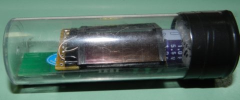
Starting exercises with a series of microcontrollers, the msp430 immediately drew attention to the scanty energy consumption in standby (low power mode) modes. I always wanted to assemble the most autonomous radio thermometer in order to nail it with nails to a tree opposite the house and to minimize the effect of heat coming out of the house on the accuracy of the readings. Battery-powered radiothermometers, even if they last for years, are also not very buzzing; climbing a tree to replace the batteries is not always great, especially in bad weather. I decided to try the solar power circuit.
The system consists of a set of sensors (in my case, an external thermometer) that send data to a central node (receiver) connected to a FreeBSD netbook that acts as a storage (and in the future, the central processor of a smart home)
Let's consider everything in order.
External sensor
Composition:
1. Microcontroller msp430g2553 with 32768Hz quartz
2. Thermometer from Maxim DS1621 Why is it? because it was.
3. The radio module on the NRF24L01
4. The 1F ionistor
5. 2 solar panels SINONAR SS-3514 (I did not find the pdf)
Electronics details:
1. The thermometer works on i2c and the radio module on SPI. Combine the signal lines of the SDA interfaces with MOSI, and SCK with MISO. (Working in turn, they will not interfere with each other. I can specify, if necessary)
2. We connect the feeding leg of the thermometer as well as the i2c pull-up resistors to one of the msp430 outputs. What for? In sleep mode, turn off the thermometer and suspenders from the power supply in general, reducing energy consumption.
3. I used a 1F ionistor as an energy storage device. I wanted to use a battery, but fashionable lithium-ion and lithium-polymer do not charge at low temperatures. NiMH is large in size, and self-discharge is large enough, which is critical for micro consumption.
4. As protection against overcharging of the ionistor, just like overvoltage, turn on 2 LEDs in parallel with the power supply. The drop on one 1.8V diode on two is 3.6V. By the way, the idea of creating a reference voltage generator on an LED was read in childhood by the Young Technician in his journal.
Here, in fact, is the external sensor circuit:

Nuances of the operation algorithm:
1. Turn on the thermometer, wait for the data to be ready, periodically putting the processor to sleep in lpm3 mode (only 32 kHz ACLK works).
2. We measure the voltage of the processor (11th channel of the ADC) relative to 2.5V of the reference voltage
3. We wake up the radio module, form an 8-byte packet containing the sensor id, status, supply voltage and temperature.
4.
5. If a drop in the supply voltage is found below the critical boundary, we wake up not every 2 minutes, but every 10 minutes.
In deep hibernation mode, and this is the main state of the system, the total current consumption is 1.5 - 1.8 μA . I didn’t drive before the shutdown, but after a day of operation the voltage on the ionistor dropped from 3.6V to 2.2V. Those. in the absence of a
Layout:


Prototype:


Structurally, the external sensor decided to place in an empty transparent jar from some kind of chemical. To prevent the formation of moisture, I put a bag of selicogel inside.
A photo of the finished device is at the beginning of the article.
Sources (in the picture archive):

Receiver
Composition:
1. The microcontroller msp430g2553
2. The radio module NRF24L01 +
3. The USB-COM converter for connecting to the server.
The circuit for connecting the NRF24L01 + to the microcontroller is the same as in the external sensor.
Algorithm: sitting at the reception. When a packet arrives, send it uart, wait for the next packet.
Brain
The intellectual part of the system is made on the remains of the Asus EEE PC. Why on the leftovers? Because there is no screen and clave. FreeBSD 9.0 is installed.
From the software:
1. lighttpd - web server
2. rrdtool - package for storing and visualizing statistical data The
daemon written in PERL listens for USB2COM converter reception, when it detects a received packet from the sensor, it adds the temperature and voltage data to the RRD database.
When connecting a browser to the web-server, we observe the current temperature value and the sensor voltage

Plans:
1. Inject radios
2. Accordingly, expand the functionality of the central node. In general, the notorious "smart" home.
Waiting for comments and questions.