Z-Wave Smart Home
For a long time I nurtured the idea of how best to make convenient control of light and electrical appliances in the apartment. At the same time, I wanted to have some kind of ready-made modular solution for a relatively simple independent setup. So, quite by accident, I came across equipment that can be implemented into the existing home network completely "painlessly". It turned out to be devices that use the Z-Wave protocol .
Z-wave
Z-waveis a patented wireless communication protocol designed for home automation, in particular for monitoring and control in residential and commercial buildings. The technology uses low-power and miniature radio frequency modules that are built into consumer electronics and various devices such as lighting, heating, access control, entertainment systems and household appliances. This is a wireless radio technology designed specifically for remote control. Unlike Wi-Fi and other IEEE 802.11 data transfer standards, designed mainly for large flows of information, Z-Wave operates in the frequency range up to 1 GHz and is optimized for the transmission of simple control commands (for example, turn on / off, change volume, brightness etc.).
Other advantages of Z-Wave include low energy consumption, low cost of production and integration of Z-Wave in various household devices.
In the world there are more than 200 manufacturers offering products with Z-Wave chips or modules. A distinctive feature of Z-Wave is that all these products are compatible with each other.
The Z-Wave solution is based on mesh mesh technology, in which each node or device can receive and transmit control signals to other network devices using intermediate neighboring nodes. Mesh is a self-organizing network with routing dependent on external factors - for example, if there is an obstacle between the two nearest network nodes, the signal will go through other network nodes that are in range.
Iron
Of the devices to choose from on the Internet, there were various control centers (gateways) in the form of completely budget USB sticks with support for different OSs:

and not very budget ones, like these:

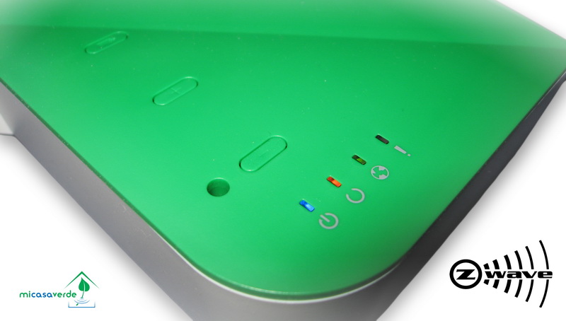
I decided not to contact the USB option for my server with FreeBSD, but stopped the choice is based on the average price and functionality of the Vera Lite gateway :

The main “for” was the availability of a convenient UI when working via the web (plugins from the market, your own scripts) and Android software when working not via the web.
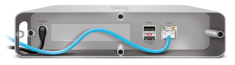
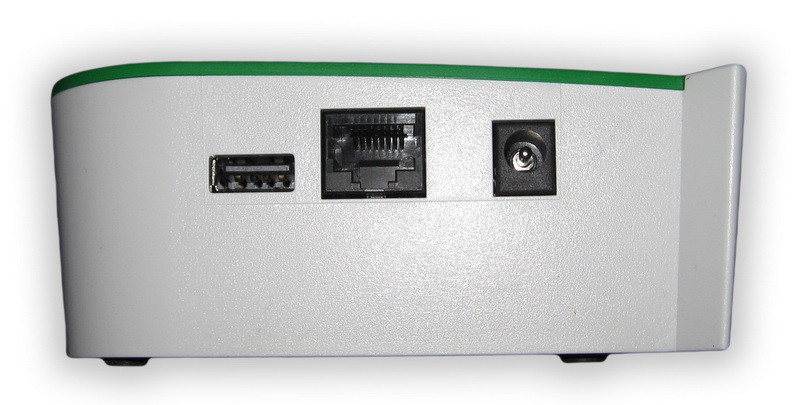
Inside the device are:
- CPU RaLink RT3662 SoC, Linux 2.6
- Parallel NAND Flash 32 MB
- RAM DDR2 64 MB
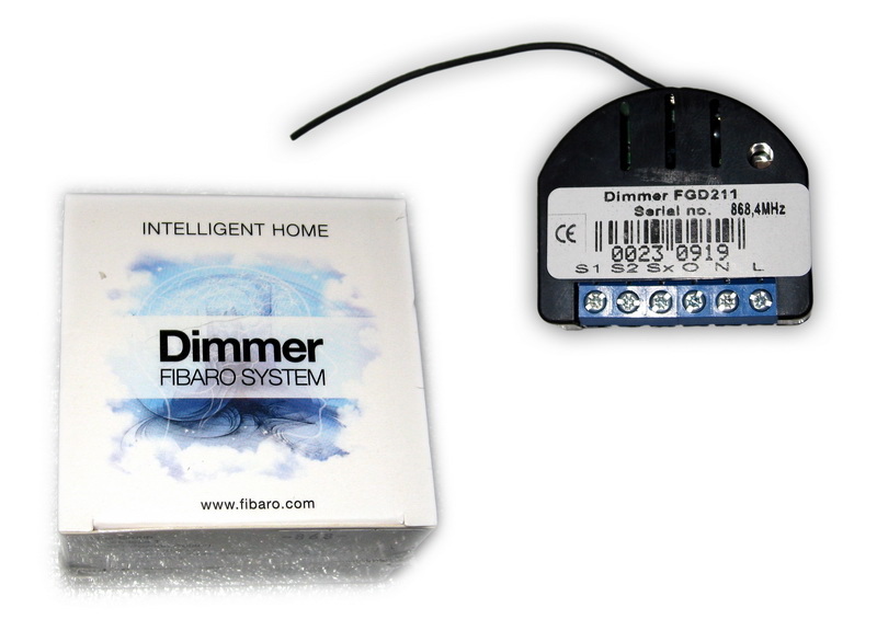
For testing, I decided to order several dimmers for adjusting the lighting of the
relay for two outputs of 1.5 kW for sockets,

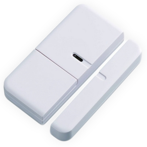
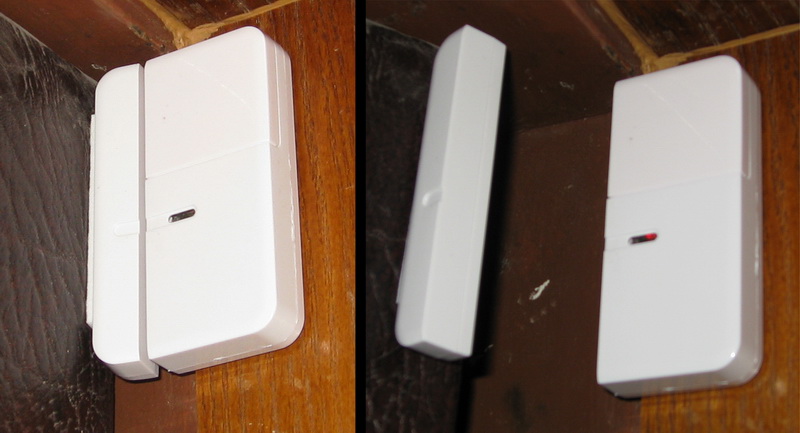
a window / door opening sensor, which I immediately installed on the front door
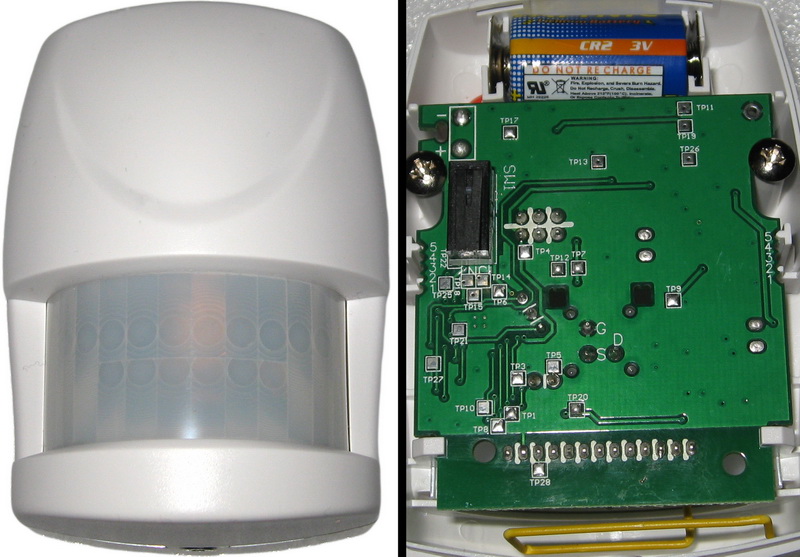
and a motion sensor in the corridor (could not resist, disassembled)

The whole set cost me ~ 20 000 rub
How it was
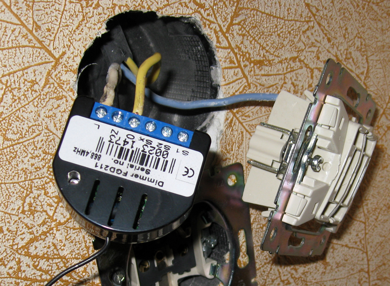
The first thing I decided to check was the remote control of the light. The main feature of this dimmer is that it only needs two wires that are suitable for the switch.

By the way, the sockets should be 50 mm or more deep, otherwise the design may not fit. But with my Legrand circuit breakers such difficulties did not arise.
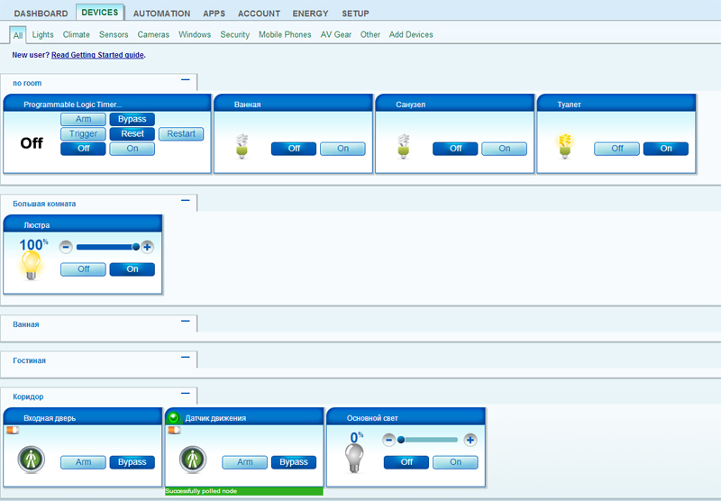
I skolkhozil this design and, having connected to the gateway from the phone, checked the work.
It is impossible to remove the dimmer immediately into the box, since it must also be tied to the gateway by pressing the “B” button three times.
The command is transmitted to the controller immediately (if there are no commands from other devices in the queue), and the status of the command execution is transmitted a little later after confirmation.
If you adjust the light from the switch, then on the phone or in the web interface, the status will immediately change.
By default, the dimmer is configured to work with the so-called bell button (with a return spring), but through the configurator in the Vera Lite web interface, following the instructions for the dimmer, you can configure the work with classic switches (in the switch mode, when each position can turn on , and turn off the light, and in the mode when up - on, down - off). I liked the default option more, as it is more convenient to adjust the brightness, and there is no need to click the keys again if the light was turned on / off by timer or remotely.
Here is some list of dimmer options available for configuration via the web interface:
- % adjustment step (Default 1)
- time to automatically reach extreme adjustment values (0 - 2.5 seconds). Simply put, during what time the chandelier will gain full brightness when turned on or vice versa.
- maximum dimmer adjustment level (2 to 99%)
- minimum dimmer adjustment level (from 1 to 98%)
- switch type switching (bell monostable button or classic bistable switch)
- double-click option (sets the brightness to 100% regardless of the previous value)
- maintaining the previous level of adjustment in case of power loss
The only problem that I did not know how to solve initially was the walk-through switches in the corridor. But the solution was extremely simple. Dimmer with bell buttons are connected in exactly the same way, i.e. on the one hand, the zero from the lamp is immediately connected to the free wire to the other switch, and on the other hand, the phase wire is connected to the same free wire to the first button. Thus, any number of buttons can be connected to the circuit.
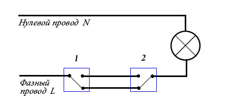
The diagram shows an option in which one of the buttons is pressed and held.
With a relay, not everything is so much fun as with a dimmer, because here neutral is already needed for operation.
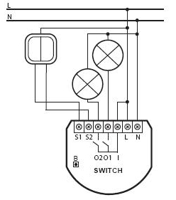
The only place where the light control is not so critical, and neutral is available, is the block of switches for the bathroom and the kitchen. Also, in order to save space in the sockets, it was decided to put two relays (1 - light in the bathroom and toilet, 2 - light in the kitchen and a socket under the switches) and two dimmers (fans in the bathroom and toilet).
At the “test” stand with overhead switches, I again skolkhozil the design for checking and setting the relay.
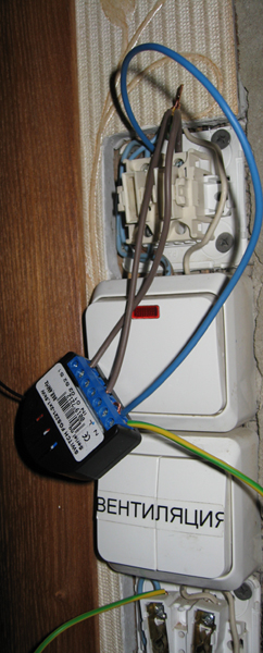
This block of switches is now in the process of remaking, so I will not say anything more about the operation of the devices there.
Scenarios
For example, I will consider the simplest scenario of turning on the light in the corridor when someone comes home.
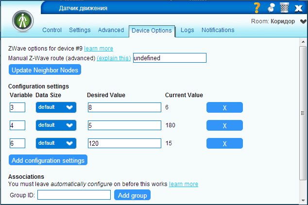
I will not consider such nuances as the behavior of various devices of the system during non-standard actions (take out the trash and open and close the door just like that) - for this purpose, the parameters of the devices used use various parameters that are set via the web interface
Note: for motion sensors and door openings there are two modes of operation: Armed and Bypass (in other words, observation and rest).
My script is extremely simple:
If the door open sensor has fired at rest, put the motion sensor in surveillance mode, and if the motion sensor has fired in surveillance mode, turn on the light and put the motion sensor into rest mode. At the same time, it is necessary to set the interval of repeated operation of the door sensor, in order to avoid disruptions to the script.
The plans are to create automation scenarios in various rooms of the apartment depending on the time of day, room temperature, brightness and attach their temperature sensors through a special module for the gateway. While all the additional equipment is in the process of delivery.