July 12, 2012 at 21:56
Learning the MIPS Assembler

According to Wikipedia , MIPS is a microprocessor developed by MIPS Computer Systems (currently MIPS Technologies) and first implemented in 1985. There are a large number of modifications of this architecture, created specifically for 3D-modeling, fast processing of floating point numbers, multi-threaded calculations. Various versions of these processors are used in Cisco and Mikrotik routers, smartphones, tablets and game consoles.
MIPS instructions are simple enough to understand, and it is from it that it is recommended to start learning assembler. What now, in fact, we will do.
Program structure in MIPS assembler
This is what the classic MIPS assembler program looks like.
Everything that starts on a point is directives . Directive
.datameans the beginning of a data segment, .text- the beginning of a code segment. All followed by a colon - a mark (
v:, main:, loop:and endloop:). All text following the sign
#is comments . And what remains is, in fact, instructions and pseudo- instructions (macros).
.data
  v: .word -1, -2, -3, -4, -5, -6, -7, -8, -9, -10
.text
.globl main
main:
  li    $t0, 0   # $t0 = 0 (variable a)
  li    $t1, 0   # $t1 = 0 (counter i)
  li    $t2, 10  # $t2 = 10 (count limit l)
loop:
  slt   $t3, $t1, $t2
  beq   $t3, $zero, endloop
  la    $t3, V
  sll   $t4, $t1, 2
  addu  $t3, $t3, $t4
  lw    $t3, 0($t3)
  addu  $t0, $t0, $t3
  addiu $t1, $t1, 1
  b     loop
endloop:
Types in MIPS Assembler
Here is a comparison table of the main types in C ++ and MIPS:

As you can see in the table, the choice of type in for a variable in MIPS is based only on the amount of memory that this variable will occupy. Please note that MIPS does not distinguish between signed and unsigned variables in this regard.
Labels (characters)
In the code above we used several tags.
Labels (they are also called symbols or labels) are used to give “names” to addresses in memory. These characters are divided into 2 large classes: data labels (addresses of global variables that are in the section
.data, in this case v:) and instruction labels (addresses of instructions in the section .text, for example main:, loop:). Data in a section is
.datausually stored in memory starting at address 0x10010000. Instructions are stored starting at address 0x00400000. Since each MIPS assembler instruction takes exactly 32 bits, the following label-address table will be true for our program: 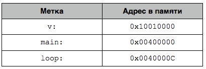
Using labels is very convenient to work with global variables and other data from
.data, But more on that later.Key Directives
Мы уже рассмотрели несколько директив, а именно
.data и .text, и уже известно, что первая предназначена для хранения данных и объявления глобальных переменных, а вторая – собственно для кода программы. Посмотрим на остальные директивы MIPS:
объявляет символ sym глобальным и позволяет обращатся к нему из других файлов;.globl sym
объявляет, что данные, которые хранятся в sym имеют размер size, и делает sym глобальной меткой (см. предыдущую директиву);.extern sym size
сохраняет строку str в памяти, не добавляя нулевой символ (\0) в конец;.ascii str
сохраняет строку str и добавляет в конец нулевой символ (\0);.asciiz str
sequentially stores bytes b1, b2, ..., bn in memory ;.byte b1, b2, ..., bn
sequentially stores in memory 16-bit values h1, h2, ..., hn ;.half h1, h2, ..., hn
sequentially stores 32-bit values w1, w2, ..., wn ;.word w1, w2, ..., wn
sequentially stores in memory 64-bit values dw1, dw2, ..., dwn ;.dword dw1, dw2, ..., dwn
stores in memory floating-point numbers f1, f2, ..., fn ;.float f1, f2, ..., fn
saves floating point numbers (double precision) d1, d2, ..., dn ;.double d1, d2, ..., dn
allocate n bytes in this data segment;.space n
align all of the following data to 2 ^ n bytes..align n
Regarding the last directive: let's say that
.datawe wrote .align 1. In this case, even if we write in memory, for example, to the address 0x10010000 some value of 1 byte in size, the next byte will be left empty, and if we want to write another byte to the memory, it will already receive the address 0x10010002. In MIPS, automatic data alignment is enabled by default, and therefore you can write a 16-bit value ( .half) only to an even memory address (0x10010000, 0x10010002, but not 0x10010003), a 32-bit value only to an address that is a multiple of 4, but 64-bit - only to the address multiple of 8.Data format in .data
Data is
.datarecorded in a fairly free manner. You just need to specify the label, data type and value. This code contains several examples of correct data recording:.data
var1: .byte 'A', 0xF3, 127, -1, '\n'
var2: .half -10, 0xffff
var3: .word 0x12345678
var4: .float 12.3, -0.1
var5: .double 1.5e-10
var6: .dword 0x1234567812345678
str1: .ascii “i love mips\n"
str2: .asciiz “zero-finished string"
array: .space 100
We’ll look at data types a bit deeper as they are used in the code.
Registers
One of the main parts of a MIPS processor is registers. The standard MIPS processor has 32 main registers and 32 more in the first coprocessor - a module that is used for floating point calculations. Each register has a size of 32 bits, respectively, a single type value is completely placed in it
int. To store a type variable, longyou must use two registers at once. Each register can be accessed by its serial name and its common name. The general is a bit more human-readable. The following registers are available:- $ zero ($ 0) - a register that always contains the value 0 and is read-only;
- $ at ($ 1) - temporary processor register;
- $ v0- $ v1 ($ 2- $ 3) - for the results returned by functions;
- $ a0- $ a3 ($ 4- $ 7) - for function arguments;
- $ t0- $ t9 ($ 8- $ 15, $ 24- $ 25) - for temporary data, you can use as you like;
- $ s0- $ s8 ($ 16- $ 23, $ 30) - for constant data, you can use it as you like;
- $ k0- $ k1 ($ 26- $ 27) - reserved for the kernel of the operating system;
- $ gp ($ 28) - pointer for global variables, practically not used;
- $ sp ($ 29) - stack pointer, its value is always equal to the top address of the stack;
- $ ra ($ 31) - the sun god the address of the instruction from which the function was called;
- $ f0 - for the results returned by functions, with a floating point;
- $ f4, $ f6, $ f8, $ f10, $ f16, $ f18 - for temporary data with floating point;
- $ f12, $ f14 - for parameters of floating point functions
MIPS Instructions
Note. From now on, we will look at the MIPS processor, its instructions and add-ons, using the wonderful MIPS simulator called MARS , which can be downloaded from here . The MIPS implementation in this simulator is fully compliant.
In the code at the beginning of the article, we have already identified all the functional parts of the program and defined the instructions and pseudo-instructions as what is not a comment, symbol (label) or directive. Pseudo-instructions are also called macros; they are transformed into one or more instructions during code execution. Here is a macro example:
la rdest, addrlui $at, hi(addr)
ori rdest, $at, lo(addr)As you can see, MIPS programs are always written with one instruction per line.
Types of instructions
There are three main types of MIPS assembler instructions:
- type R (register). Three registers are used as operands - the destination register (abbr. $ Rd), the first argument ($ rs), and the second argument ($ rt). An example of such an instruction is the addition of three registers:
In this case, the result of adding the values in $ t0 and $ t1 will be placed in $ t2.add $t2, $t0, $t1 - type I (immediate). The operands are two registers and a number. An example of type I instruction:
After execution, the result of adding $ t2 and the number 12 will be placed in the register $ t3.addi $t3, $t2, 12 - Type J (jump). The only operand is the 26-bit address where you want to go. Instruction manual
will go to the address 128 inj 128.text.
There are also instructions for coprocessors, but we will discuss them later.
Syscall instruction
syscall- one of the simplest, but at the same time one of the most significant instructions of the MIPS assembler. This is a service instruction, therefore it is considered separately from the rest. syscallused to access the operating system to perform actions that the processor itself is not able to perform. Before calling this instruction, you need to put the service code in the register $ v0 - a natural number from 1 to 12. Depending on the code, the operating system will perform one or another action. Here is a list of utility codes and the corresponding operating system actions that MARS supports: 
All input and output occurs through the MARS console.
Arithmetic instructions
So, let's look at some basic arithmetic instructions. Some abbreviations will be used:
rd- the register where the result is written, rs- the first argument, rt- the second argument. It may also occur imm16- a 16-bit integer or imm5- a 5-bit integer.
the sum of rs and rt is written to the rd register. Gently, may cause overflow.add rd, rs, rt
rd = rs - rt. You can also get an overflow.sub rd, rs, rt
almost the same as the previous instruction, but this cannot cause an overflow. For arithmetic calculations, it is preferable to use this instruction.addu rd, rs, rt
rd = rs - rt. Also without overflow, and therefore recommended for use.subu rd, rs, rt
rt = rs + 16-bit integer. Likeaddi rd, rs, imm16add, it can cause overflow.
the same, but without the possibility of overflow. Use it.addiu rd, rs, imm16
By the way, imm16 is interpreted as positive by default. For instance:
addiu $s1, $zero, 0xFFFF # $s1 = 0x0000FFFF (положительное значение)If you need to add a negative value, then you need to explicitly indicate this:
addiu $s1, $zero, -0xFFFF # $s1 = 0xFFFF0001 (негативное значение в дополнении к 2)Let's take a look at the real calculations using these instructions. Take, for example, the following code (in C ++):
int f = (g+h) - (i-j);And translate this code into MIPS instructions. First you need to calculate the value to the right of the '=' sign, and then assign it to the variable f. Suppose that the variable f will be in the register $ s0, g - in $ s1, h - in $ s2, i - in $ s3, and j - in $ s4. Here is the result:
addu $t0, $s1, $s2 # t0 = s1 + s2 = g + h
subu $t1, $s3, $s4 # t1 = s3 - s4 = i - j
subu $s0, $t0, $t1 # s0 = f = t0 - t1 = (g+h) - (i-j)
And now you can test the resulting code in MARS. Download the draft from here and open it in MARS:
java -jar Mars_4_2.jarAdd the code instead of the comment. Now you can execute it. First select Run -> Assemble:

Now uncheck Hexadecimal Values to see the decimal values in the registers, and select Run -> Go:
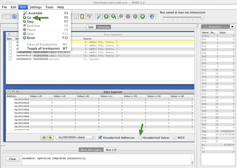
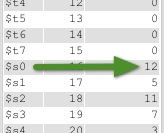
The value in $ s0 after program execution should be 12.
To be continued
In the next article, we will consider logical instructions, as well as the multiplication and division of integers. In it, we will try to work with memory and the stack. In the meantime, I suggest you try to rewrite this code here in the MIPS assembler:
int a = b + c;
int d = e + f;
int g = a + b;
int h = g + d;
Thanks for attention!