January 21, 2012 at 03:13
Simplex Sierpinski
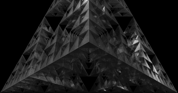
This article is intended to familiarize with the basic mathematical component of computer multidimensional graphics. Using the Sierpinski simplex as an example , the article discusses the issues of constructing, moving, projecting and displaying complex multidimensional geometric shapes.
There are also pictures, videos, sources, and I assure you that everything is very simple, read, delve into.
What is the Sierpinski triangle , and what is the Sierpinski pyramid is very clear. But what is the Sierpinski simplex? For starters, for those who haven’t read what a simplex is on a wiki, I’ll just say that a simplex is an n-dimensional tetrahedron (see video) Well, the Sierpinski simplex is a kind of fractal, built by analogy with the triangle and the Sierpinski tetrahedron.
Construction of an equilateral simplex
Do not believe it, but this is the most difficult among all that is in this article (according to my estimates). But all we need is n points in n-1 dimensional space equidistant from each other and from the center. Before reading further, I strongly recommend thinking about how you would build such points?
Of course, we are interested in cases where n> = 3, otherwise it’s just not interesting. Each nth point will be built on the basis of all the previous ones. To get started, we need to build a regular equilateral triangle:
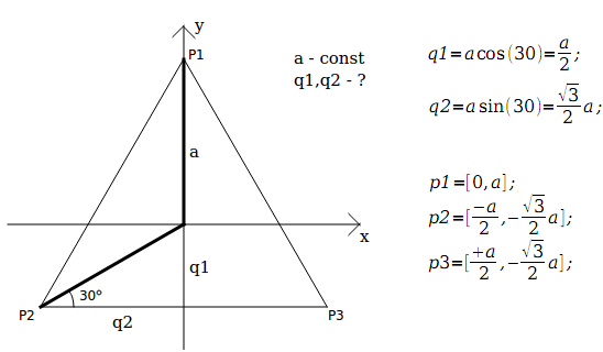
In order to add a new point, you need a new dimension (denoted by W). Introducing this measurement, so that the point is equidistant from all other points, we set q1 along the W axis for this point Pn, and -q2 to the other points along the W axis. The remaining axis coordinates for the point Pn will be left zero. What is it? That all the points that were - remain at an equal distance from each other and from the center, and the new point is equidistant from all the others. It remains only to choose such q1, q2 so that all points are equidistant from each other, and from the center.
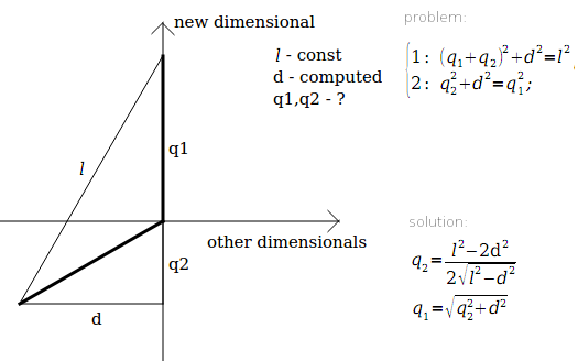
l - the distance between points - invariably, and is calculated after the construction of the triangle.
d - the distance from the points to the center - changes, and is calculated before adding a new point.
The first equation indicates that the distances from the received points to the new one should be the same.
The second is that the distances to the center should be the same.
Actually, in this way we get an equilateral simplex.
Sources:
    double c = r * sqrt(3) / 2;
    double l = c * 2;    //distance between points
    points[0][0] = + 0; points[0][1] = + r;      //first point
    points[1][0] = + c; points[1][1] = - r / 2;  //second point
    points[2][0] = - c; points[2][1] = - r / 2;  //3th point
    for (int i = 3; i <= dimensionalCount; i++)
    {
        double d =  points[0].distanceToCenter();
        double q2 = (l * l - 2 * d * d) / (2 * sqrt(l * l - d * d));
        double q1 = sqrt(d * d + q2 * q2);
        for (int k = 0; k < i; k++)
        {
            points[k][i-1] = -q2;   //set i-th dimension for all created points
            points[i][k] = 0;       //set all calculated dimension for new point
        }
        points[i][i-1] = q1;
    }
Fractalim
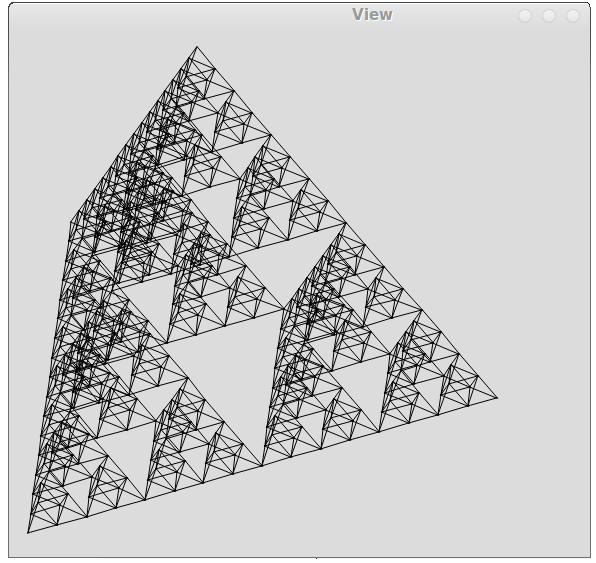
It is very easy to notice that both the triangle (n = 2) and the Sierpinski tetrahedron (n = 3) are created from the base figure by replacing the base figure with n + 1 the same, but smaller. In each of the new figures, one point of the base figure is taken as the basis, the remaining points are the centers of mass of the segments that include this point. In principle, everything is very simple and clear.
So we write:
void rec(QVector& storage, const Simplex& current, int recursionDepth)
{
    if (recursionDepth == maxRecursionDepth)
        storage.append(current);
    else
    {
        for (int i = 0; i <= n; i++)
        {
            Simplex newTriangle(current.dimensionsCount());
            for (int k = 0; k <= n; k++)
            {
                if (i == k)
                    newTriangle[k] = current[i];
                else
                    newTriangle[k] = (current[i] + current[k]) / 2.0;
            }
            rec(storage, newTriangle, recursionDepth + 1);
        }
    }
}
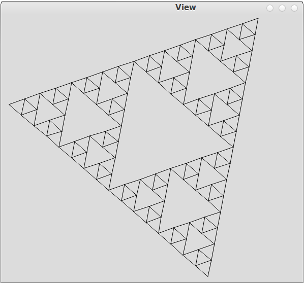
As you can see, there is nowhere else to rely on the dimension of space, and it works correctly for both 2D and 3D:
Rotate & Projection
It can be difficult to rotate (quaternions, matrix transformations), but it is possible simply ... We will do everything simply, rotate sequentially along each two coordinates. For 2D, this can be understood as a rotation around a point, for 3D - around a straight line, for ND - around a (N-2) -dimensional space. Actually, the rotation formula is calculated very simply:
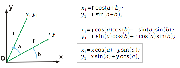
Well, it's even easier to program:
    for (int i = 0; i < coordinates.count(); i++)
        for (int k = i + 1; k < coordinates.count(); k++)
            {
                ratio = sqrt(2 + i * coordinates.count() + k);
                p1 = temp[i] * cos(angle * ratio) - temp[k] * sin(angle * ratio);
                p2 = temp[k] * cos(angle * ratio) + temp[i] * sin(angle * ratio);
                temp[i] = p1;
                temp[k] = p2;
            }
Where ratio is a coefficient so that rotation in different directions is at different speeds, preferably without loops. temp [i] - the ith coordinate of the current point.
Projection is the most difficult moment of working with multidimensional spaces. There are many reasons:
1. No one is used to understanding multidimensional geometric objects.
2. The optics of physics is silent about this (as far as I know).
3. A bunch of different methods and everyone overloads the picture, and it is not clear what is more correct.
We will take the simplest method - perspective projection. We will project an n-dimensional point onto (n-1) space ... Thus, each time lowering N, we come to the point that the point is already two-dimensional or three-dimensional and can already be displayed.
Using 2D to 1D as an example, let's try to calculate the perspective projection formula.

It can be seen that using 2 coordinates and a certain constant focus, you can make 1 coordinate. And the formula is very simple, like the code:
  for (int i = coordinates.count() - 1; i > 3; i--)
        for (int k = 0; k < i; k++)
            temp[k] *= focus  / (focus + temp[i]);
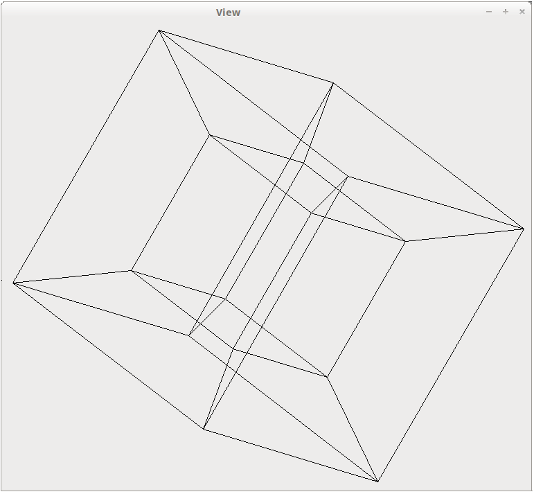
How correct is this? Generally not correct, not once, not a bit! But judging by what is on the internet, something very similar is used by other programmers. Here, for example, is a tesseract obtained by this projection method:
Rendering
QPainter is the easiest way, which is to use standard tools of the development environment to draw everything with normal lines, without lighting, filling triangles, etc. In my sources, it is turned on by default, and will work wherever Qt is (Windows, Linux, Mac OS ...).
Actually, this is how the rendering code looks:
  QPoint center(this->width() / 2, this->height() / 2);
  foreach(const Simplex& simplex, simplexes)
     for (int i = 0; i < simplex.dimensionsCount() + 1; i++)
         for (int k = i+1; k < simplex.dimensionsCount() + 1; k++)
             p.drawLine(simplex[i].to2D(focus, angle) + center, simplex[k].to2D(focus, angle) + center);
As you see, nothing is simpler ... But we need to be beautiful, right?
OpenGL , DirectX is a progressive method that allows you to render everything beautifully in real time. But there is a misfortune: nothing will be beautiful without transparency, and the transparency of these two monsters suggests that you need to render from far (z -> max) to close (z -> min). To do this, each frame, triangles need to be sorted, and in my example about 6000. Well, it doesn’t matter, the trouble is that in the general case it is impossible to determine which triangle is closer and which is farther. Moreover, when we talk about projection from multidimensional space, we say that the triangles intersect. As a result, they need to be cut and sorted each iteration, which is already very difficult ...
I did not implement this method.
Ray tracing is what the doctor ordered. This technology will allow you to get a picture of maximum quality and has a drawback only in speed. But, in fact, we do not need real time.
For tracing, I used POV-Ray , which was ideally suited for this task only because it knows how to start from the command line, without any GUI there.
To use this miracle, I wrote a certain template, which the program fills with the necessary points, and the output is a .pov file ready for tracing. A template based on a set of points builds triangles and frames, and is very simple in its structure:
#declare ppp = array[<>]
{
<>
};
#declare i = 0;
#while(i < <>)
    #if (vlength(ppp[i] - ppp[i+1])!=0)
        cylinder{ppp[i],  ppp[i+1], 0.2
            texture {pigment{color Gray}}
        }
    #end
    #if (vlength(ppp[i] - ppp[i+2])!=0)
        cylinder{ppp[i],  ppp[i+2], 0.2
            texture {pigment{color Gray}}
        }
    #end
    #if (vlength(ppp[i+1] - ppp[i+2])!=0)
        cylinder{ppp[i+1],  ppp[i+2], 0.2
            texture {pigment{color Gray}}
        }
    #end
    polygon {4
        ppp[i], ppp[i+1], ppp[i+2] ,ppp[i]
  	texture { Surface_Texture }}
#declare i=i+3;
#end
Actually, based on this template, 1000 pictures were made with different turns, from which later this video was made:
Sources The
article is dedicated to the girls of the heavy metal team Fight with Fate.