Bypass PIC Microcontroller Integrated Protection
In the comments on the recent topic about opening the processor, an article was mentioned on how to circumvent the built-in protection against reading the microcontroller firmware (the so-called Fuse-bits). I liked it, below is a translation with some additions and explanations.
I thought it would be nice to try one of those PIC microcontroller hacking techniques I've heard about. Typically, PIC microcontrollers have a certain number of so-called fuse-bits, which serve to protect against reading or modification of some parts of the memory. However, there are times when it becomes necessary to read the contents of an already programmed and protected controller (legally). A typical example is the loss by a company of technical documentation for a device, or the dismissal of those people who initially developed protected microcontroller firmware. This also happens often when a company wants to update its product line.
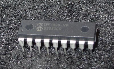
I bought four PIC18F1320 and began to torment them. This is what the PIC18F1320 looks like in its original, unbroken form:
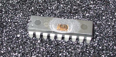
The first thing to do is to heave the upper part of the case so that the silicon interiors of the microcontroller become accessible. Although there are many amateur ways to do this, they are usually based on the use of nitric or sulfuric acid. Firstly, these are most likely not the things that you really want to see next to you. Secondly, they are not easy to get, because, for example, nitric acid is one of the components for the manufacture of explosives. I decided the easiest and most reliable way was to send the microcontrollers to a failure analysis lab like MEFAS, and for $ 50 and 2 days get on your hands already "headless" components. For this project, I deleted the compound from three microcontrollers. Two of them remained fully operational, and one completely lost its corps, i.e. only the chip remained. This was dictated by the design features of my microscope at high magnifications.
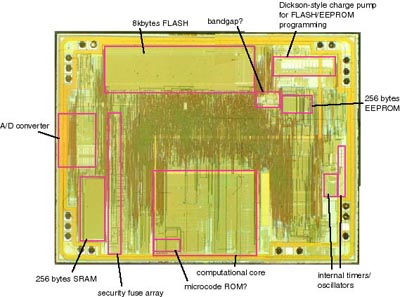
A short examination of the chip surface revealed some characteristic areas of the microcontroller shown below: Visible (clockwise): 8 KB flash-memory, voltage reference source, charge pump for programming flash / EEPROM memory, 256 bytes of EEPROM memory, built-in timers and clock circuits , computing core, ROM with microcode, array with fuse-bits, 256 bytes of RAM, ADC. (
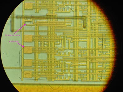
One structure immediately attracted my attention: a series of metal screens above the transistors, which were arranged in the correct order, and the number of which coincided with the number of fuse-bits. Full overlap of elements with metal screens on silicon crystals is very rare, and by itself, such elements attract attention because contain something extremely important.
Let's think a little about these metal screens. What are they needed for? First, let us recall some interesting facts about flash technology (this type of memory is also used in PIC microcontrollers for storing fuse bits). Flash technology involves the use of floating-gate transistors, very similar to those used in older IF-erase ROM chips (do you remember the 2616s in a ceramic case and with quartz glass?). In both flash and UV-ROM, data is stored by injecting electrons onto a floating gate using the tunnel effect, where these electrons can last for decades. Additional electrons in the floating gate create noticeable changes in the characteristics of the transistor. The difference lies in the fact that in flash-memory there are enough electric impulses to erase information, while in UV-ROM, in order to “drive out” electrons from a floating gate, high-energy photons are needed. For this, ultraviolet with a wavelength of approximately 250 nm is required. In order for the UV radiation not to weaken too much, quartz glasses are used (the same windows on old ROM chips).
An important conclusion that can be drawn from the above facts: flash memory can also be erased using UV radiation, because it has almost the same transistor structure as the UV-ROM device. The case of devices with flash-memory usually prevents ultraviolet radiation from reaching the crystal surface, but since our PIC microcontroller is now devoid of the plastic top of the case, we can apply UV radiation and see what comes of it.
I conducted an experiment in which I programmed a PIC controller with sequential values from 0x00 to 0xFF, and then exposed it in my eraser UV-ROM, while I was taking a shower and checking my mail.
When I removed the controller from the eraser, I found that the flash-memory was indeed erased and returned to its original state (all values are 0xFF), and that the protective fuse-bits were also deactivated. It should also be borne in mind that UV radiation also affects EEPROM memory.
It is clear that the metal plates above the protective fuse-bits just serve as protection against dropping them separately from the flash-memory of the programs. The picture illustrates the problem (and its solution) that I encountered. In order to erase the information on the transistor flash-memory, strong UV radiation must reach its floating shutter. And metal screens prevent this by effectively reflecting UV rays.

However, due to the difference between the refractive indices of light for oxide and silicon, light incident at a certain angle will be reflected from its surface. To better understand this effect, you can jump into the pool and look at the water almost at eye level. Water will have a very good reflectivity just because of the difference in the refractive indices of water and air. This is called total internal reflection.
This reflection can just be used to cause UV radiation to bounce off the metal surface of the screen and fall back onto the floating gate of the transistor. So, turning the PIC microcontroller inside the ROM eraser, I can direct enough light so that it, reflected in the transistor area of the flash memory, causes it to be erased. After several attempts, I developed a technology that seems to work quite well.
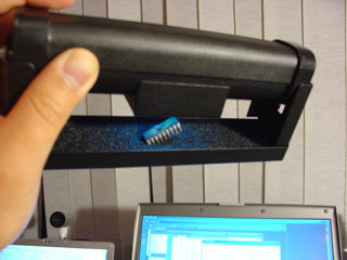
This is a photo of the microcontroller inside the ROM eraser (the blue glow around the controller is due to the UV lamp). The microcontroller is fixed at an angle in the antistatic material.
But all this cannot protect against erasing the necessary data in that part of the flash memory where the microcontroller program is stored. In order to prevent the erasure of this data, a continuous mask is used, which was very neatly cut out of the electrical tape and attached to the crystal with two tweezers, a microscope and an unwavering hand) The electrical tape effectively blocks the passage of ultraviolet radiation, thereby protecting the memory area from being erased, as well as absorbs ultraviolet reflected from the silicon substrate.
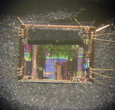
This is a photo of a crystal with an attached mask over the flash area.
Using this technique, I was finally able to reset the protective fuse bits without erasing the main microcontroller program. In the same way, you can erase only some of the flash memory. Hurrah!
Obviously, the described method is suitable only for those devices that contain reprogrammable fuse-bits. If the protection bits are programmed only once (and this happens), then this technique is not suitable. In these devices, thin conductors on a chip are simply burned. However, my colleague said that their methods of control were developed for this case as well (I think they restore contact in some similar microsurgical manner). I also know that this operation costs oh how expensive.
I would also like to note that in the popularly popular AVR microcontrollers, fuse-bits have a similar structure (they are reprogrammed in the same way), which allows us to hope that the described technique is also suitable for them!
UPD:If possible, corrected translation flaws (about the width of the forbidden zone, magnetic tape and how to fill the controller's memory).
UPD 2: the same topic, but for AVR microcontrollers, is covered here and here . Here there can be ordered the firmware to read and even buy specials. appliances.
The original article is here .
Hacking MK PIC18F1320
I thought it would be nice to try one of those PIC microcontroller hacking techniques I've heard about. Typically, PIC microcontrollers have a certain number of so-called fuse-bits, which serve to protect against reading or modification of some parts of the memory. However, there are times when it becomes necessary to read the contents of an already programmed and protected controller (legally). A typical example is the loss by a company of technical documentation for a device, or the dismissal of those people who initially developed protected microcontroller firmware. This also happens often when a company wants to update its product line.
Well, you know, there are some more situations where such skills can come in handy.
I bought four PIC18F1320 and began to torment them. This is what the PIC18F1320 looks like in its original, unbroken form:
The first thing to do is to heave the upper part of the case so that the silicon interiors of the microcontroller become accessible. Although there are many amateur ways to do this, they are usually based on the use of nitric or sulfuric acid. Firstly, these are most likely not the things that you really want to see next to you. Secondly, they are not easy to get, because, for example, nitric acid is one of the components for the manufacture of explosives. I decided the easiest and most reliable way was to send the microcontrollers to a failure analysis lab like MEFAS, and for $ 50 and 2 days get on your hands already "headless" components. For this project, I deleted the compound from three microcontrollers. Two of them remained fully operational, and one completely lost its corps, i.e. only the chip remained. This was dictated by the design features of my microscope at high magnifications.
A short examination of the chip surface revealed some characteristic areas of the microcontroller shown below: Visible (clockwise): 8 KB flash-memory, voltage reference source, charge pump for programming flash / EEPROM memory, 256 bytes of EEPROM memory, built-in timers and clock circuits , computing core, ROM with microcode, array with fuse-bits, 256 bytes of RAM, ADC. (
it would be very interesting to know how he defined all this in appearance
)One structure immediately attracted my attention: a series of metal screens above the transistors, which were arranged in the correct order, and the number of which coincided with the number of fuse-bits. Full overlap of elements with metal screens on silicon crystals is very rare, and by itself, such elements attract attention because contain something extremely important.

Let's think a little about these metal screens. What are they needed for? First, let us recall some interesting facts about flash technology (this type of memory is also used in PIC microcontrollers for storing fuse bits). Flash technology involves the use of floating-gate transistors, very similar to those used in older IF-erase ROM chips (do you remember the 2616s in a ceramic case and with quartz glass?). In both flash and UV-ROM, data is stored by injecting electrons onto a floating gate using the tunnel effect, where these electrons can last for decades. Additional electrons in the floating gate create noticeable changes in the characteristics of the transistor. The difference lies in the fact that in flash-memory there are enough electric impulses to erase information, while in UV-ROM, in order to “drive out” electrons from a floating gate, high-energy photons are needed. For this, ultraviolet with a wavelength of approximately 250 nm is required. In order for the UV radiation not to weaken too much, quartz glasses are used (the same windows on old ROM chips).
An important conclusion that can be drawn from the above facts: flash memory can also be erased using UV radiation, because it has almost the same transistor structure as the UV-ROM device. The case of devices with flash-memory usually prevents ultraviolet radiation from reaching the crystal surface, but since our PIC microcontroller is now devoid of the plastic top of the case, we can apply UV radiation and see what comes of it.
I conducted an experiment in which I programmed a PIC controller with sequential values from 0x00 to 0xFF, and then exposed it in my eraser UV-ROM, while I was taking a shower and checking my mail.
When I removed the controller from the eraser, I found that the flash-memory was indeed erased and returned to its original state (all values are 0xFF), and that the protective fuse-bits were also deactivated. It should also be borne in mind that UV radiation also affects EEPROM memory.
It is clear that the metal plates above the protective fuse-bits just serve as protection against dropping them separately from the flash-memory of the programs. The picture illustrates the problem (and its solution) that I encountered. In order to erase the information on the transistor flash-memory, strong UV radiation must reach its floating shutter. And metal screens prevent this by effectively reflecting UV rays.

However, due to the difference between the refractive indices of light for oxide and silicon, light incident at a certain angle will be reflected from its surface. To better understand this effect, you can jump into the pool and look at the water almost at eye level. Water will have a very good reflectivity just because of the difference in the refractive indices of water and air. This is called total internal reflection.
This reflection can just be used to cause UV radiation to bounce off the metal surface of the screen and fall back onto the floating gate of the transistor. So, turning the PIC microcontroller inside the ROM eraser, I can direct enough light so that it, reflected in the transistor area of the flash memory, causes it to be erased. After several attempts, I developed a technology that seems to work quite well.
This is a photo of the microcontroller inside the ROM eraser (the blue glow around the controller is due to the UV lamp). The microcontroller is fixed at an angle in the antistatic material.
But all this cannot protect against erasing the necessary data in that part of the flash memory where the microcontroller program is stored. In order to prevent the erasure of this data, a continuous mask is used, which was very neatly cut out of the electrical tape and attached to the crystal with two tweezers, a microscope and an unwavering hand) The electrical tape effectively blocks the passage of ultraviolet radiation, thereby protecting the memory area from being erased, as well as absorbs ultraviolet reflected from the silicon substrate.
This is a photo of a crystal with an attached mask over the flash area.
Using this technique, I was finally able to reset the protective fuse bits without erasing the main microcontroller program. In the same way, you can erase only some of the flash memory. Hurrah!
Remarks
Obviously, the described method is suitable only for those devices that contain reprogrammable fuse-bits. If the protection bits are programmed only once (and this happens), then this technique is not suitable. In these devices, thin conductors on a chip are simply burned. However, my colleague said that their methods of control were developed for this case as well (I think they restore contact in some similar microsurgical manner). I also know that this operation costs oh how expensive.
I would also like to note that in the popularly popular AVR microcontrollers, fuse-bits have a similar structure (they are reprogrammed in the same way), which allows us to hope that the described technique is also suitable for them!
UPD:If possible, corrected translation flaws (about the width of the forbidden zone, magnetic tape and how to fill the controller's memory).
UPD 2: the same topic, but for AVR microcontrollers, is covered here and here . Here there can be ordered the firmware to read and even buy specials. appliances.
The original article is here .