Catching the horizon with Arduino
In the comments of the post about the creation of a three-power platform based on the Arduino hardware platform, the issue of control was raised not only from the computer, so it was decided to deal with the operation of the MMA7260 accelerometer, which can be freely purchased in Hong Kong on Ebay .
To implement our plan, we will need the following components:
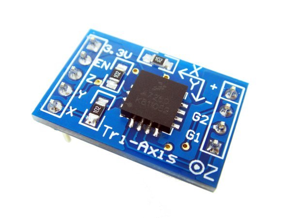
The most necessary part for our installation is an accelerometer. On the network, there are many offers for Arduino in terms of accelerometers and the most affordable is the three-axis accelerometer MMA7260. On sale, it is already supplied on the board, which already has a 3.3v 800mA stabilizer for power. Filters in the form of RC chains are soldered to the outputs of the X, Y, Z axes, and also it has a low-pass filter (which is not very noticeable at the first meeting).
In accordance with the documentation for the device, it is possible to select the sensitivity (4 modes), as well as turn on and off the sleep mode. The sensitivity setting of the sensor is carried out using inputs G1 and G2. The maximum sensitivity level is 1.5g (00), the minimum is 6g (11).
Connecting the accelerometer to the Arduino board is carried out according to the scheme presented below:
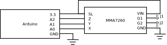
For the accelerometer to always give out values, it must be forced out of sleep mode by simply supplying power to the SL (Sleep) output. The sensitivity mode is selected using jumpers J1 and J2.
Initially, this circuit can be assembled on a breadboard, after which you can solder long wiring. Jumpers are placed on the 3x2 pad, where the leftmost two contacts are 3.3V, the center G1 and G2, respectively, and the rightmost contacts are ground.
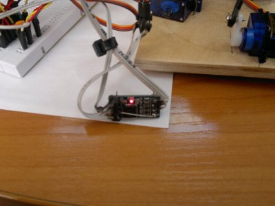
As a result, after assembly, the following construction is obtained:
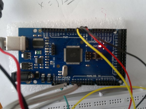
The three-stage platform is connected to the Arduino with three outputs with PWM support, and the inputs from the position sensor with three analog inputs A0 ... A2. An example of connecting nodes to an Arduino:
Testing and checking the performance of the accelerometer is carried out using the following program:
Before starting work, it is necessary to calibrate the sensor according to the following procedure:
1) Set the calibration values in the controller firmware to zero, write the firmware to the controller;
2) Fix the sensor in a horizontal position;
3) Take readings from the sensor for 3 seconds;
4) Calculate the average values in a horizontal position and adjust the calibration values.
Measurement data must be done at a minimum sensitivity or close to it in order to exclude unnecessary readings during impacts or any other effects.
Before calibration, the sensor gave the following values:
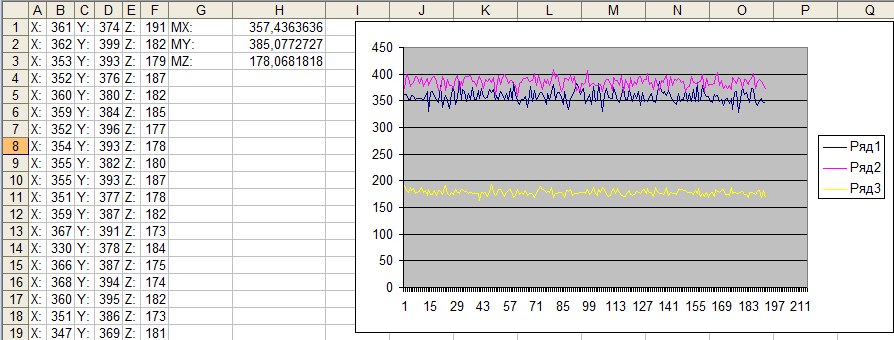
The graph shows that the withered low-pass filters work quite strange, since the axles are very noisy. To suppress noise, you must either write your own low-pass filter or normalize the measurement scale to a smaller one (in the case of servos, the noise is partially suppressed by this method).
As a result of the measurements, the following corrections were obtained:
After calibration, the sensor readings began to show the real picture:
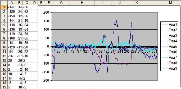
In this form, you can already use the sensor readings in your projects.
UPD. Software filtering of the signal is carried out according to the algorithm presented on Wikipedia : although I like the second option more:
Tools and materials
To implement our plan, we will need the following components:
| Naming | number |
| Accelerometer MMA7260 | 1 PC. |
| Three Power Platform | 1 PC. |
| Bread board | 1 PC. |
| Screed | 1 PC. |
| Connecting wires | 8 pcs |
| Polar bear | 1 PC. |
The most necessary part for our installation is an accelerometer. On the network, there are many offers for Arduino in terms of accelerometers and the most affordable is the three-axis accelerometer MMA7260. On sale, it is already supplied on the board, which already has a 3.3v 800mA stabilizer for power. Filters in the form of RC chains are soldered to the outputs of the X, Y, Z axes, and also it has a low-pass filter (which is not very noticeable at the first meeting).
In accordance with the documentation for the device, it is possible to select the sensitivity (4 modes), as well as turn on and off the sleep mode. The sensitivity setting of the sensor is carried out using inputs G1 and G2. The maximum sensitivity level is 1.5g (00), the minimum is 6g (11).
Wiring diagram
Connecting the accelerometer to the Arduino board is carried out according to the scheme presented below:
For the accelerometer to always give out values, it must be forced out of sleep mode by simply supplying power to the SL (Sleep) output. The sensitivity mode is selected using jumpers J1 and J2.
Initially, this circuit can be assembled on a breadboard, after which you can solder long wiring. Jumpers are placed on the 3x2 pad, where the leftmost two contacts are 3.3V, the center G1 and G2, respectively, and the rightmost contacts are ground.
As a result, after assembly, the following construction is obtained:
The three-stage platform is connected to the Arduino with three outputs with PWM support, and the inputs from the position sensor with three analog inputs A0 ... A2. An example of connecting nodes to an Arduino:
Programming
Testing and checking the performance of the accelerometer is carried out using the following program:
- int x, y, z;
-
- // Калибровка датчика
- int dx=357;
- int dy=385;
- int dz=178;
- void setup()
- {
- Serial.begin(9600);
- }
-
- void loop()
- {
- // Значения осей с датчика
- x = analogRead(A0) - dx;
- y = analogRead(A1) - dy;
- z = analogRead(A2) - dz;
-
- // Вывод в Serial monitor
- Serial.print("X: ");
- Serial.print(x);
- Serial.print("Y:");
- Serial.print(y);
- Serial.print("Z:");
- Serial.println(z);
-
- //Период опроса
- delay(100);
- }
* This source code was highlighted with Source Code Highlighter.
Testing
Before starting work, it is necessary to calibrate the sensor according to the following procedure:
1) Set the calibration values in the controller firmware to zero, write the firmware to the controller;
2) Fix the sensor in a horizontal position;
3) Take readings from the sensor for 3 seconds;
4) Calculate the average values in a horizontal position and adjust the calibration values.
Measurement data must be done at a minimum sensitivity or close to it in order to exclude unnecessary readings during impacts or any other effects.
Before calibration, the sensor gave the following values:
The graph shows that the withered low-pass filters work quite strange, since the axles are very noisy. To suppress noise, you must either write your own low-pass filter or normalize the measurement scale to a smaller one (in the case of servos, the noise is partially suppressed by this method).
As a result of the measurements, the following corrections were obtained:
- dx = 357
- dy = 385
- dz = 178
After calibration, the sensor readings began to show the real picture:
In this form, you can already use the sensor readings in your projects.
Result
UPD. Software filtering of the signal is carried out according to the algorithm presented on Wikipedia : although I like the second option more:
 function lowpass(real[0..n] x, real dt, real RC)

  var real[0..n] y

  var real α := dt / (RC + dt)

  y[0] := x[0]

  for i from 1 to n

    y[i] := α * x[i] + (1-α) * y[i-1]

  return y


* This source code was highlighted with Source Code Highlighter.
  for i from 1 to n

    y[i] := y[i-1] + α * (x[i] - y[i-1])


* This source code was highlighted with Source Code Highlighter.