VHDL for beginners. Brainfuck
As you know, VHDL is a high-level hardware description language (if in doubt, you can see it here and here ). Of the variety of tasks, I liked brainfuck because of its ease of implementation on the one hand and the magic of creating a programmable (albeit very limited) calculator on the other.
In the framework of this article, I will not delve into the jungle of syntax and environment settings, concentrating on the implementation of a specific task.
The test bench will be the Altera Cyclone II Starter Kit (EP2C20F484C7)
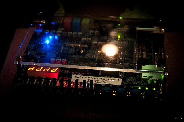
I ask lovers of flashing lights under cat.

The behavior model is set simply:
We proceed directly to the interpreter.

As you can see, you need access to the toggle switches SW, KEY buttons, LEDs and seven-segment HEX. A synchronization signal will be generated by an internal 50Mhz generator.
RUN - the same mode switch SW9, RESET - button KEY3.
Since the indicators need to show not only the output of the program, but also the contents of each specific memory cell, two vectors are used: out_result contains the output of the program, and final_out_result is connected to the decoders of seven-segment indicators.
According to the reset signal (the buttons in Cyclone II are inverse, therefore the condition is inverse), the values of the memory cells and the output vector are reset, and if the program is still being recorded, we fill in the corresponding command memory.
In any case, upon exiting the execution mode, it is necessary to “forget” about the previous results so that each subsequent start occurs from scratch.
Select output: either the program output or the value from the current cell is sent to the decoders. The selection is made using the switch SW5.
A program on Brainfuck is presented as an automaton: there is a set of fixed states, the movement between which is carried out (with the exception of cycles) linearly. Such a model on VHDL (and not only) is implemented by the switch-case construction.
As already mentioned, u is a counter of open brackets. Commands are executed only at (u = 0), in other cases, a pair bracket is searched. In normal mode and when searching for a closing bracket, the command pointer moves forward, otherwise backward. It is clearly seen here that if u were a signal, during the first reaction to the closing bracket, the command counter would increase, only at the next measure the pointer would go back, stumbled on the closing bracket a second time (u = -2), and so many paired opening brackets no - the program would never be executed.
The condition (u / = 0) is made for the implementation of nested loops.

but before flashing the device you need to test the algorithm for adequacy. I will not give the text of the testbench, it is in the attached files. I only note that a stupid sequential run of all values will not work here, therefore, the correctness of the execution of a specific program is checked. I used the addition of two numbers:
ModelSim-Altera was used as the modeling environment.


In the framework of this article, I will not delve into the jungle of syntax and environment settings, concentrating on the implementation of a specific task.
The test bench will be the Altera Cyclone II Starter Kit (EP2C20F484C7)
I ask lovers of flashing lights under cat.
Technical task
- Command memory - 64 commands, memory cells - 32 cells of 8 bits each;
- The device must support two modes: entering the program and execution; change of mode should be carried out using switch SW9;
- In the program entry mode, switches SW8 - SW3 determine the address in the program memory, SW2 - SW0 - command code; recording to memory is carried out by pressing the KEY3 button; the contents of the current memory cell is displayed on LEDR2 - LEDR0;
- In the program execution mode, the values of the memory cells should be displayed on the seven-segment indicators HEX1 - HEX0; the address of the displayed cell must be set using the switches SW4 - SW0;
- In any operating mode, by pressing the KEY3 button, the values of all memory cells must be reset.
Front marking
The project in Quartus II was created, it's time to decide on a set of entity. I decided not to stand out and, even if it’s not very beautiful, to realize everything in one essence. To output to seven-segment indicators, you need a special decoder, which we select in a separate entity.Implementation
The decoder can be implemented immediately, "on the forehead." It performs the simplest table-specific conversion, so there are only two ports:entity dc7x is
port(
i: in std_logic_vector(3 downto 0);
z: out std_logic_vector(6 downto 0)
);
end dc7x;
The behavior model is set simply:
with i select
		z <= "1000000" when "0000", --0
			  "1111001" when "0001", --1
			  "0100100" when "0010", --2
			  "0110000" when "0011", --3
			  "0011001" when "0100",
			   ********
			  "0001110" when "1111", --F
			  "0111111" when others;
We proceed directly to the interpreter.
Ports
The involved external input and output devices are shown in the figure:As you can see, you need access to the toggle switches SW, KEY buttons, LEDs and seven-segment HEX. A synchronization signal will be generated by an internal 50Mhz generator.
entity brainfuck is
	port(
		RUN: in std_logic;
		SW: 	in std_logic_vector(8 downto 0);
		LED:	out std_logic_vector(2 downto 0);
		HEX1:	out std_logic_vector(6 downto 0);
		HEX2:	out std_logic_vector(6 downto 0);
		clk: in std_logic;
		RESET: in boolean
		);
end brainfuck;
RUN - the same mode switch SW9, RESET - button KEY3.
Architecture
We will need several internal elements: arrays of command and data memory, as well as pointers to specific cells in them.Since the indicators need to show not only the output of the program, but also the contents of each specific memory cell, two vectors are used: out_result contains the output of the program, and final_out_result is connected to the decoders of seven-segment indicators.
type 		t_memory is array (31 downto 0) of std_logic_vector (7 downto 0); -- command memory
signal 	cell_memory: t_memory := (others => x"00");
type		d_memory is array (63 downto 0) of std_logic_vector (2 downto 0); -- cells memory
signal 	comm_memory: d_memory := (others => "000");
signal comm_number: std_logic_vector(6 downto 0) := (others => '0');
signal cell_number: std_logic_vector(5 downto 0) := (others => '0');
signal out_result: std_logic_vector(7 downto 0) := (others => '0');
signal final_out_result: std_logic_vector(7 downto 0) := (others => '0');
Process (clk, RESET)
Finally we got to the most important thing - the interpreter's behavior model. First, declare a counter variable for open parentheses.variable u: integer := 0; begin
if rising_edge(clk) then
if (not RESET) then
cell_memory <= (others => x"00");
out_result <= (others => '0');
final_out_result <= cell_memory(conv_integer(unsigned(cell_number)));
if (RUN = '0') then -- writing a programm
comm_memory(conv_integer(unsigned(SW(8 downto 3)))) <= SW(2 downto 0);
end if;According to the reset signal (the buttons in Cyclone II are inverse, therefore the condition is inverse), the values of the memory cells and the output vector are reset, and if the program is still being recorded, we fill in the corresponding command memory.
else
			if (RUN = '0') then
				running_led <= false;
				LED <= comm_memory(conv_integer(unsigned(SW(8 downto 3))));
				comm_number <= (others => '0');
				cell_number <= (others => '0');
				cell_memory <= (others => x"00");
In any case, upon exiting the execution mode, it is necessary to “forget” about the previous results so that each subsequent start occurs from scratch.
else -- executing
			running_led <= true;
			LED <= (others => '0');
				if (SW(5) = '1') then final_out_result <= cell_memory(conv_integer(unsigned(SW(4 downto 0)))); -- out: user's or programm's cell
					else final_out_result <= out_result;
				end if;
Select output: either the program output or the value from the current cell is sent to the decoders. The selection is made using the switch SW5.
			case comm_memory(conv_integer(unsigned(comm_number))) is
				when "000" => 			-- next
					if (u = 0) then cell_number <= cell_number + 1;
						end if;
					if (u < 0 )then comm_number <= comm_number - 1;
						else comm_number <= comm_number + 1;
					end if;
				****************
				when "100" => 			-- [
					if ((cell_memory(conv_integer(unsigned(cell_number))) = x"00") or (u /= 0)) then
						u := u + 1;
					end if;
					if (u < 0 )then comm_number <= comm_number - 1;
						else comm_number <= comm_number + 1;
					end if;
				when "101" =>			 -- ]
					if ((cell_memory(conv_integer(unsigned(cell_number))) /= x"00") or (u /= 0)) then
						u := u - 1;
					end if;
					if (u < 0 )then comm_number <= comm_number - 1;
						else comm_number <= comm_number + 1;
					end if;
			when others =>			-- stop
				if (u = 0) then
					null;
				end if;
A program on Brainfuck is presented as an automaton: there is a set of fixed states, the movement between which is carried out (with the exception of cycles) linearly. Such a model on VHDL (and not only) is implemented by the switch-case construction.
As already mentioned, u is a counter of open brackets. Commands are executed only at (u = 0), in other cases, a pair bracket is searched. In normal mode and when searching for a closing bracket, the command pointer moves forward, otherwise backward. It is clearly seen here that if u were a signal, during the first reaction to the closing bracket, the command counter would increase, only at the next measure the pointer would go back, stumbled on the closing bracket a second time (u = -2), and so many paired opening brackets no - the program would never be executed.
The condition (u / = 0) is made for the implementation of nested loops.
Testbench
The code is ready and compiled,but before flashing the device you need to test the algorithm for adequacy. I will not give the text of the testbench, it is in the attached files. I only note that a stupid sequential run of all values will not work here, therefore, the correctness of the execution of a specific program is checked. I used the addition of two numbers:
+++>++<[->+<]>.xModelSim-Altera was used as the modeling environment.
PCB layout
The last step before the firmware is to set the correspondence of the model signals to the real ports of the board. The coordinates of the conclusions are in the application “Documentation Cyclone II”, but for whom laziness is - here is the finished pinout:Conclusion
Well that's all, it remains only to open the Programmer, flash the board, and ... sit in driving all the commands and addresses manually :) I didn’t give all the code, omitting the standard parts like the use section . Promised:- Completely ready for firmware (compiled and wired on board) project
- Documentation for Altera Cyclone II (with the designation of all ports on the grid)