High-speed photography at home

about the project
I am passionate about photography. I also like to collect all kinds of electronic stuff. Probably because of this, I felt that I simply had to try to take a high-speed photograph. Edward Maybridge dabbled in such a photograph back in the century before last. In this post I will talk about the basics of high-speed photography and how I collected my photo trigger.
Introduction
High-speed photography is an extremely fast shutter speed photo that takes less than a millisecond. The principle of operation is simple: a sledgehammer, a camera, a flash, a trigger and an object are placed in a room. In absolute darkness, the camera shutter is opened, a sledgehammer is fired at the object, the trigger responds to noise and turns on the flash. A fraction of a millisecond flash illuminates the flying shards of an object. After that, the shutter of the camera is closed. The sensor remains a picture of flying shards.
I want to talk about how to assemble such a thing at home.
Assembly
Formulation of the problem
I wanted the trigger to work with different sensors. I decided to start with an audio sensor and a laser beam. With audio, everything is clear: if a sufficiently loud sound is noticed, then you need to turn on the flash. The laser sensor is almost the same as in the movie: the laser is aimed at the photosensitive element. If the beam crosses something, then you need to turn on the flash. I wanted to be able to adjust the sensitivity of the sensor and the flash delay.
Component Selection
- ATmega 328P with Arduino on board, frequency 16Mhz. I like this chip for its simplicity.
- Vivitar 283 flash . Old, Japanese, for 30 dollars. The biggest advantage of this device is that, firstly, it is difficult, and, secondly, it’s not a pity to break it. The minus of the device is that the voltage at the contacts is 380 volts. It hurts to touch a finger.
- Gate TS1220 and optocoupler MOC3010M . These two devices allowed the circuit to withstand voltages up to 600 volts.
- Microphone from Sparkfun .
- Laser pointer purchased at a nearby store and GL5528 photoresistor .
- Any infrastructure trifle: toggle switches, potentiometers and a battery with a MAX1555 charger .
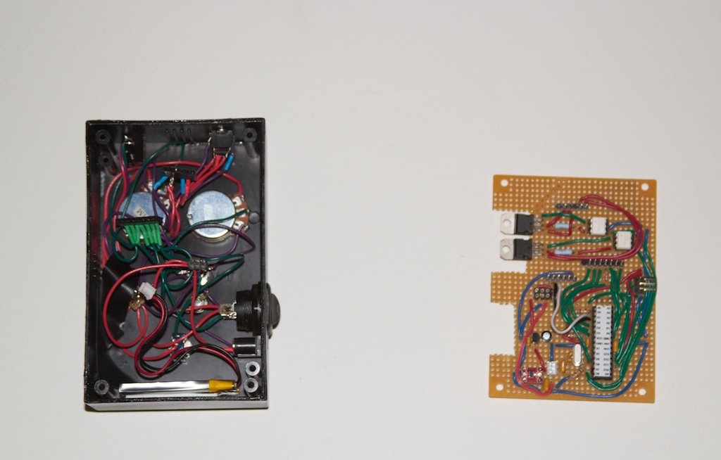
Here's what my desk looked like after building the prototype:

The laser iron method will remain on the next project. So far, everything was soldered to a regular board with holes:
The code
The microcontroller program turned out to be very simple. The most interesting thing was to make the main loop as fast as possible. For the first time in my life, optimizing the code was very real: for a couple of milliseconds, I gaped, and the most interesting event was skipped.
Sources can be found on google code .
Body assembly
I really wanted the project to have a decent building. I bought a few cheap boxes and started drawing. First I laid out what the user interface would look like:

After that, he took up the drill:

After that I took a dye for plastic VHT SP950 and painted the body. I really wanted to get rid of the type of cheap plastic. Three days of drying and the details could be returned to the house:

The matter remains for small. It was necessary to stick labels to the controls. I discovered a great tool - decals. You print signatures on special paper, dip the paper into water and transfer it directly to plastic.

Here is the result:

Result
The first results were not very satisfactory. The trigger worked as it should, but the object turned out to be blurry. And for the laser sensor:
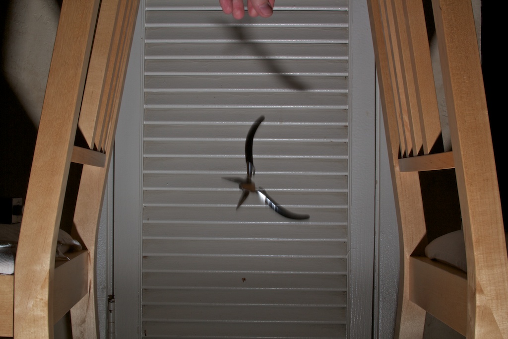
And for the audio sensor:
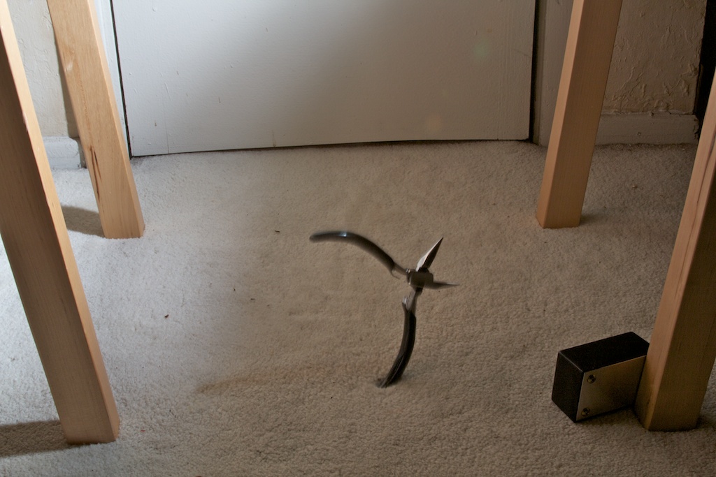
The point was in the power of the flash: an overly powerful flash turned on quickly, but rather slowly died out. A simple setup reduced power and photos became clear.
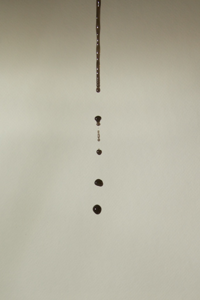
Here is a flying drop of water:
But the coffee beans land in a cup:
Conclusion
I really enjoyed working with the AVR microcontroller, high-speed photography and “iron” user interfaces.
However, now I can’t imagine what to photograph. Suggestions (as well as questions and comments) are very, very, very welcome.