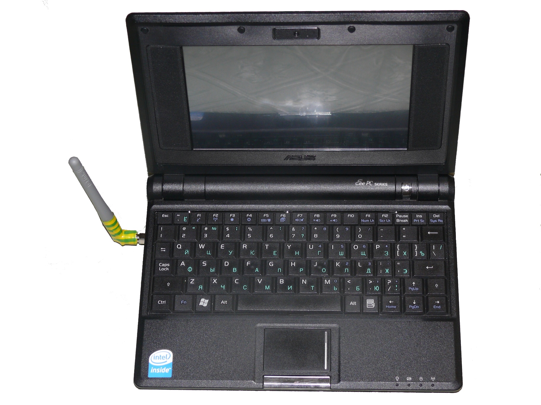
Asus Eee PC 701 4G + TouchScreen, SD, Bluetooth, 3G, Battery Switch
This Asus netbook model is famous for its number of alterations and upgrades. It is used in cars, in smart homes, it is made from simple servers, tablets, etc.
The topic may already be somewhat outdated, since this model appeared back in 2007, but nevertheless it remains the cheapest (with the exception of 2G, which few people buy) and the lightest in the Eee PC series. The main disadvantages of older models are the small size of the SSD, short battery life and low screen resolution.
I wanted from my “hedgehog” the ability to connect a GPS receiver (bluetooth), the ability to abandon the small and uncomfortable touchpad (touchscreen), more space for programs and data (SD reader), the ability to access the Internet via mobile communications (3G modem) and fixes a bug when the battery runs out quickly in a turned off netbook.
The following is a description of the operations performed on the hedgehog.
Most of the pictures are clickable.
Training
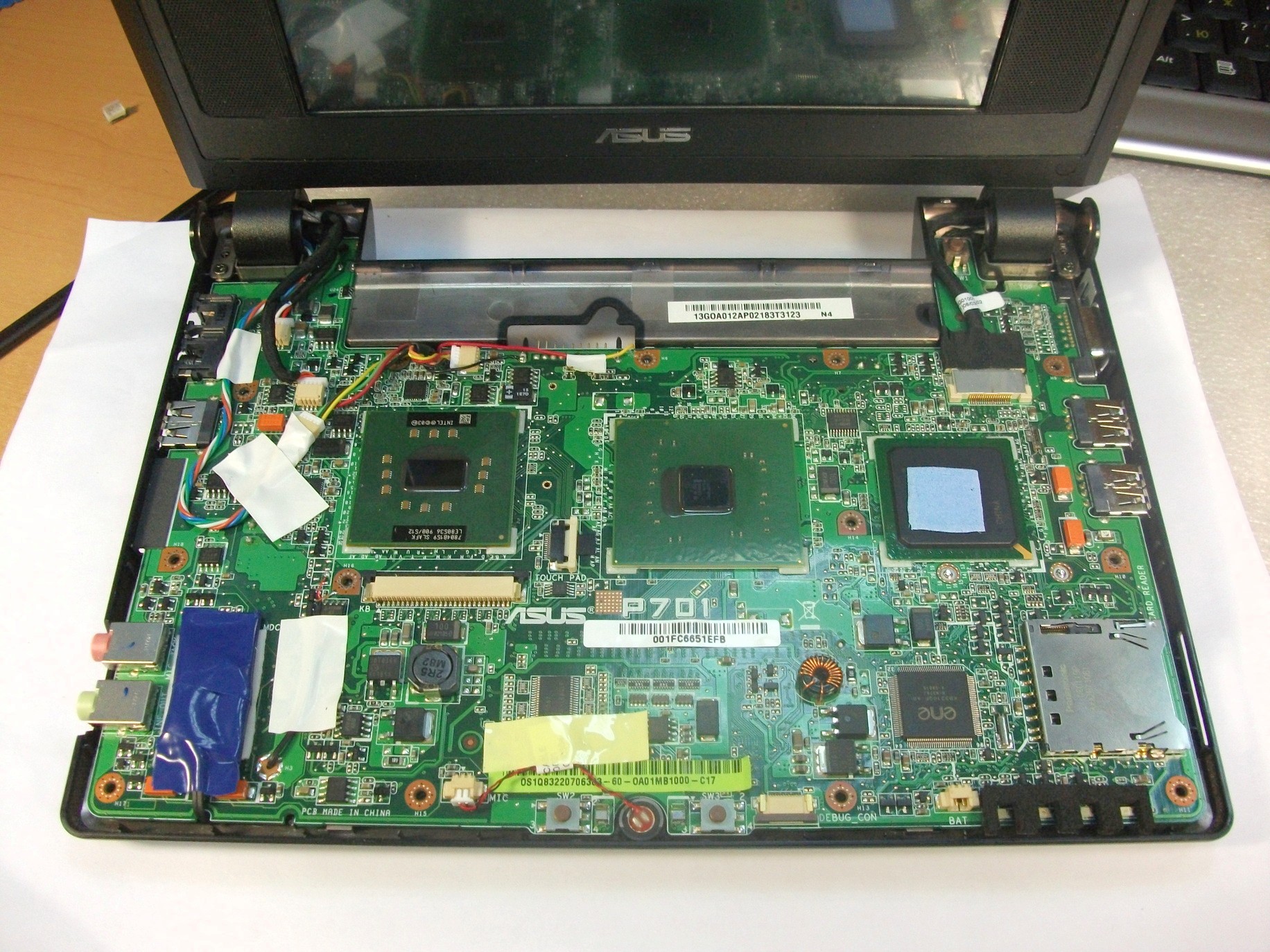
First of all, I bought all the necessary spare parts, choosing the smallest ones. Then he disassembled the Eee PC, examined its insides, found the locations of the new modules and proceeded directly to modding.
I disassembled the purchased USB hub, SD reader, 3G modem (Huawei E1550, MTS) and the bluetooth module, unsoldered the USB connectors from them and sawed off the empty parts of the boards. In addition to this, the 3G modem also untied MTS.
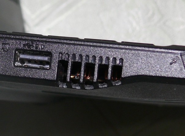
Ventilation
He started with a simple one - increased the slots in the ventilation grill. This allows you to work more efficiently with an already weak netbook cooling system. Nippers and file did their job.
Touchscreen
Then I installed the touchscreen. I bought what I could, he cost me somewhere in 1300 rubles, I don’t remember exactly. eGalaxy resistive, 7 inch with USB interface. To my surprise, in Kubuntu 10.04 it worked right away.
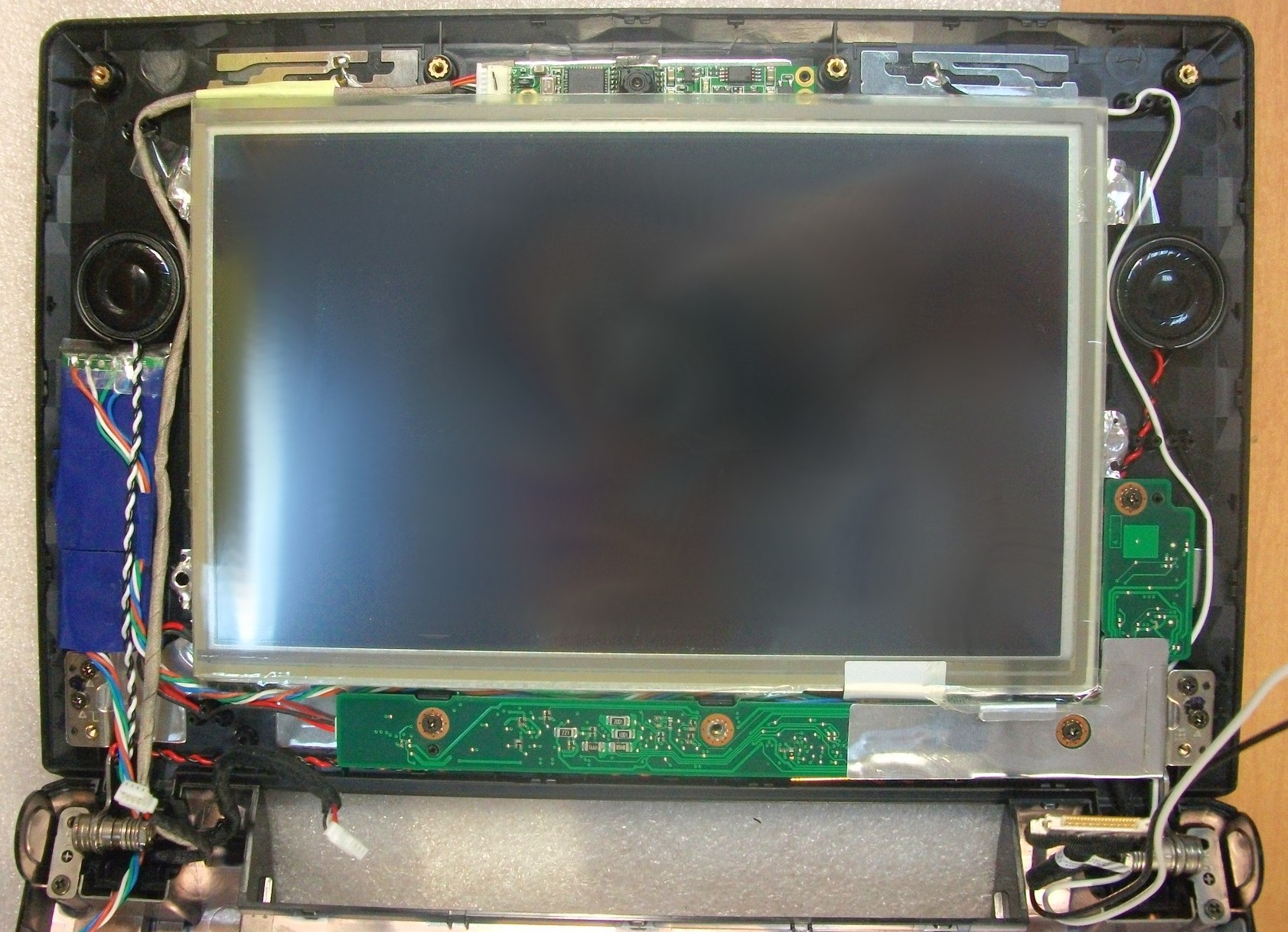
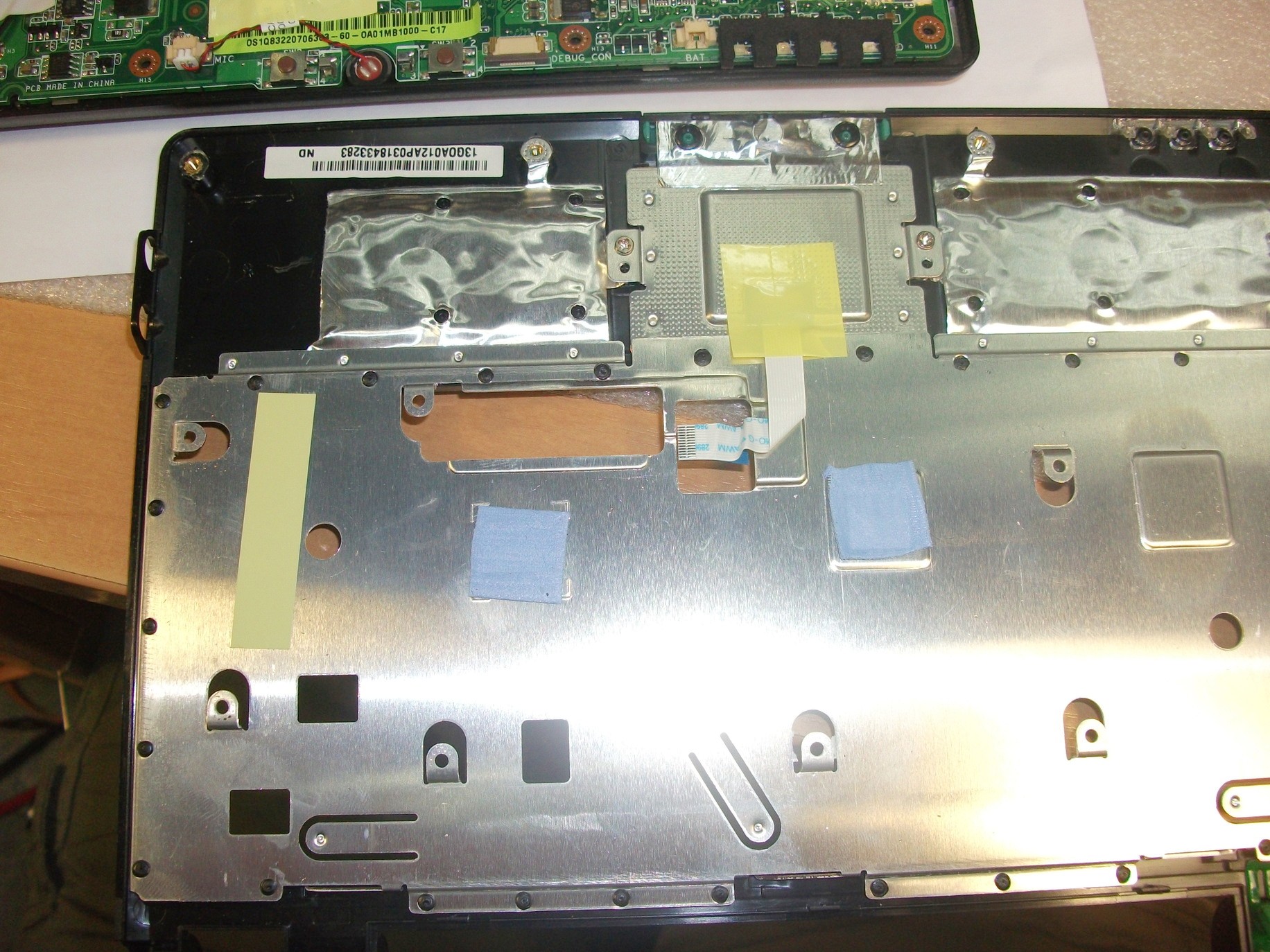
I placed the touchscreen controller on the left under the speaker. The cable from the screen itself exits from the lower right part of it, there, under the motherboard of the hedgehog's native screen, I soldered the wires to the cable and sent them to the controller. Under the native screen, I previously removed the foil, saving maybe a millimeter. After assembling the case, the plastic began to protrude a little, but this is almost not noticeable. Other modders still remove the matte coating from the screen to make it brighter, but I left this coating, I love it when the screen is matte, and such strong glare does not appear in the sun.
It was difficult to put a touchscreen so as not to leave specks of dust under it. Compressed air helped well in this matter.
Battery
To eliminate battery leakage, one of its contacts must be broken and connected to the ground only when you need to turn on the netbook. The network has a tip to collect the key on the transistor, which would automatically close when the Eee PC is turned off, and to turn it on you need to open it using the usually right button on the touchpad. It seemed to me too unreliable and uncomfortable. I implemented this business using the world switch and battery lock.
First, I gently torn the desired contact, unsoldering from the board:
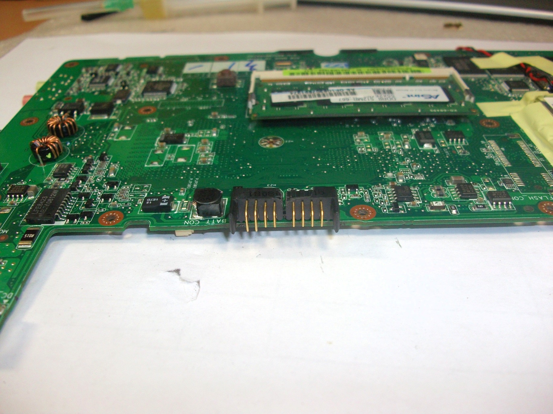
Then inserted back, but with wires that go to the switch.

Here I stuck a micro switch next to the battery latch on superglue:
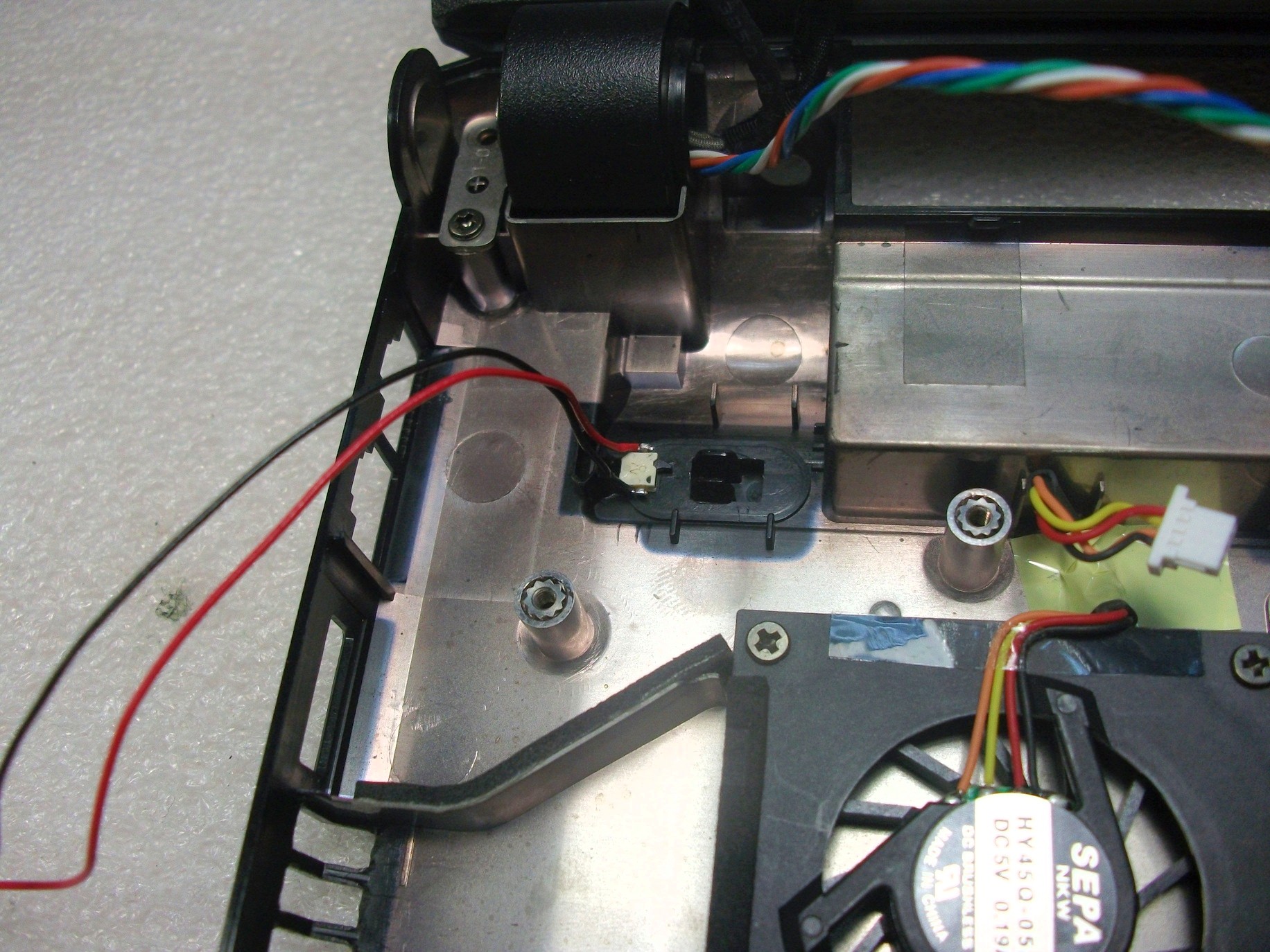
Here you can see that the micro switch opens when the battery is not locked:
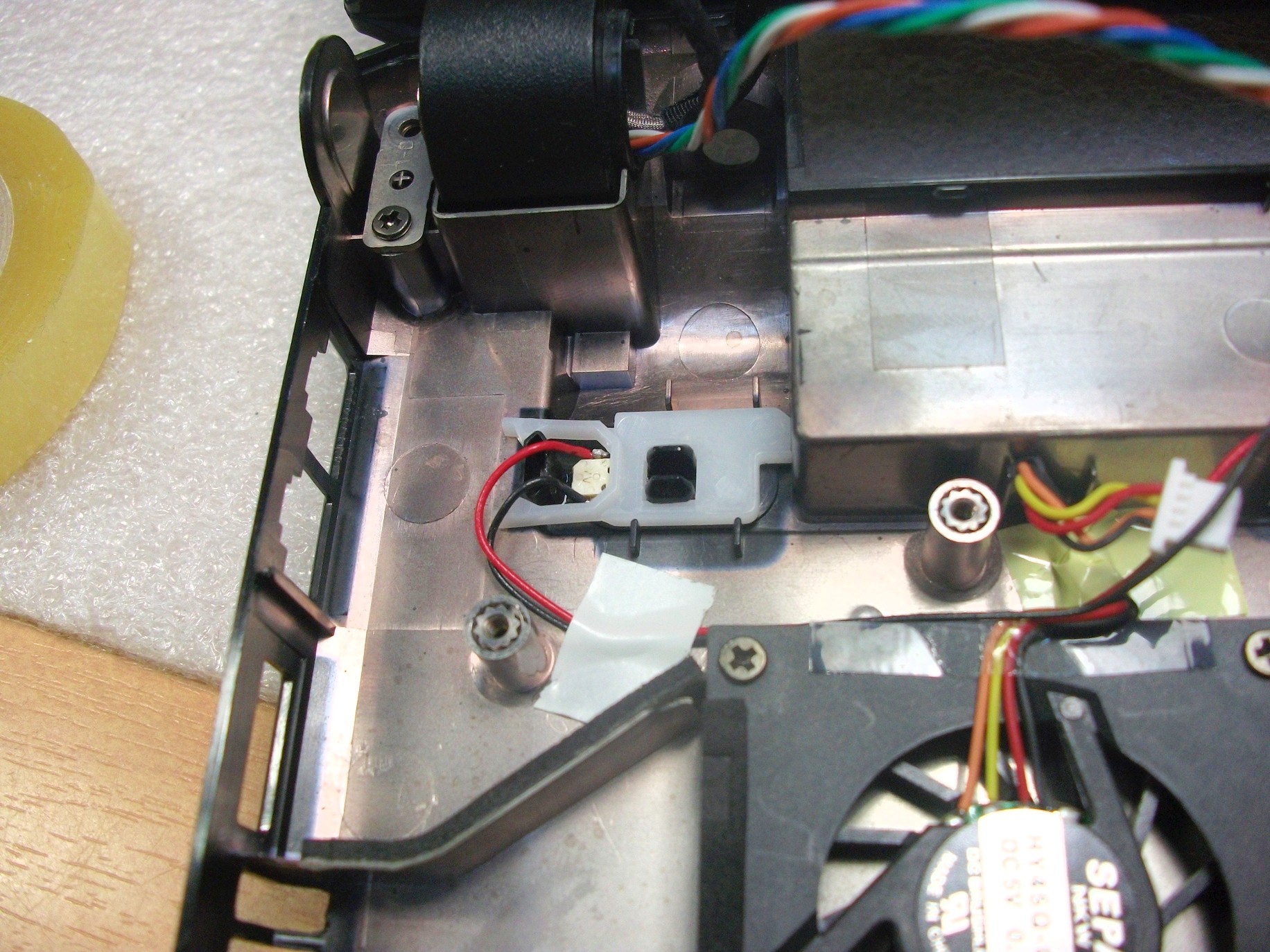
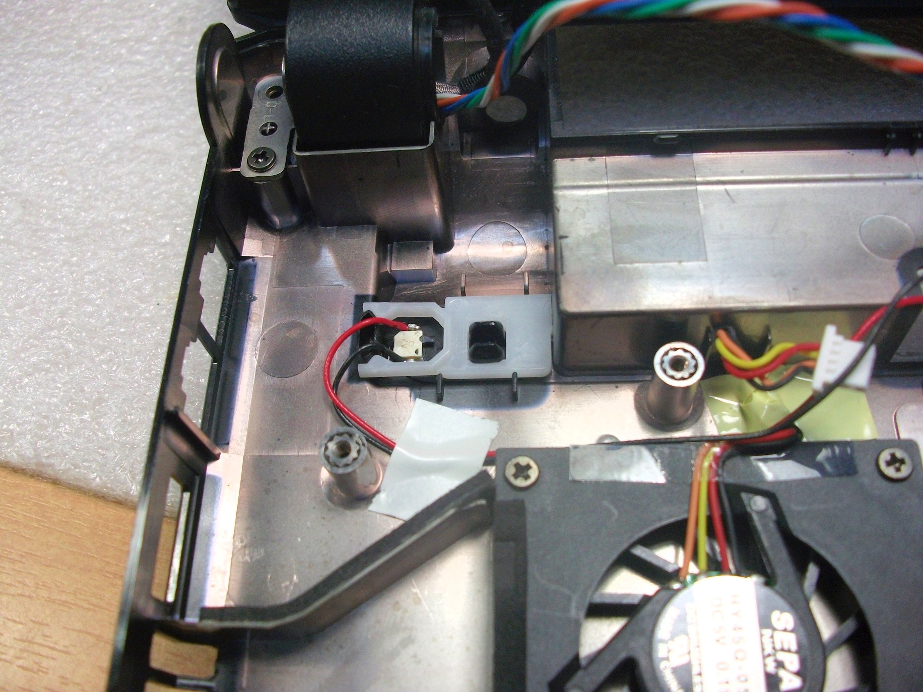
And here he closes:
I dropped the microswitch from an old, inoperative camera. He served there as a sensor for the camera’s open battery compartment.
Now, to turn on the netbook, you need to move the latch to the “closed” position, and after turning it off, move it back to the “open” position.
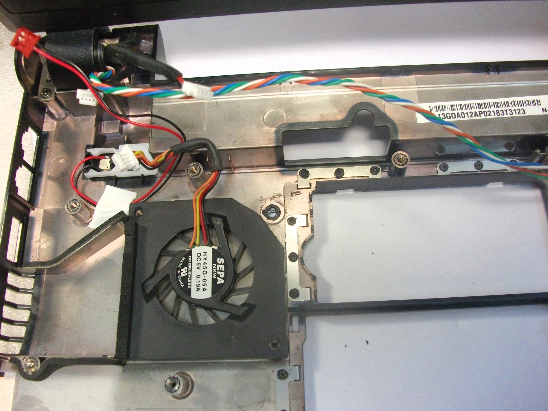
3G modem, cooler
Now I started embedding the 3G modem, this is the most difficult operation, since it takes up a lot of space, it is difficult to solder and it is necessary to lay the antenna cable from it to the edge of the case. It would be easier if I used a thinner cable, and so I had to break one rack under the motherboard and saw off part of the cooler so that the antenna cable could go to the modem.
I decided to make the antenna connector for the 3G modem in the connector for a regular modem - light irony.
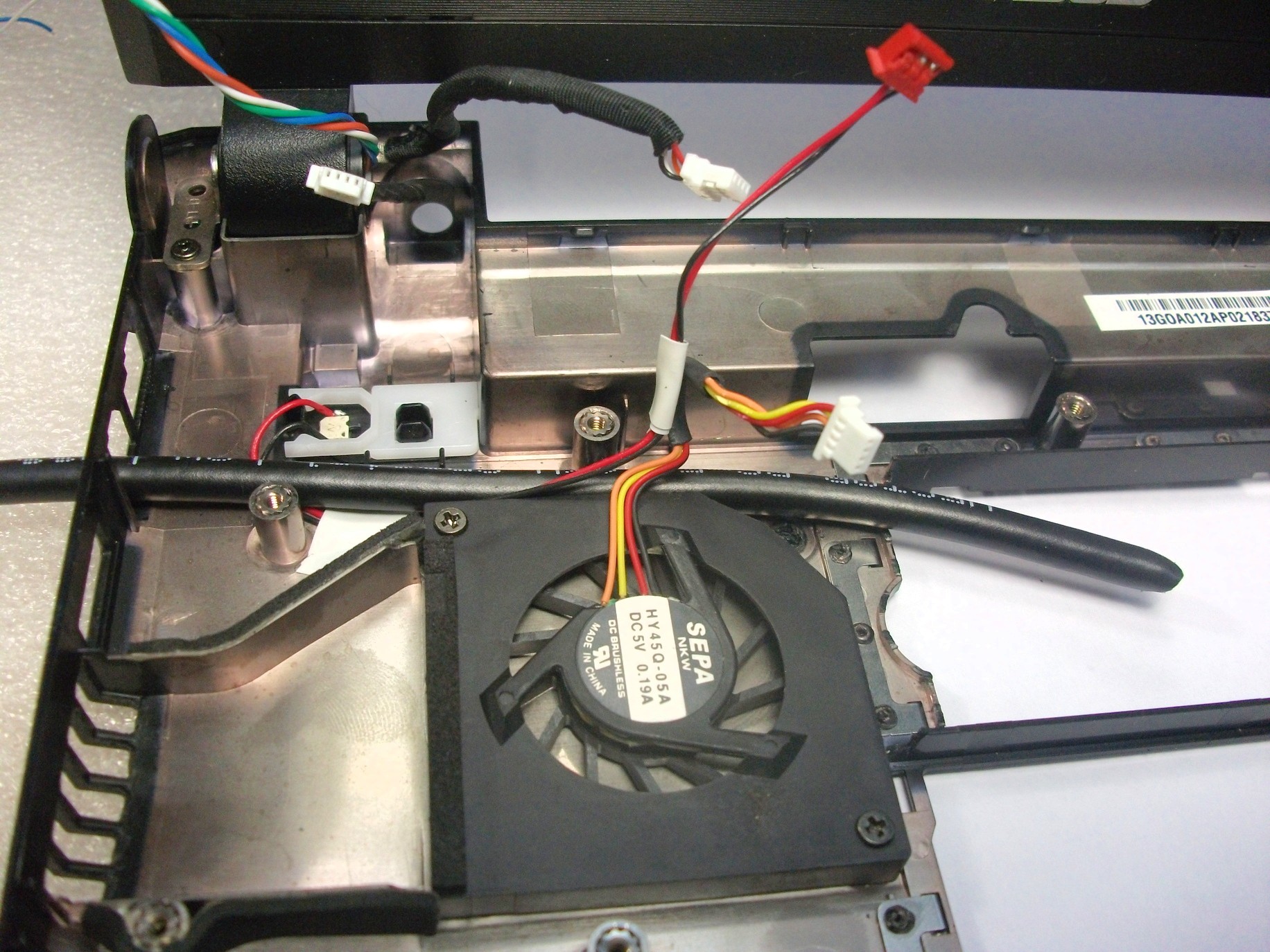
Sawed off part of the cooler so as not to make a hole:
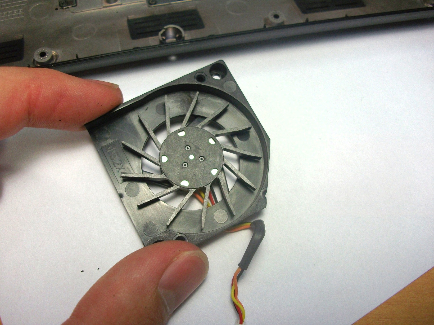
Put it in place:
This is how the antenna cable will go:
3G modem, antenna connector
First you need to get rid of the present telephone jack.
Poured out his contacts:
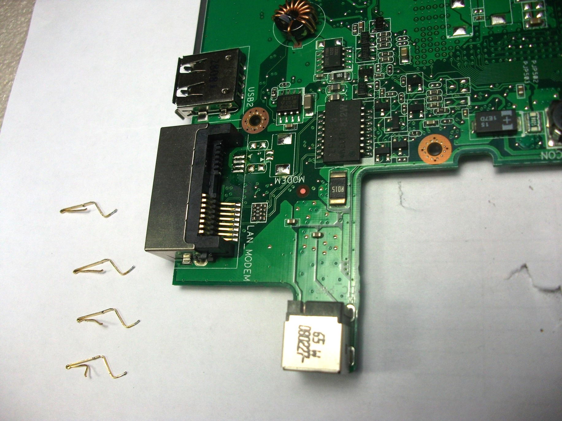
Poked a sufficient hole for the SMA connector:

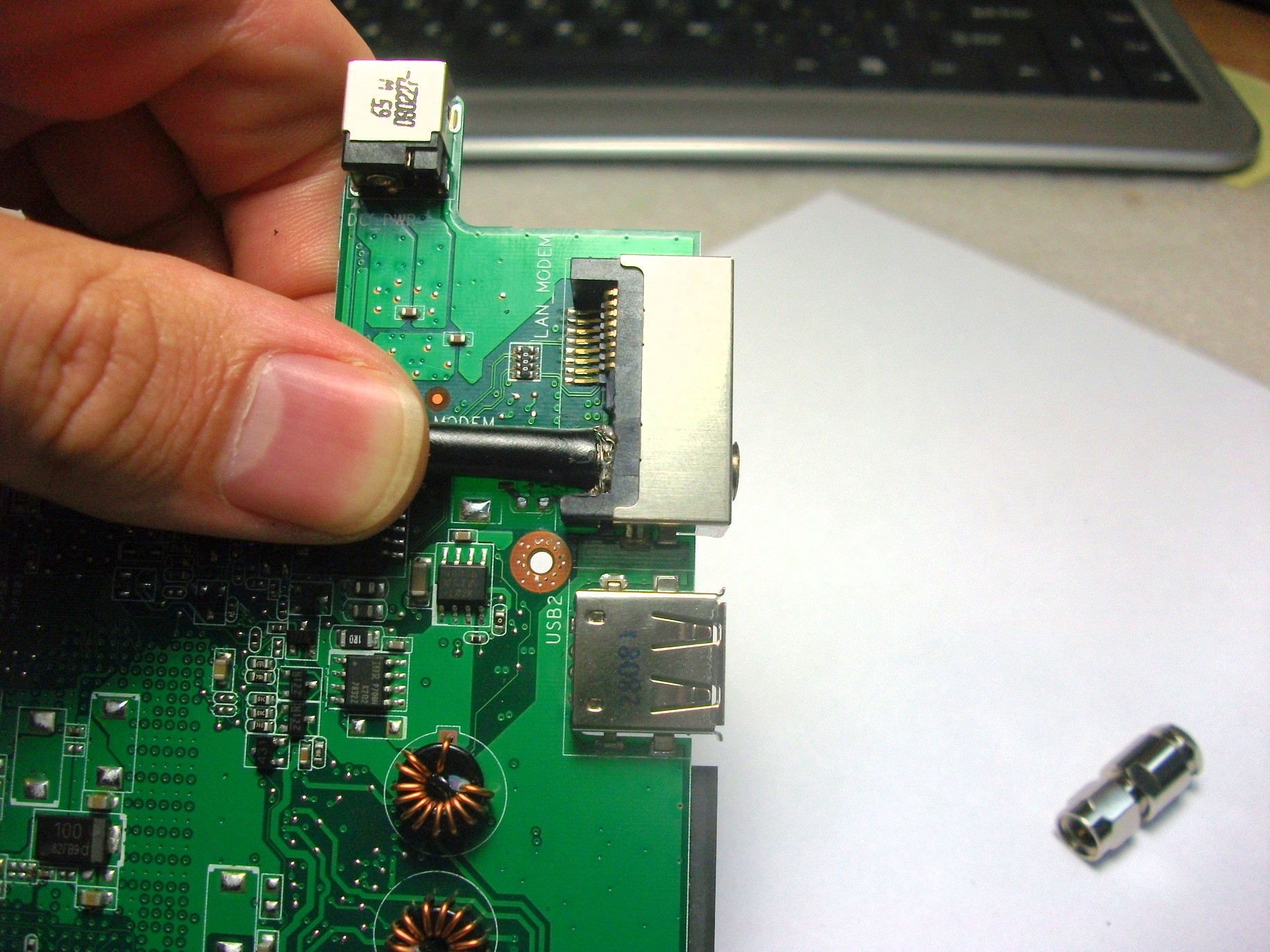
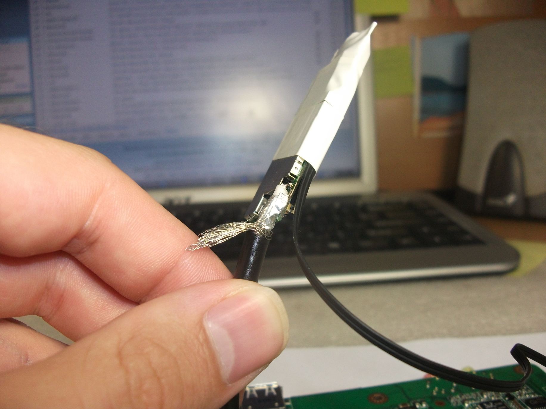
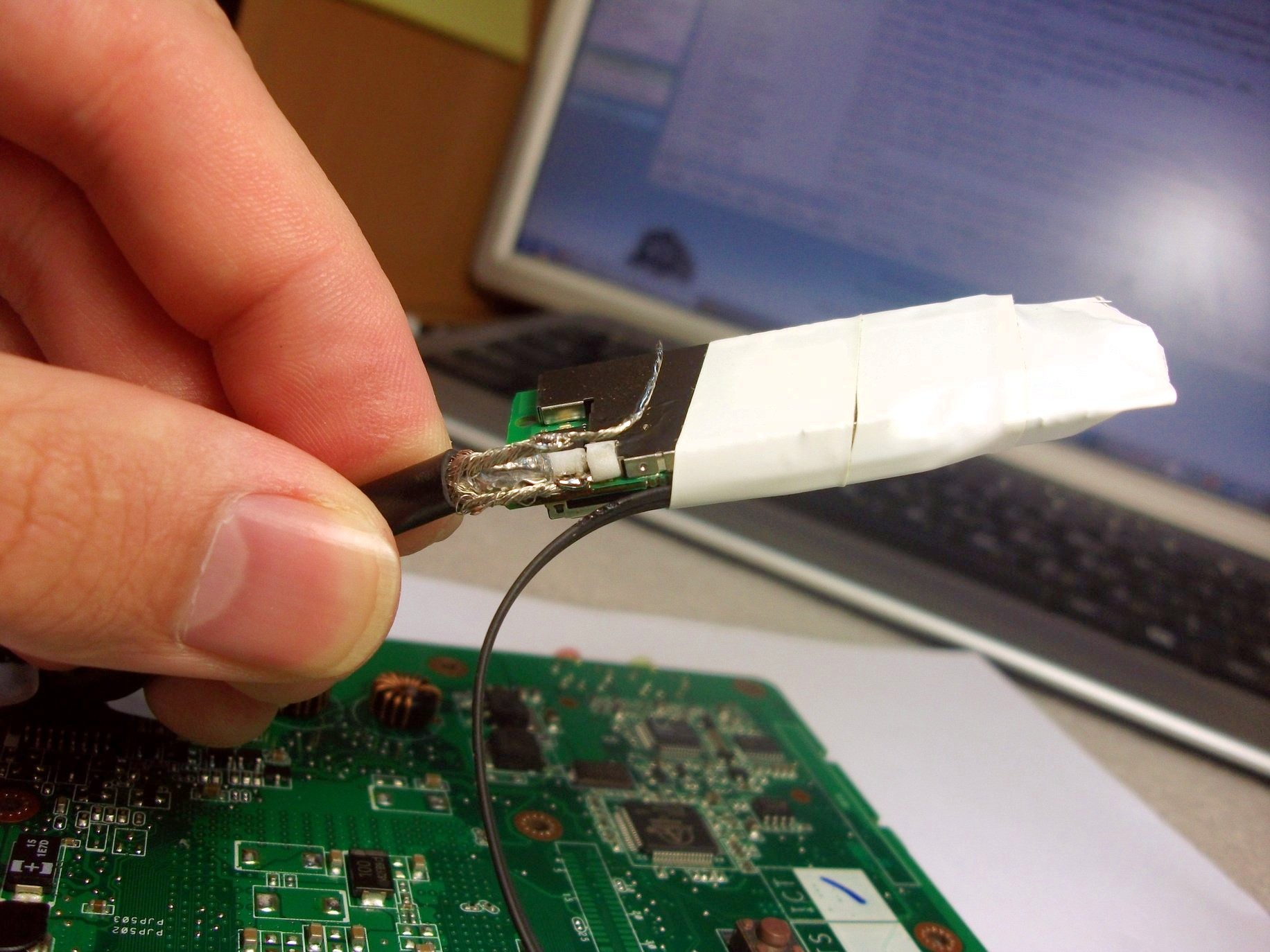
Soldered the connector to the cable:


It was necessary to solder very carefully so as not to overheat the white insulator, but in order to solder the braid to the connector, a high temperature was required, from the second attempt it turned out.
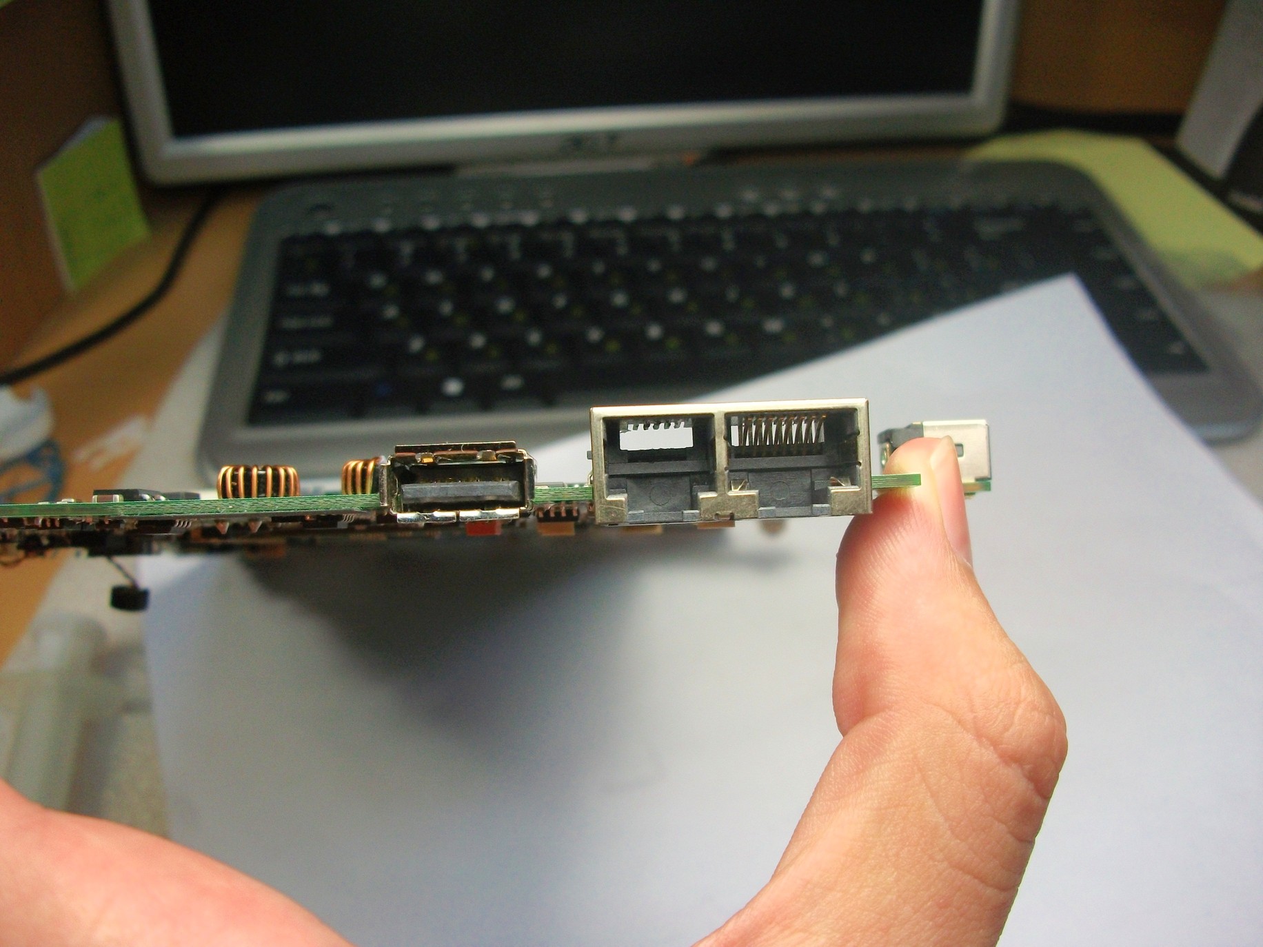
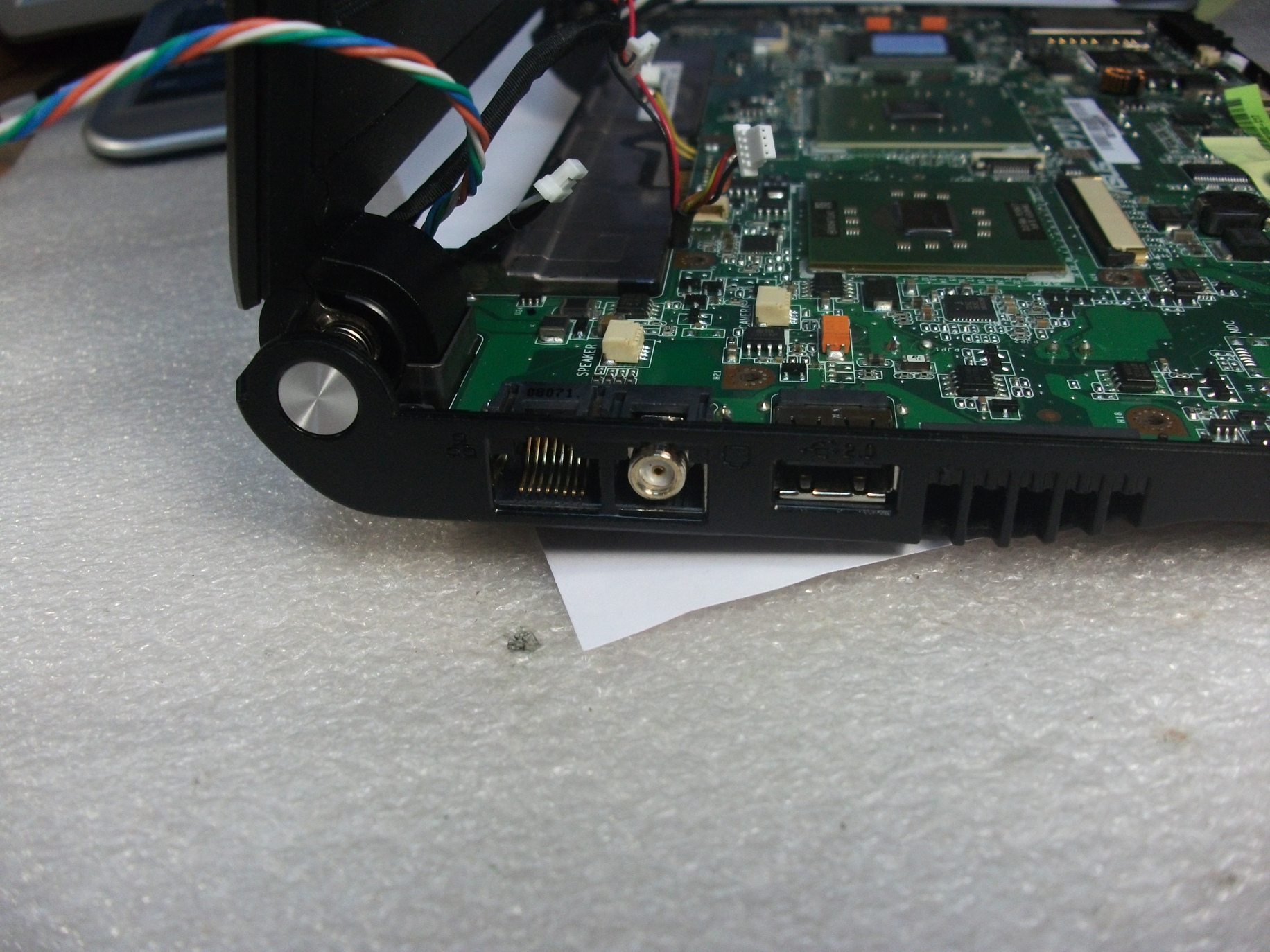
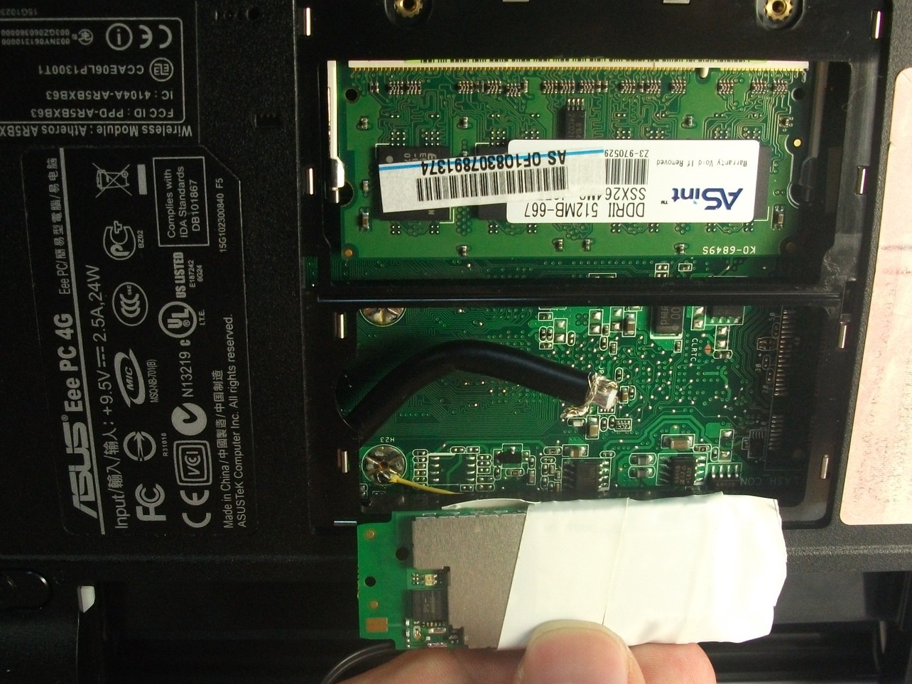
I inserted the cable with the connector into the port:
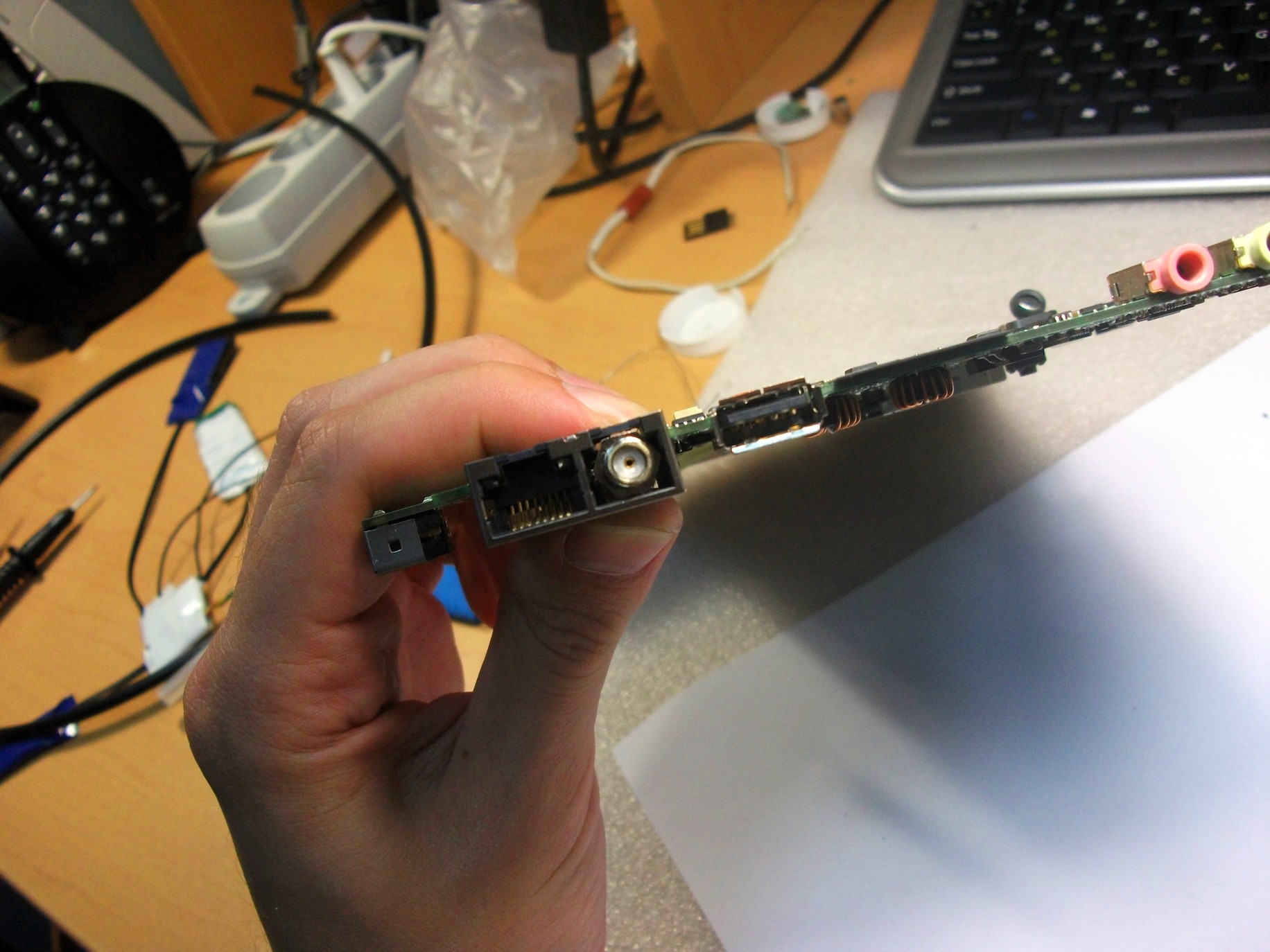
This is how it looks with a wound plug:

And so without:
As you can see, he almost does not protrude from the port and certainly will not protrude from the netbook.
I fixed the cable using
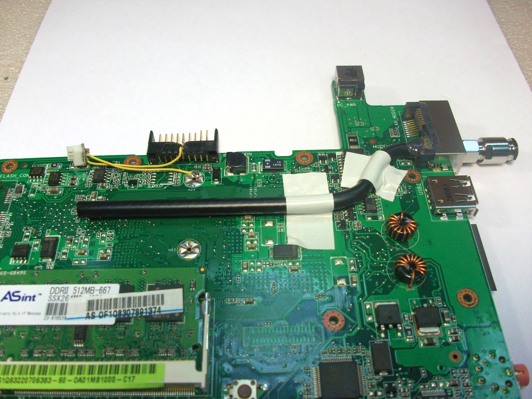
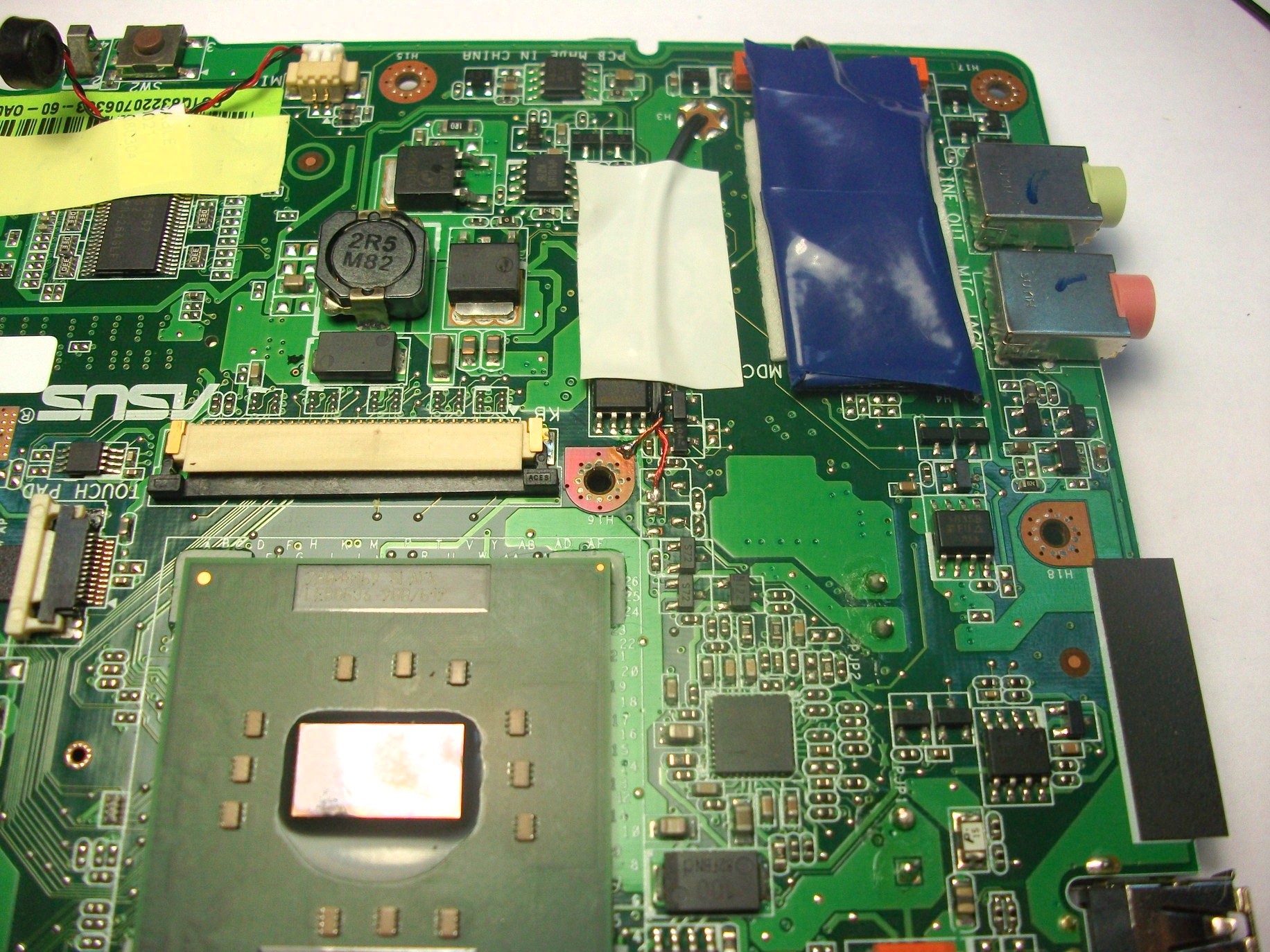
This is how it looks in the case:
The wires from the cooler go over the antenna cable:
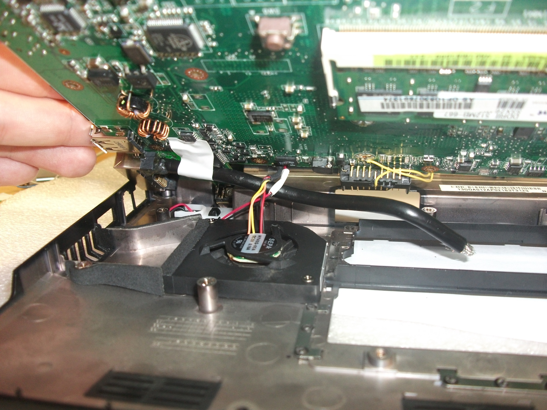
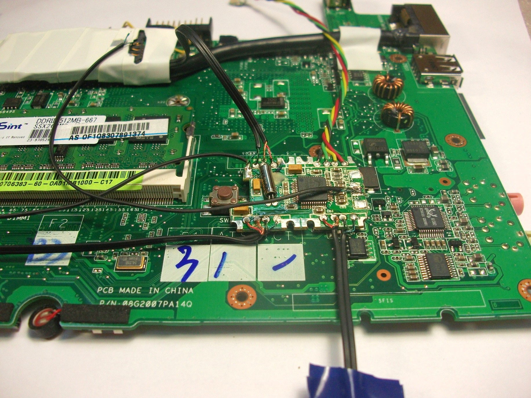
The 3G modem will be located here:
Gently solder the cable to the modem. First, the central core:
And then a braid:
It is very simple to ruin a modem in one sloppy motion.
This is how it looks on the board:

3G modem, antennas
I made antennas for the modem from two WiFi antennas.
I made one portable from a 3dB antenna, counting it on the 3G range:
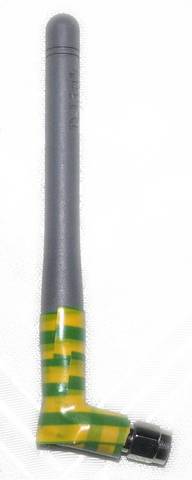
Its actual gain was somewhere around 5..10dBm. Without an antenna, the modem showed a signal of -113dBm, but with this it turned out somewhere -105dBm. Calling (2G) was possible only on the street.
I made another antenna from a WiFi antenna at 5dB. I did not count its structure, as I was quite pleased with how it works. With it, the modem shows approximately -90 ..- 95dBm, calls are confident, audibility is good.

Wiring
Here is the soldered USB hub:
Here the other devices are shown, on the left is an SD reader, on the bottom is a bluetooth module, on top a wire with a white connector will connect to the touchscreen:
Connecting the hub to an idle USB port on the netbook motherboard:

And here I took food for him:
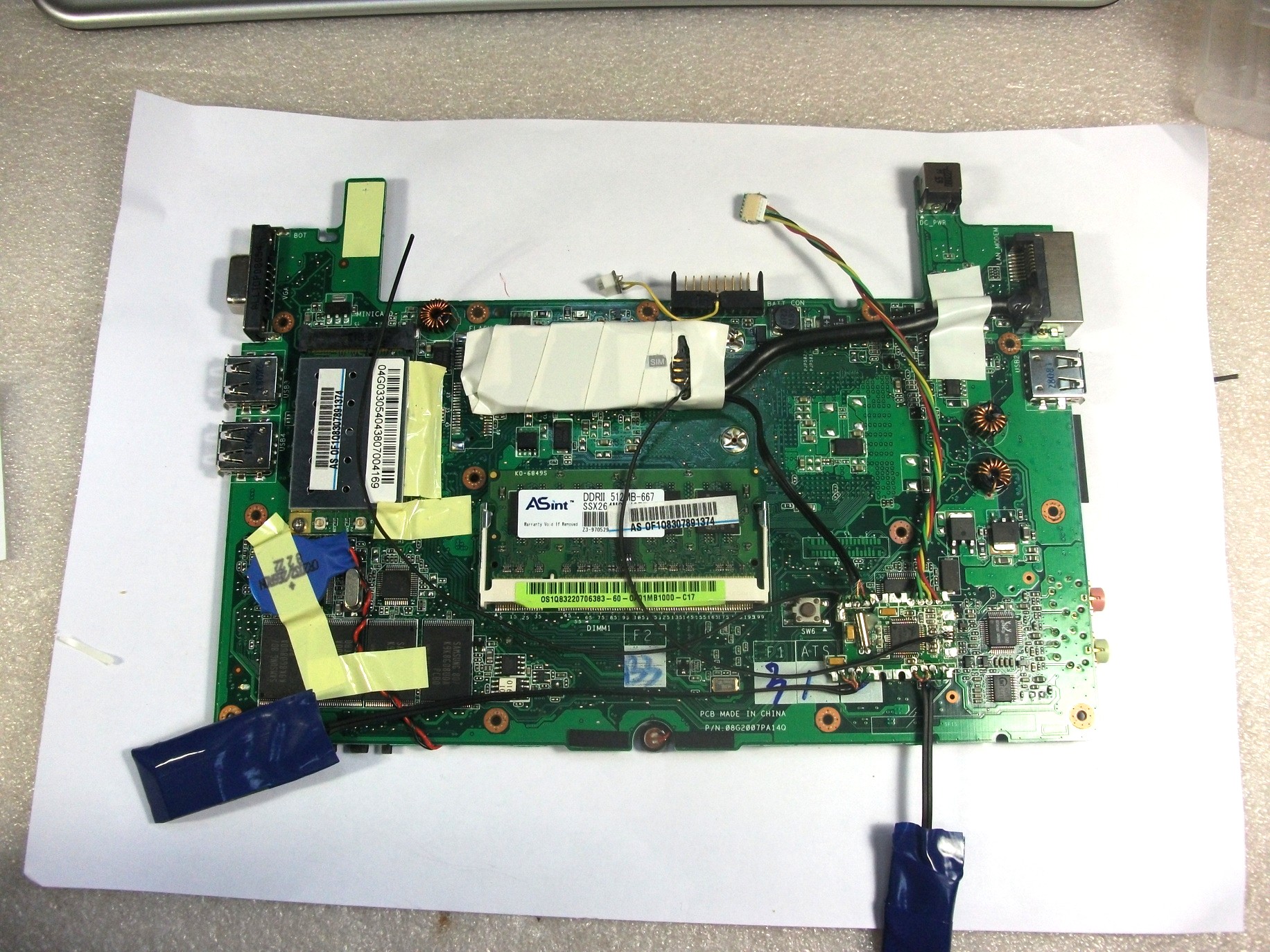
This is how the modules should be located in the end (bottom view):

View from above:
I cut a piece of foil on the top left so that the bluetooth signal was not jammed.
Assembly
After assembling this whole thing, to my chagrin, nothing worked. None of the USB devices were detected in the system.
At this point, free time abruptly ended and there was no time to debug what was done. That was last summer.
But two months ago, I found the same time and finished what I started. It was a matter of bad USB wires, I took them from an optical mouse, replaced them with wires from a good USB cable. There were several short circuits when soldering and a little in the wrong place I supplied power to the USB hub (the power went to the devices connected to it, but not to it myself).
I had to move the SD reader a bit:

Errors have been fixed. In the process of searching for them, my native Windows XP was installed, which I miraculously was able to upgrade to SP3, and which almost immediately after that began to fall out in BSoD. Installed Ubuntu 11.04 b2 and it worked, no problem.
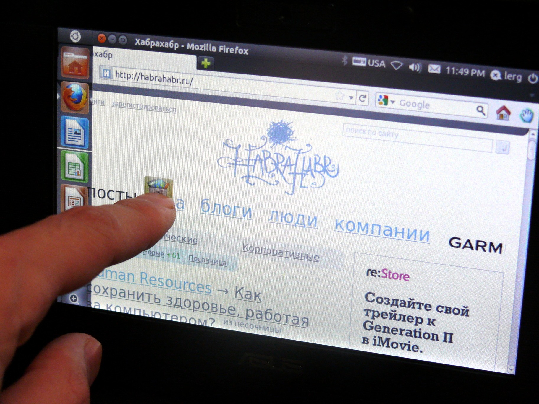
That's all.