Signaling System # 7 / Alarm System No. 7
Signaling System # 7 / Signaling System No. 7 is a set of network protocols for exchanging service messages between mobile stations (mobile phones) and telephone exchanges, as well as between telephone exchanges themselves.
SS # 7 is currently used as a signaling standard in telephone networks.
This article will describe the structure and principle of operation of SS # 7.
All phone calls are made up of two essential components. The first and most obvious is the actual content - our voices, fax data, modem, etc. The second component is the information exchanged between network devices to establish a connection and deliver data to the intended destination.
SS # 7 is a protocol stack that describes how to communicate between telephone switches (switches) in open telephone networks. Used by telephone companies for inter-station signaling. In the past, in-band signaling used inter-station highways. This signaling method provided for one common channel for using both components of telephone calls. This method was not effective and was soon replaced out of band.
For a proper understanding of Signaling System No. 7, first of all, it is necessary to understand the main disadvantages of previous signaling methods used in PSTN (Public Switched Telephone Network). Until the recent past, all telephone connections were carried out by a variety of techniques based on in-band common channel signaling.
A network using out-of-band all-channel signaling is a combination of two networks in one:
SS # 7 is the main inter-station protocol of ISDN. But with no less success it is also used outside of ISDN.
Alarm system No. 7 is an interchangeable set of network elements used for messaging to support telecommunication functions. The SS # 7 protocol is designed to promote these capabilities and to service the network on which they are provided.

Fig. 1 SS # 7 Protocol Stack Structure
Message Transfer Part
At this level, the functions of electron-optical conversion are performed, providing the necessary transmission signal power. MTP1 is compatible with different interfaces (E1, T1).
It performs the following functions: frame synchronization, error checking during transmission of one frame, coordination of the transmission rate, organization of retransmission of frames in which errors are detected.
At this level, 3 types of frames are formed.
MSU (Message Signaling Unit) - a transmission frame that is used to transmit signaling messages (for organizing, breaking connections, etc.).
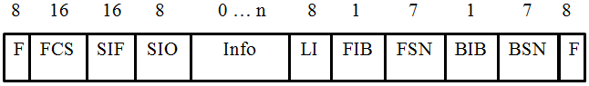
Fig. 2 MSU frame structure
Digits - the number of bits of each field. The purpose of all fields will be described later.
LSSU (Link Status Signal Unit) - transmission frame that carries information about the status of signaling messages, the status of the signaling connection.
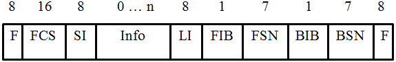
Fig. 3 LSSU FISU frame structure
(Fill In Signaling Unit) - this type of frame does not carry information and is called "empty". It is used in the case of unidirectional transmission of signaling messages by the receiving node to signal the transmitting node about errors and organizing retransmission.
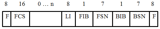
Fig. 4 FISU frame structure
The MTP2 layer forms the transmission frame, supplementing the existing fields (Info, SIO, SIF or SI) with the following fields - F flags, FCS (Frame Check Sequence) control field, LI length indicator (Lenght Indicator), forward indicator bit FIB (Forward Indicator Bit), index bit back BIB (Backward Indicator Bit), sequence number forward FSN (Forward Sequnce Number), sequence number back BSN (Backward Sequnce Number).
In the BSN fieldMSU messages from Node A to Node B enter the number of the last frame received by A from B. If A received an error from B, then A enters the frame number with an error in the BSN field and inserts “1” into the BIB field. B, having received this message, sends the frame again and enters “1” in the FIB field, which means retransmission. FSN
fieldused to indicate the sequence number of the transmitting side, and the BSN is used to indicate the sequence number of the last received frame. That is, sending the first MSU frame, node A enters “0” in the FSN field. If the node B received the frame successfully, generates a response message and writes the number “0” received in the FSN into its FSN field. And, having received a response from B, it reads the FSN field, makes sure that its first frame is successful, forms a second frame and enters “0” in the BSN. Thus, when transmitting the second frame from A to B, node B also receives a report that node A received its response to the first frame without errors. Etc.
With the BIB bit, you can order a retransmission if an error occurs at the reception. “1” is entered if there was “0” if everything went well.
BatThe FIB transmitting party informs the receiving party of the availability of the retransmission.
The functions of this layer coincide with the functions of the network layer of the OSI model. Performs addressing in the SS # 7 network, routing.
On MTP3, the SIO, SIF, and SI fields are generated.
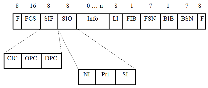
The SIF (Signaling Information Field) field is used to indicate the ID of the signal node, and the code of the node that sends the message ( OPC - Originating Point Code), as well as the code of the node to which this message is assigned ( DPC - Destination Point Code) , is indicated .
Field CIC (Circuit Identity Code) is used to indicate the time interval (time-slot'a), which is used to transmit signaling messages and is located in one of the streams E1, T1. SIO
field(Service Information Octet) is used to identify the type of service. NI (Network Indicator) - network pointer, used to indicate the type of network (national or international network). Pri (Priority) - this field is usually a reserve, in some cases it can be used to indicate priority. SI (Service Indicator) - indicates which type of service the signal message belongs to, which is located in the information field.
At the third level, signal connections between nodes are formed.
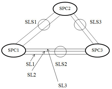
SL (Signaling Link) is the connection between two nodes through which signaling messages are exchanged. As a rule, the number of SL is more than 2.
Two SLs connecting two signaling nodes are usually included in the Signaling Link Set ( SLS ). A set of SLS can contain 2, 3 or more SL, depending on the capacity of the trunk between the PBX.
In the SS # 7 network, there are three types of signal nodes:
SSP (Signaling Switching Point) - a node that performs switching nodes.
SСP (Signaling Control Point) - controls the operation of SSP, contains a database, thereby controlling access to the services that SSP provides.
STP (Signaling Transfer Point) - a node that performs the functions of routing signaling messages.

This level contains a set of protocols that provides the possibility of using SS # 7 in an analogue network of fixed telephony, adapted to a signaling system with a combined channel used in an analogue subscriber line. Not currently used.
A set of protocols that allows the use of SS # 7 in ISDN networks. It supports the principle of operation of all ISDN interfaces, defines the algorithm for forming connections.
Sifnaling Connection Control Part (SCCP) Alarm Link Control
Performs the functions of monitoring connections in the SS # 7 network. Allows you to organize 4 types of data transfer. Each species is characterized by a class from 0 to 3.
Class 0
Formation of connections without coordination between the terminals.
Class 1
Formation of a connection taking into account the sequence number during transmission. Not connection oriented.
Class 2
Formation of the connection with prior approval, after the transfer.
Class 3
Formation of the connection with preliminary coordination, after which there is a data transfer with control of the transmission rate.
Transanction Capability Application Part (TCAP)
Provides data processing functions for remote access equipment. TCAP is used to provide roaming between networks. In this case, the “global translator” service is used, which translates the signal node code (SIF) into the format of a telephone number.
TCAP consists of several sublevels.
A set of protocols that allows the use of SS # 7 in a mobile network. In this case, these protocols support all interfaces of the mobile network, determine the principle of hand-over'a, the principles of the formation of connections.
A set of protocols used to ensure roaming between networks of the same standard, and between networks of different standards (GSM and CDMA, for example).
This protocol suite is for use with SS # 7 in Intelligent Communication Networks (IN). Defines the principle of forming compounds in IN. In this case, it is possible to use authentication as a method of authentication of the subscriber.
SS # 7 is currently used as a signaling standard in telephone networks.
This article will describe the structure and principle of operation of SS # 7.
Introduction
All phone calls are made up of two essential components. The first and most obvious is the actual content - our voices, fax data, modem, etc. The second component is the information exchanged between network devices to establish a connection and deliver data to the intended destination.
SS # 7 is a protocol stack that describes how to communicate between telephone switches (switches) in open telephone networks. Used by telephone companies for inter-station signaling. In the past, in-band signaling used inter-station highways. This signaling method provided for one common channel for using both components of telephone calls. This method was not effective and was soon replaced out of band.
For a proper understanding of Signaling System No. 7, first of all, it is necessary to understand the main disadvantages of previous signaling methods used in PSTN (Public Switched Telephone Network). Until the recent past, all telephone connections were carried out by a variety of techniques based on in-band common channel signaling.
A network using out-of-band all-channel signaling is a combination of two networks in one:
- 1. A circuit-switched network that provides voice and data transmission. Implements a physical channel between the sender and the receiver.
- 2. Alarm network, provides the transmission of service information that controls the call. A packet-switched network using channel-wide switching protocols.
SS # 7 is the main inter-station protocol of ISDN. But with no less success it is also used outside of ISDN.
SS # 7 protocol layers
Alarm system No. 7 is an interchangeable set of network elements used for messaging to support telecommunication functions. The SS # 7 protocol is designed to promote these capabilities and to service the network on which they are provided.
Fig. 1 SS # 7 Protocol Stack Structure
Message Transfer Part
Messaging Subsystem
MTP1
At this level, the functions of electron-optical conversion are performed, providing the necessary transmission signal power. MTP1 is compatible with different interfaces (E1, T1).
MTP2
It performs the following functions: frame synchronization, error checking during transmission of one frame, coordination of the transmission rate, organization of retransmission of frames in which errors are detected.
At this level, 3 types of frames are formed.
MSU (Message Signaling Unit) - a transmission frame that is used to transmit signaling messages (for organizing, breaking connections, etc.).
Fig. 2 MSU frame structure
Digits - the number of bits of each field. The purpose of all fields will be described later.
LSSU (Link Status Signal Unit) - transmission frame that carries information about the status of signaling messages, the status of the signaling connection.
Fig. 3 LSSU FISU frame structure
(Fill In Signaling Unit) - this type of frame does not carry information and is called "empty". It is used in the case of unidirectional transmission of signaling messages by the receiving node to signal the transmitting node about errors and organizing retransmission.
Fig. 4 FISU frame structure
The MTP2 layer forms the transmission frame, supplementing the existing fields (Info, SIO, SIF or SI) with the following fields - F flags, FCS (Frame Check Sequence) control field, LI length indicator (Lenght Indicator), forward indicator bit FIB (Forward Indicator Bit), index bit back BIB (Backward Indicator Bit), sequence number forward FSN (Forward Sequnce Number), sequence number back BSN (Backward Sequnce Number).
In the BSN fieldMSU messages from Node A to Node B enter the number of the last frame received by A from B. If A received an error from B, then A enters the frame number with an error in the BSN field and inserts “1” into the BIB field. B, having received this message, sends the frame again and enters “1” in the FIB field, which means retransmission. FSN
fieldused to indicate the sequence number of the transmitting side, and the BSN is used to indicate the sequence number of the last received frame. That is, sending the first MSU frame, node A enters “0” in the FSN field. If the node B received the frame successfully, generates a response message and writes the number “0” received in the FSN into its FSN field. And, having received a response from B, it reads the FSN field, makes sure that its first frame is successful, forms a second frame and enters “0” in the BSN. Thus, when transmitting the second frame from A to B, node B also receives a report that node A received its response to the first frame without errors. Etc.
With the BIB bit, you can order a retransmission if an error occurs at the reception. “1” is entered if there was “0” if everything went well.
BatThe FIB transmitting party informs the receiving party of the availability of the retransmission.
MTP3
The functions of this layer coincide with the functions of the network layer of the OSI model. Performs addressing in the SS # 7 network, routing.
On MTP3, the SIO, SIF, and SI fields are generated.
The SIF (Signaling Information Field) field is used to indicate the ID of the signal node, and the code of the node that sends the message ( OPC - Originating Point Code), as well as the code of the node to which this message is assigned ( DPC - Destination Point Code) , is indicated .
Field CIC (Circuit Identity Code) is used to indicate the time interval (time-slot'a), which is used to transmit signaling messages and is located in one of the streams E1, T1. SIO
field(Service Information Octet) is used to identify the type of service. NI (Network Indicator) - network pointer, used to indicate the type of network (national or international network). Pri (Priority) - this field is usually a reserve, in some cases it can be used to indicate priority. SI (Service Indicator) - indicates which type of service the signal message belongs to, which is located in the information field.
At the third level, signal connections between nodes are formed.
SL (Signaling Link) is the connection between two nodes through which signaling messages are exchanged. As a rule, the number of SL is more than 2.
Two SLs connecting two signaling nodes are usually included in the Signaling Link Set ( SLS ). A set of SLS can contain 2, 3 or more SL, depending on the capacity of the trunk between the PBX.
In the SS # 7 network, there are three types of signal nodes:
SSP (Signaling Switching Point) - a node that performs switching nodes.
SСP (Signaling Control Point) - controls the operation of SSP, contains a database, thereby controlling access to the services that SSP provides.
STP (Signaling Transfer Point) - a node that performs the functions of routing signaling messages.
Telephony User Part (TUP)
This level contains a set of protocols that provides the possibility of using SS # 7 in an analogue network of fixed telephony, adapted to a signaling system with a combined channel used in an analogue subscriber line. Not currently used.
ISDN User Part (ISUP)
A set of protocols that allows the use of SS # 7 in ISDN networks. It supports the principle of operation of all ISDN interfaces, defines the algorithm for forming connections.
Sifnaling Connection Control Part (SCCP) Alarm Link Control
System
Performs the functions of monitoring connections in the SS # 7 network. Allows you to organize 4 types of data transfer. Each species is characterized by a class from 0 to 3.
Class 0
Formation of connections without coordination between the terminals.
Class 1
Formation of a connection taking into account the sequence number during transmission. Not connection oriented.
Class 2
Formation of the connection with prior approval, after the transfer.
Class 3
Formation of the connection with preliminary coordination, after which there is a data transfer with control of the transmission rate.
Transanction Capability Application Part (TCAP)
Transactional Application Part
Provides data processing functions for remote access equipment. TCAP is used to provide roaming between networks. In this case, the “global translator” service is used, which translates the signal node code (SIF) into the format of a telephone number.
TCAP consists of several sublevels.
Mobile Application Part (MAP)
A set of protocols that allows the use of SS # 7 in a mobile network. In this case, these protocols support all interfaces of the mobile network, determine the principle of hand-over'a, the principles of the formation of connections.
IS 45
A set of protocols used to ensure roaming between networks of the same standard, and between networks of different standards (GSM and CDMA, for example).
Inteligent Network Application Part (INAP)
This protocol suite is for use with SS # 7 in Intelligent Communication Networks (IN). Defines the principle of forming compounds in IN. In this case, it is possible to use authentication as a method of authentication of the subscriber.