February 6, 2011 at 20:20
Operational Amplifiers (based on the simplest examples): Part 3
- Tutorial
Brief introduction
I continue to write
Topic Overview
You may have already come across RC, LC, and RLC filter models. They are quite suitable for most tasks. But for some purposes it is very important to have filters with flatter bandwidth characteristics and steeper slopes. Here we need active filters.
To refresh my memory, let
me remind you what filters there are: Low Pass Filter (LPF) - passes a signal that is below a certain frequency (it is also called the cutoff frequency). Wikipedia
High Pass Filter (HPF) - passes a signal above the cutoff frequency. Wikipedia Band Pass
Filter - Passes only a specific frequency range. Wikipedia
Notch Filter - Delays only a certain frequency range.Wikipedia
Well, some more lyrics. Look at the amplitude-frequency response (AFC) of the HPF. On this graph, do not look for anything interesting yet, but just pay attention to the sections and their names:

The most commonplace examples of active filters can be seen here in the "Integrators and Differentiators" section. But in this article we will not touch these schemes, because they are not very effective.
Choose a filter
Suppose that you have already decided on the frequency you want to filter. Now you need to determine the type of filter. More precisely, you need to choose its characteristic. In other words, how the filter will behave.
The main characteristics are:
Butterword Filter - has the flattest response in the passband, but has a smooth drop.
Chebyshev filter - has the steepest decline, but it has the most uneven characteristics in the passband.
Bessel filter - has a good phase-frequency response and a completely “decent” decline. It is considered the best choice if there is no specific task.
Some more information
Suppose you completed this task. And now you can safely proceed to the calculations.
There are several calculation methods. We will not complicate and use the simplest. And the simplest is the tabular method. Tables can be found in the relevant literature. Whatever you seek for a long time, I will bring from Horowitz and Hill the “Art of Circuit Engineering”.
For the low-pass filter:
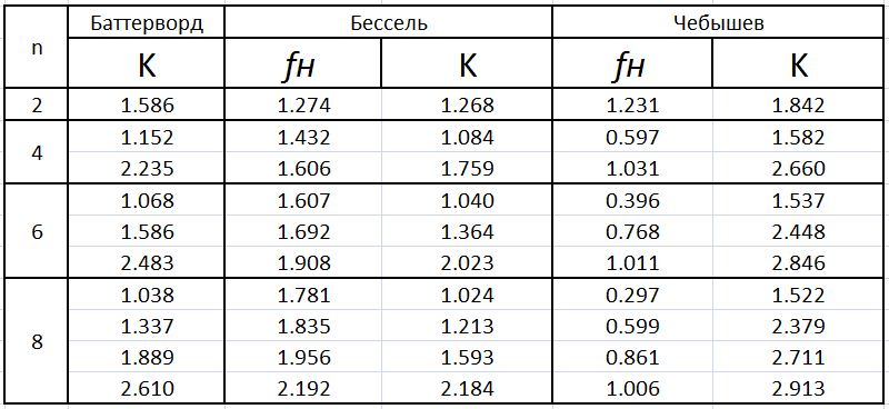
Let's just say that you could find and read all this in the literature. We turn specifically to the design of filters.
Payment
In this section I will try to briefly “go over” all types of filters.
So, task # 1 . Build a second-order low-pass filter with a cutoff frequency of 150 Hz according to Butterworth characteristic.
Let's get started. If we have a filter of nth even order, this means that there will be n / 2 opamps in it. In this assignment - one.
LPF scheme:
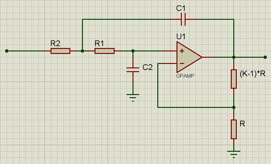
For this type of calculation, it is taken into account that R1 = R2 , C1 = C2 .
We look at the tablet. We see that K = 1.586 . This will come in handy later.
For a low-pass filter, it is true:,
 where, of course,
  is the cutoff frequency.
 After counting, we get
 . Now let's get to the selection of elements. They determined the op-amp - “ideal” in the amount of 1 pc. From the previous equality it can be assumed that it does not matter to us which element to choose “first”. Let's start with a resistor. Best of all, its resistance value should be in the range from 2kOhm to 500kOhm. In the eye, let it be 11 kOhm. Accordingly, the capacitance of the capacitor becomes 0.1 μF. For feedback resistors, we take the value of R arbitrarily. I usually take 10 kOhm. Then, for the top, we take the value of K from the table. Therefore, the lower one will have a resistance value of R = 10 kOhm, and the upper one will have 5.8 kOhm.
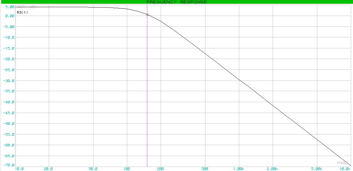
 We collect and model the frequency response.
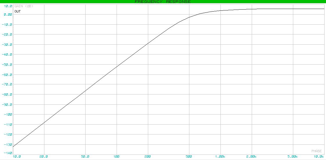
Task # 2 . Build a fourth-order high-pass filter with a cut-off frequency of 800 Hz according to the Bessel characteristic.
We decide. Once a fourth-order filter, there will be two opamps in the circuit. Everything here is not at all complicated. We simply cascade 2 HPF circuits.
The filter itself looks like this:

The fourth-order filter looks like this :
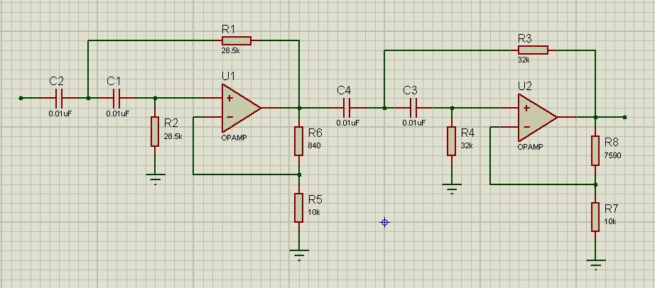
Now the calculation. As you can see, for the fourth-order filter, we already have 2 K values . It is logical that the first is intended for the first cascade, the second - for the second. The values of K are 1.432 and 1.606, respectively. The table was for low-pass filters (!). To calculate the HPF, something needs to be changed. The coefficients K remain the same in any case. For the characteristics of Bessel and Chebyshev, the parameter changes
 - the normalizing frequency. It will be equal now:
For Chebyshev and Bessel filters, the same formula is true for both low and high frequencies:

Note that for each individual cascade it will have to be considered separately.
For the first stage:

Let C = 0.01 μF, then R = 28.5 kOhm. Feedback resistors: lower, as usual, 10 kOhm; upper - 840 ohms.
For the second stage:

The capacitance of the capacitor is left unchanged. Once C = 0.01 μF, then R = 32 kOhm.
We are building the frequency response.
To create a band or notch type of filters, you can cascade the low-pass and high-pass filters. But these types are often not used due to poor performance.
For band-pass and notch filters, you can also use the "tabular method", but here are slightly different characteristics.
I’ll give a tablet right away and explain it a bit. So as not to stretch much - the values are taken immediately for a fourth-order bandpass filter.

a1 and b1 are the calculated coefficients. Q - Q factor. This is a new option. The greater the value of the quality factor, the more “sharp” the recession will be. Δf is the range of transmitted frequencies, and sampling is at the level of -3 dB. Coefficient α is another calculated coefficient. It can be found using formulas that are fairly easy to find on the Internet.
Alright, that's enough. Now the work task.
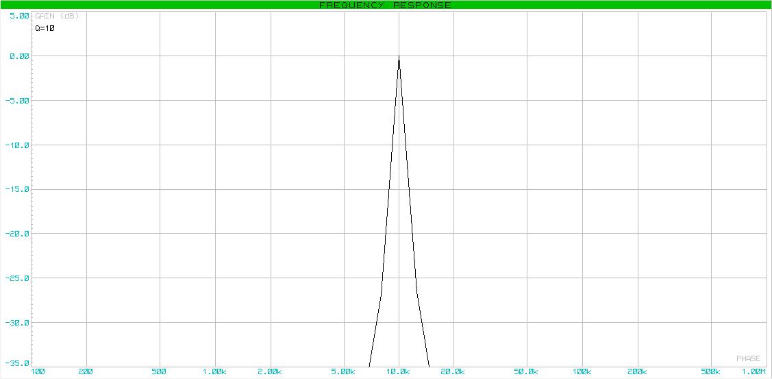
Task # 3. Build a fourth-order bandpass filter according to the Butterward characteristic with a center frequency of 10 kHz, a width of transmitted frequencies of 1 kHz and a gain at the center frequency point of 1.
Let's go. Fourth order filter. So two opamps. I’ll give a typical diagram right away with calculated elements.
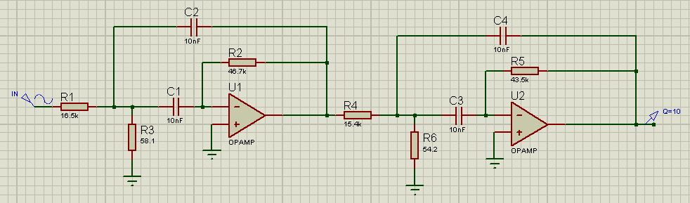
For the first filter, the center frequency is defined as:

For the second filter:

Specifically, in our case, again from the table, we determine that the Q factor is Q = 10. We calculate the Q factor for the filter. Moreover, it is worth noting that the quality factor of both will be equal.

Gain correction for the center frequency region:

The final stage is component calculation.
Let the capacitor be equal to 10 nF. Then, for the first filter:



In the same order as (1) we find R22 = R5 = 43.5 kOhm, R12 = R4 = 15.4 kOhm, R32 = R6 = 54.2 Ohm. Just keep in mind that for the second filter we use

Well and lastly, the frequency response.
The next stop is bandpass or notch filters.
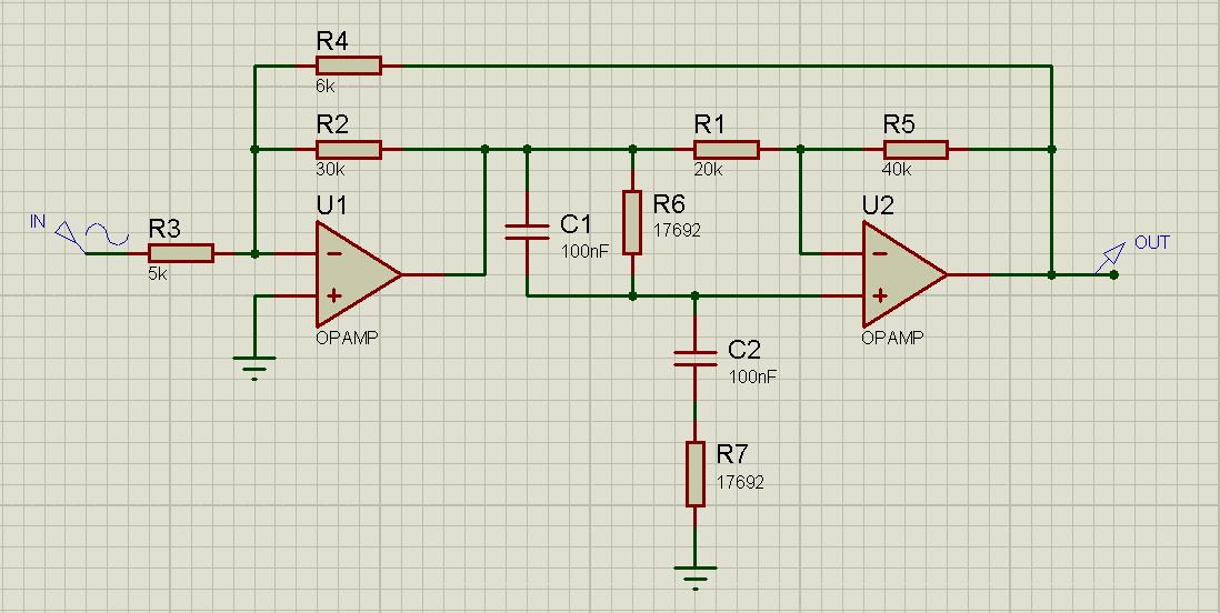
There are several variations. Probably the easiest is the Active Wien-Robinson Filter. A typical circuit is also a 4th order filter.
Our last assignment.
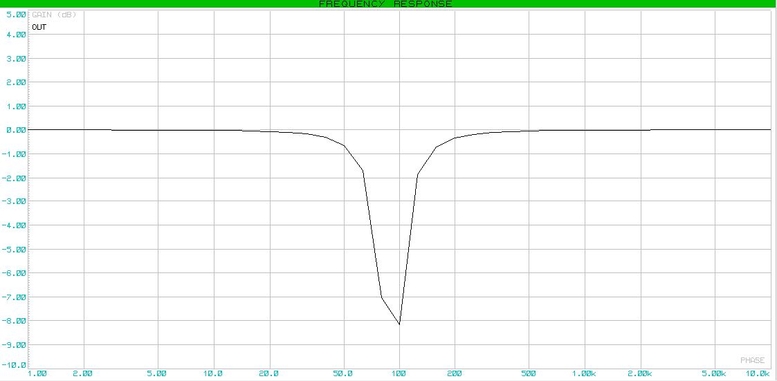
Task # 4 . Build a notch filter with a central frequency of 90 Hz, Q factor Q = 2 and gain in the passband equal to 1.
First of all, randomly select the capacitor capacitance. Let's sayC = 100 nF.
We define the value R6 = R7 = R :

It is logical that “playing” with these resistors, we can change the frequency range of our filter.
Next, we need to determine the intermediate coefficients. We find them through the quality factor.


Choose an arbitrary resistor R2 . In this particular case, it is best that it is 30 kOhm.
Now we can find resistors that will adjust the gain in the passband.


And lastly, you must arbitrarily choose R5 = 2R1 . In my circuit, these resistors have a value of 40 kOhm and 20 kOhm, respectively.
Actually, the frequency response:
Almost end
To whom it is interesting to learn a little more, I can advise you to read Horowitz and Hill "The Art of Circuit Engineering".
Also, D. Johnson “A handbook of active filters”.
Wikipedia
Also, who do not really need calculations, but who need the filters themselves, I can advise the useful software
P.S. Add a very useful link and its mirror . Thanks for the link spiritus_sancti