Cable with timer for digital cameras Canon
It is no secret that when shooting at slow shutter speeds the photographer is saved by a tripod and a control panel (“cable”). If a tripod can be purchased almost everywhere, and there are good models worth even 600-700 rubles, then things are not so rosy with the remote control. The price tag for branded Canon remotes starts at $ 30, but meanwhile inside this remote contains only the simplest switching scheme. To shoot a time-lapse video, you will have to purchase a remote control with a timer (Canon branded - $ 210, the Chinese brothers are reasonably cheaper). I want to show how, without the use of complex electronics and controllers, to independently assemble a functional "cable" with a timer that will fit Canon cameras of the EOS-300D / 350D / 400D / 450D series and possibly some other one.
Let's start with a simple one, but this is probably enough for someone. For the usual “cable” button, you will need two buttons, one switch, a 2.5 mm plug-jack and a wire (I took the old wire from a computer mouse). They need to be connected as shown in the diagram below. It also shows which part of the plug is connected to.

Here S1 and S2 are buttons, shooting occurs if you hold “Autofocus” and press “Shutter”. S3 - the switch closes the autofocus circuit, and makes it possible to shoot just by pressing the shutter release.
You can buy a case for this device (like this one ), or you can show your imagination and put it in an egg from Kinder Surprise or a box from Tick-Tak (I had just that):

But we will not stop at a simple remote, but add a timer to it and combine everything into one device. The task of the timer is to “press” the trigger once in a certain number of seconds. Obviously, the close contacts of the external signal is the well-known device: relays . But in order to reduce the device and increase reliability, we use an optical relay. I used KR293KP2A because of the low control voltage and current (only 1.3V / 5mA), cheapness and size.
It remains to deal with the control circuit for the relay. The best solution would be a rectangular pulse generator with a period equal to the shooting period we set. You can assemble such a generator on separate transistors, or you can use microcircuits. I just lay around the NE555 single-chip microcircuit (there is a datasheet on it, for example, here ) and I decided to use it.
The datasheet shows the reference circuit of the pulse generator, and we will collect it. A complete diagram of the entire device is shown in Figure 2. In this embodiment, the U1 chip works as a multivibrator. Figure 1 shows a graph of the generated pulses.

Figure 1 - Graph of generated pulses
The period t1 corresponds to the charge time of the capacitor C1, the period t2 to the time of its discharge. The first trick we'll go about is the inverter. More precisely, his absence. The graph shows that almost all the time the shutter button will be “pressed”. But if you set the camera to a single shooting mode, then after the leading edge of the pulse (and, therefore, the operation of the opto-relay), the shutter will “click”, and after the exposure time the mirror will snap into place. The camera will have enough reset time t2 to start waiting for the next click. The battery in this use case is consumed in the same way as with ordinary manual shooting.
The datasheet shows the calculation formulas t1 and t2. Since C1 is charged through the chain of R3 and R1, the period t1 = 0.693 * (R1 + R3) * C1. The period t2 corresponding to the discharge through R1 is 0.693 * R1 * C1. It is clear that we can adjust the time by changing the resistance value R3. Having set the norm of the timer values from 1 to 70 seconds, we obtain, taking into account the existing values of the elements, the resistance and capacitance values indicated on the diagram. It is worth noting here that when R3 was set to the extreme position corresponding to zero, the generation was disrupted, so R2 had to introduce very little resistance and it worked.
Since the optical relay is controlled by a voltage of no higher than 1.5V and a current of 5-10mA, we will assemble the corresponding voltage divider on R4 and R5. It is calculated taking into account the fact that with a supply voltage of 9V at the output of the multivibrator, the signal voltage will be about 7V (according to data from the datasheet).
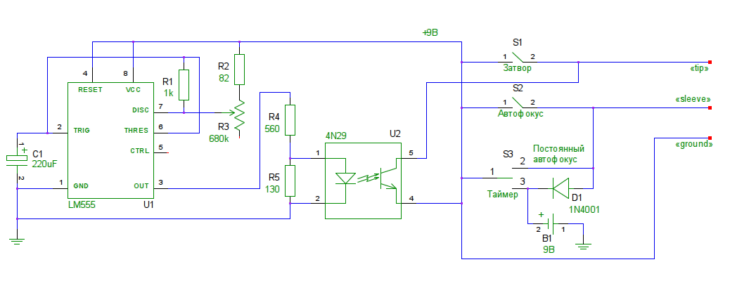
Figure 2 - Complete device diagram
The second trick is connected with the union of two "cables" into one. First, in order for the timer to “press” the shutter, the AF lock must be turned on. Secondly, it makes no sense to supply power to the timer when it is not really needed. So I used the on-off switch S3. In the upper position, it simply turns on autofocus, while the voltage is not supplied to the circuit due to diode D1. In the lower position, both the autofocus circuit and the timer power circuit are simultaneously closed. Please note that the power of the timer is electrically isolated from the autofocus circuit, despite the fact that the “+” voltage is supplied through the same wire as the “earth” of the camera, since they have a different “earth”.
It remains to assemble everything together, carefully checking the connections (I soldered the circuit on the circuit board, cutting out a 3x3 cm square from it). It will be more difficult to select a housing from improvised materials here, so I bought a ready-made housing with a battery compartment. As a result, we got such a device:
In development plans: add a timer power indicator and try to make a photo synchronizer - add a circuit with a phototransistor to the shutter button, which is displayed on the case (this will help to remove, for example, lightning). Well, in the end, replace most of the filling with a microcontroller with information displayed on the display and greater accuracy and the range of the set time.
Simple control panel
Let's start with a simple one, but this is probably enough for someone. For the usual “cable” button, you will need two buttons, one switch, a 2.5 mm plug-jack and a wire (I took the old wire from a computer mouse). They need to be connected as shown in the diagram below. It also shows which part of the plug is connected to.
Here S1 and S2 are buttons, shooting occurs if you hold “Autofocus” and press “Shutter”. S3 - the switch closes the autofocus circuit, and makes it possible to shoot just by pressing the shutter release.
You can buy a case for this device (like this one ), or you can show your imagination and put it in an egg from Kinder Surprise or a box from Tick-Tak (I had just that):
Timer Control Panel
But we will not stop at a simple remote, but add a timer to it and combine everything into one device. The task of the timer is to “press” the trigger once in a certain number of seconds. Obviously, the close contacts of the external signal is the well-known device: relays . But in order to reduce the device and increase reliability, we use an optical relay. I used KR293KP2A because of the low control voltage and current (only 1.3V / 5mA), cheapness and size.
It remains to deal with the control circuit for the relay. The best solution would be a rectangular pulse generator with a period equal to the shooting period we set. You can assemble such a generator on separate transistors, or you can use microcircuits. I just lay around the NE555 single-chip microcircuit (there is a datasheet on it, for example, here ) and I decided to use it.
The datasheet shows the reference circuit of the pulse generator, and we will collect it. A complete diagram of the entire device is shown in Figure 2. In this embodiment, the U1 chip works as a multivibrator. Figure 1 shows a graph of the generated pulses.
Figure 1 - Graph of generated pulses
The period t1 corresponds to the charge time of the capacitor C1, the period t2 to the time of its discharge. The first trick we'll go about is the inverter. More precisely, his absence. The graph shows that almost all the time the shutter button will be “pressed”. But if you set the camera to a single shooting mode, then after the leading edge of the pulse (and, therefore, the operation of the opto-relay), the shutter will “click”, and after the exposure time the mirror will snap into place. The camera will have enough reset time t2 to start waiting for the next click. The battery in this use case is consumed in the same way as with ordinary manual shooting.
The datasheet shows the calculation formulas t1 and t2. Since C1 is charged through the chain of R3 and R1, the period t1 = 0.693 * (R1 + R3) * C1. The period t2 corresponding to the discharge through R1 is 0.693 * R1 * C1. It is clear that we can adjust the time by changing the resistance value R3. Having set the norm of the timer values from 1 to 70 seconds, we obtain, taking into account the existing values of the elements, the resistance and capacitance values indicated on the diagram. It is worth noting here that when R3 was set to the extreme position corresponding to zero, the generation was disrupted, so R2 had to introduce very little resistance and it worked.
Since the optical relay is controlled by a voltage of no higher than 1.5V and a current of 5-10mA, we will assemble the corresponding voltage divider on R4 and R5. It is calculated taking into account the fact that with a supply voltage of 9V at the output of the multivibrator, the signal voltage will be about 7V (according to data from the datasheet).
Figure 2 - Complete device diagram
The second trick is connected with the union of two "cables" into one. First, in order for the timer to “press” the shutter, the AF lock must be turned on. Secondly, it makes no sense to supply power to the timer when it is not really needed. So I used the on-off switch S3. In the upper position, it simply turns on autofocus, while the voltage is not supplied to the circuit due to diode D1. In the lower position, both the autofocus circuit and the timer power circuit are simultaneously closed. Please note that the power of the timer is electrically isolated from the autofocus circuit, despite the fact that the “+” voltage is supplied through the same wire as the “earth” of the camera, since they have a different “earth”.
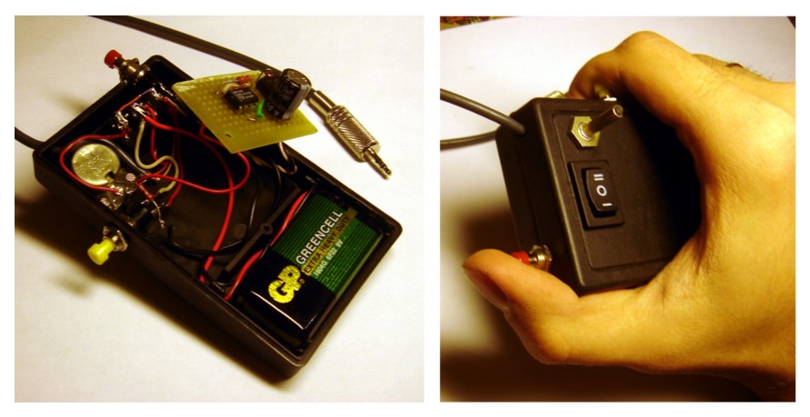
It remains to assemble everything together, carefully checking the connections (I soldered the circuit on the circuit board, cutting out a 3x3 cm square from it). It will be more difficult to select a housing from improvised materials here, so I bought a ready-made housing with a battery compartment. As a result, we got such a device:
In development plans: add a timer power indicator and try to make a photo synchronizer - add a circuit with a phototransistor to the shutter button, which is displayed on the case (this will help to remove, for example, lightning). Well, in the end, replace most of the filling with a microcontroller with information displayed on the display and greater accuracy and the range of the set time.