Analog-to-digital signal conversion for beginners
Introduction
The topics of analog-to-digital and digital-to-analog conversions are quite important in the course of electronics, since most devices that interact with a computer have analog input / output, and the computer can only process digital signals. In this article I want to share with you the very basics of such transformations.
Signal types
Before you understand the transformations themselves, you need to know what signals exist. And there are 3 types of them:
- Analog
- Discrete
- Digital
Analogue signals are continuous in time; they are determined at all time instants.
Discrete - these are signals represented by a sequence of samples, i.e. signal values at discrete time instants.
Digital signals are discrete in time (or in space) and quantized in level. Computational procedures in a computer are performed precisely in digital signals.
In order for the computer to be able to process the signal, it is necessary to convert the signal from analog to digital form.
After processing, the inverse conversion is performed, since most household devices are controlled by analog signals.
The block diagram of digital signal processing in general is as follows:
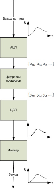
Analog to Digital Signal Conversion
Analog-to-digital signal conversion includes two stages:
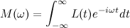
- Signal discretization (in time or space)
- Level Quantization
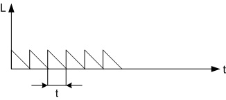
At the sampling stage, signal samples with a certain sampling period (T) are taken.
The sampling frequency can be determined by the formula.

The process of obtaining a sample of the input signal must occupy a very small part of the sampling period in order to reduce the dynamic conversion errors due to a change in the signal during the sampling time.
The sampling rate is selected from the Kotelnikov theorem . It states that in order for the continuous signal to be restored arbitrarily accurately from the samples of the signal, the sampling frequency must be at least two times higher than the upper frequency of the spectrum of the sampled signal.
Any signal has its own spectral representation. Any representation of a signal is a representation in the form of a sum (or integral) of harmonic components (sinusoids and cosine waves), various frequencies taken with specific weighting factors (having a certain amplitude)
For periodic signals, this is the sum, for non-periodic signals it is an integral.
The transition to the signal spectrum is carried out using the direct Fourier transform.
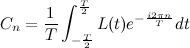
Consider the transition to the spectral representation in the form of a periodic function:
As is known, a periodic function satisfying the Dirichlet condition can be represented by a number of harmonic functions.

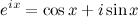
According to Euler’s formula, any expression can be represented as
 - the frequency of the first harmonic
 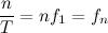 - the frequency of the nth harmonic
  - the circular frequency of the nth harmonic
  - the complex amplitude of the harmonic, where
  is the phase spectrum.
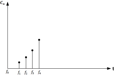
 The set of amplitudes of the harmonics of the Fourier series is called the amplitude spectrum, and the set of their phases is called the phase spectrum.
Spectrum example:
For a non-periodic function
 ,
,  then it
  is replaced by a continuously changing frequency => the sum is replaced by the integral.
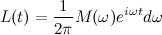
Direct Fourier Transform for a Non-Periodic Signal
Thus, the spectrum of a non-periodic function is represented by the sum of an infinite number of harmonic oscillations, whose frequencies are located infinitely close to each other.
Level quantization
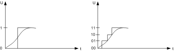
The number of quantization levels is determined by the formula

n - the number of bits
N - quantization level
The choice of the number of quantization levels of signals is based on a compromise approach that takes into account the need for a sufficiently accurate representation of the signal, which requires a large number of quantization levels, and on the other hand, the number of quantization levels to be less, so that the bit depth of the code is minimal.
On this I will end my article so as not to overload the reader with unnecessary information. Good luck in your endeavors!