 June 11, 2010 at 16:07
X.25 Switched Packet Networks
Dear Khabrovites, I want to tell you about packet switching networks built on the basis of the ITU-T X.25 data transfer protocol. I was fortunate enough to be involved in the maintenance and development of one X.25 corporate network for several years.
I do not intend to tell you specifically about the X.25 protocol, it can be found in accessible sources , I want to share my experience - what was it? why was this necessary? which of these may come in handy in the future? I write from memory, so I can be a little mistaken or confused about what is an element of the standard and what is part of the implementation
The X.25 protocol was developed to replace the ISDN protocol, which has significant drawbacks for data transmission (lack of statistical multiplexing). The first edition of the standard was approved in 1976. The protocol was based on the following main ideas:
- Transmission control between two network nodes
- Transmission control between end users
- Routing at the moment of connection establishment
- Packet switching on the established route
Many sources say that X.25 is a link layer protocol. This is not true. X.25 was created before the development of the seven-level OSI model. It is “written” to the link layer only because of the widely used encapsulation of the IP protocol in X.25. In fact, the protocol has all the signs of a network layer (routing between networks) and provides control of transmission between end users, i.e. goes transport level.
The main advantage of the protocol is high efficiency in networks built on communication channels with a high level of errors. The main disadvantages are limited performance, not being able to transmit real time data.
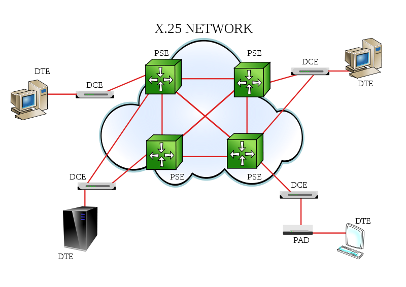
All X.25 network subscribers are divided into synchronous and asynchronous. Synchronous ones have built-in X.25 interfaces, and asynchronous ones use a device called PAD (Packet Assembler-Disassembler) to transfer data. PAD receives asynchronous streams from its ports and transmits them in a dial-up connection through the X.25 interface.
The core of the network is packet switches. They are interconnected by synchronous communication channels (mainly X.21 via synchronous modems via PM channels or radio channels). Synchronous network subscribers are connected directly to the packet switches. PADs are also connected to the switches.
The network uses X.121 addressing. It is somewhat reminiscent of IP addressing, but without dots and with a decimal mask. The mask is never explicitly specified, just the address length can vary from 10 to 15 decimal characters.
X.121 address looks like:
DDDDNNNPPPP [SSSSS]
where
DDDD - DNIC (Network number, analog of the autonomous system in IP)
NNN - Node (Node number)
PPPP - Port (Port number)
SSSSS - Subadress
Each subnet switch has its own routing table. The table indicates which port to route the connection to at the specified address. The sender address is usually not parsed.
An important point is that routing occurs at the time of establishing a logical connection (SVC), after the connection is established, only switching occurs. For this, logical channels (LCIs) are created on each port. The number of available LCIs on an interface limits the available number of logical connections through it.
If a failure occurs on the route of the established connection, then after a timeout and retries the subscribers will re-establish the connection.
The network I had to deal with was initially used for the operation of asynchronous terminals, which via zmodem transferred files to a file switch (“turntable”). Later, synchronous terminals appeared, exchanging information with the server and IP routers. Everything worked very slowly and very reliably. The speed on the main channels of the PM was no higher than 19200, and in the outback there were 2400 “for happiness”, which did not interfere with the transmission of data.
Later, the FR channels that were used for X.25 over FR began to appear. When high-quality IP channels appeared, they gradually began to implement XOT (X.25 over IP).
An important point - both technologies involve the tunneling of X.25 through non-native protocols for it. Sometimes it is convenient to “terminate” the X.25 protocol on the interface to which it comes through the tunnel. The protocol does not provide for this, protocol termination is possible only on interfaces with pure X.25 (over LAP-B), and tunneling can only be used inside the network for switching between nodes.

The network I worked with was built on the equipment of the British company Case Communications . This company often changed owners and names, at one time it was called Cray Communications. They started with packet switches, they also had Ethernet products, routers. The division that produced the routers was bought by Intel, as a result of which there were quite well-known models of Intel Express Router 9100 and others like it. The company is currently developing and manufacturing linux routers.
The Case Packet Switch range consisted of nodes (Packet Switch Exchange - PSE), X.25 / Frame-Relay Assembler-Disassembler - XFRAD switches, and PAD. The peculiarity of PSE was that it was possible to make trunk connections between them, which were not addressed like regular ports, but were used for communication between network nodes. The control system on the Sun platform with a graphical interface for X11 was supplied with the network.
The most advanced model was the modular PSE8525. This is a 13 unit chassis for a 19 "rack with 16 interface modules and a control module, up to 5 power supplies were installed in the chassis. The architecture of this gizmo deserves special attention.

The basis was a vertical backplane board. No active elements were found on it (!) - just a set of tires. Backplane divided the chassis into two parts - in the front of the board with controllers and processors, in the back - boards with interfaces, a total of 17 slots. In the first 16 slots, it was possible to install X.25 port cards or PAD cards. In the last slot is the manager board.
PAD boards were “half” (will be further) and were logically separate devices and were connected to the switch in which they stood by external cables.
All other boards consisted of two parts - the controller board and the processor board. The processor boards (UPM) were the same for all the boards, the X.25 port controller (SP-XIM) and the manager were different.

The system booted up in stages. After turning on the power from floppy disk A, the manager was loaded. After loading, he read the configuration from floppy disk B and loaded interface cards one at a time. PADs loaded on their own as soon as the power appeared. After loading all the boards, they could work independently, each of them could be rebooted separately. The manager in the system was needed only when changing the configuration or rebooting.
All boards could be removed and reinstalled on the go. There are cases when the chassis worked without a manager for more than a month. Compare this to pulling a supervisor out of the Cisco7600! ;)
The X.25 protocol played an excellent role in telecommunications and communications. At the time it was created, he solved the problem of efficient use of low-speed communication channels with a high level of transmission errors. The developers of X.25 equipment did not rely on speed, but on reliability and survivability of the solution, therefore this protocol is still alive in the banking sector.
The development of communication systems has led to the fact that the X.25 protocol has ceased to meet the requirements of modern applications for data transfer speed, and the presence of high-speed communication channels with a low level of error allows us to solve modern problems using the TCP / IP family of protocols.
The foundations laid down in the architecture of the protocol and X.25 networks illustrate a rational approach to solving the problem, and are excellent training material. Perhaps some of the ideas laid down in X.25 will come back but at higher levels. In particular, MPLS TE (Traffic Engineering) technology is somewhat similar to X.25 in terms of logical channel construction.
I recommend everyone who is going to become a specialist in the field of networks and communications to study the basics of the X.25 protocol, despite the fact that his knowledge is not required for work in many communications enterprises. When studying it, I recommend focusing not on how a particular function is implemented, but on the purpose for which it was included in the protocol.
I do not intend to tell you specifically about the X.25 protocol, it can be found in accessible sources , I want to share my experience - what was it? why was this necessary? which of these may come in handy in the future? I write from memory, so I can be a little mistaken or confused about what is an element of the standard and what is part of the implementation
X.25 Protocol
The X.25 protocol was developed to replace the ISDN protocol, which has significant drawbacks for data transmission (lack of statistical multiplexing). The first edition of the standard was approved in 1976. The protocol was based on the following main ideas:
- Transmission control between two network nodes
- Transmission control between end users
- Routing at the moment of connection establishment
- Packet switching on the established route
Many sources say that X.25 is a link layer protocol. This is not true. X.25 was created before the development of the seven-level OSI model. It is “written” to the link layer only because of the widely used encapsulation of the IP protocol in X.25. In fact, the protocol has all the signs of a network layer (routing between networks) and provides control of transmission between end users, i.e. goes transport level.
The main advantage of the protocol is high efficiency in networks built on communication channels with a high level of errors. The main disadvantages are limited performance, not being able to transmit real time data.
X.25 network
All X.25 network subscribers are divided into synchronous and asynchronous. Synchronous ones have built-in X.25 interfaces, and asynchronous ones use a device called PAD (Packet Assembler-Disassembler) to transfer data. PAD receives asynchronous streams from its ports and transmits them in a dial-up connection through the X.25 interface.
The core of the network is packet switches. They are interconnected by synchronous communication channels (mainly X.21 via synchronous modems via PM channels or radio channels). Synchronous network subscribers are connected directly to the packet switches. PADs are also connected to the switches.
The network uses X.121 addressing. It is somewhat reminiscent of IP addressing, but without dots and with a decimal mask. The mask is never explicitly specified, just the address length can vary from 10 to 15 decimal characters.
X.121 address looks like:
DDDDNNNPPPP [SSSSS]
where
DDDD - DNIC (Network number, analog of the autonomous system in IP)
NNN - Node (Node number)
PPPP - Port (Port number)
SSSSS - Subadress
Each subnet switch has its own routing table. The table indicates which port to route the connection to at the specified address. The sender address is usually not parsed.
An important point is that routing occurs at the time of establishing a logical connection (SVC), after the connection is established, only switching occurs. For this, logical channels (LCIs) are created on each port. The number of available LCIs on an interface limits the available number of logical connections through it.
If a failure occurs on the route of the established connection, then after a timeout and retries the subscribers will re-establish the connection.
The network I had to deal with was initially used for the operation of asynchronous terminals, which via zmodem transferred files to a file switch (“turntable”). Later, synchronous terminals appeared, exchanging information with the server and IP routers. Everything worked very slowly and very reliably. The speed on the main channels of the PM was no higher than 19200, and in the outback there were 2400 “for happiness”, which did not interfere with the transmission of data.
Later, the FR channels that were used for X.25 over FR began to appear. When high-quality IP channels appeared, they gradually began to implement XOT (X.25 over IP).
An important point - both technologies involve the tunneling of X.25 through non-native protocols for it. Sometimes it is convenient to “terminate” the X.25 protocol on the interface to which it comes through the tunnel. The protocol does not provide for this, protocol termination is possible only on interfaces with pure X.25 (over LAP-B), and tunneling can only be used inside the network for switching between nodes.
Case communications
The network I worked with was built on the equipment of the British company Case Communications . This company often changed owners and names, at one time it was called Cray Communications. They started with packet switches, they also had Ethernet products, routers. The division that produced the routers was bought by Intel, as a result of which there were quite well-known models of Intel Express Router 9100 and others like it. The company is currently developing and manufacturing linux routers.
The Case Packet Switch range consisted of nodes (Packet Switch Exchange - PSE), X.25 / Frame-Relay Assembler-Disassembler - XFRAD switches, and PAD. The peculiarity of PSE was that it was possible to make trunk connections between them, which were not addressed like regular ports, but were used for communication between network nodes. The control system on the Sun platform with a graphical interface for X11 was supplied with the network.
The most advanced model was the modular PSE8525. This is a 13 unit chassis for a 19 "rack with 16 interface modules and a control module, up to 5 power supplies were installed in the chassis. The architecture of this gizmo deserves special attention.
The basis was a vertical backplane board. No active elements were found on it (!) - just a set of tires. Backplane divided the chassis into two parts - in the front of the board with controllers and processors, in the back - boards with interfaces, a total of 17 slots. In the first 16 slots, it was possible to install X.25 port cards or PAD cards. In the last slot is the manager board.
PAD boards were “half” (will be further) and were logically separate devices and were connected to the switch in which they stood by external cables.
All other boards consisted of two parts - the controller board and the processor board. The processor boards (UPM) were the same for all the boards, the X.25 port controller (SP-XIM) and the manager were different.
The system booted up in stages. After turning on the power from floppy disk A, the manager was loaded. After loading, he read the configuration from floppy disk B and loaded interface cards one at a time. PADs loaded on their own as soon as the power appeared. After loading all the boards, they could work independently, each of them could be rebooted separately. The manager in the system was needed only when changing the configuration or rebooting.
All boards could be removed and reinstalled on the go. There are cases when the chassis worked without a manager for more than a month. Compare this to pulling a supervisor out of the Cisco7600! ;)
Conclusion
The X.25 protocol played an excellent role in telecommunications and communications. At the time it was created, he solved the problem of efficient use of low-speed communication channels with a high level of transmission errors. The developers of X.25 equipment did not rely on speed, but on reliability and survivability of the solution, therefore this protocol is still alive in the banking sector.
The development of communication systems has led to the fact that the X.25 protocol has ceased to meet the requirements of modern applications for data transfer speed, and the presence of high-speed communication channels with a low level of error allows us to solve modern problems using the TCP / IP family of protocols.
The foundations laid down in the architecture of the protocol and X.25 networks illustrate a rational approach to solving the problem, and are excellent training material. Perhaps some of the ideas laid down in X.25 will come back but at higher levels. In particular, MPLS TE (Traffic Engineering) technology is somewhat similar to X.25 in terms of logical channel construction.
I recommend everyone who is going to become a specialist in the field of networks and communications to study the basics of the X.25 protocol, despite the fact that his knowledge is not required for work in many communications enterprises. When studying it, I recommend focusing not on how a particular function is implemented, but on the purpose for which it was included in the protocol.









