Leave me alone with your batteries: the main thing for a good electric car is a lightweight engine
- Transfer
The design of the author represents a new word in the development of electric motors.
In the first decade of the 20th century, 38% of all cars in the US worked on electricity - and this percentage dropped to almost zero with an increase in the dominance of ICE in the 1920s. Today’s desire to conserve energy and reduce harmful emissions has breathed new life into electric vehicles, but their high cost and limited mileage are holding back sales.
Most attempts to solve these problems are related to battery improvements. Of course, improving energy storage systems, whether batteries or fuel cells, should remain part of any strategy for improving electric cars, but there is potential for improvement in another fundamental component of the machines: in the engine. For the past four years, we have been working on a new concept for a traction motor used in electric vehicles and trucks. Our latest development greatly improves efficiency compared to conventional models - enough to make electric cars more practical and affordable.
Last year we proved the performance of our engine in comprehensive laboratory tests, and although it’s still far from being placed in a car, we have every reason to believe that it will show itself just as well there. Our engine will be able to increase the mileage of modern electric vehicles, even if we do not make any progress in battery technology.
To understand the complexity of our task, it is necessary to recall the basics of an electric motor (EM) circuit. Compared with ICE, EM is simpler, they have only a few critical components. Mechanics require a housing. It is called a stator because it does not move. Requires a rotor that rotates the shaft and creates torque. For the motor to work, the stator and the rotor must interact with the help of magnetism, turning electrical energy into mechanical energy.
Motor concepts differ precisely in the field of magnetic interfaces. In DC collector motors, current flows through brushes sliding along the collector node. The current flows through the collector and transfers energy to the winding on the rotor. Winding is repelled by permanent magnets or stator electromagnets. The brushes, sliding along the collector, periodically change the direction of the current, and the magnets of the rotor and stator repel each other again and again, causing the rotor to rotate. In other words, the rotational movement is provided by a varying magnetic field produced by the collector, connecting the coils to the current source and cyclically changing the direction of the current when the rotor turns. However, this technology limits torque and suffers from wear; It is no longer used in traction EMs.
In modern electric vehicles using alternating current from the inverter. Here a dynamic rotating magnetic field is created in the stator, and not in the rotor. This allows us to simplify the rotor circuit, which is usually more complex than the stator, which facilitates all the tasks associated with the development of EM.
AC motors are of two types: asynchronous and synchronous. We will focus on synchronous, as they usually work better and more efficiently.
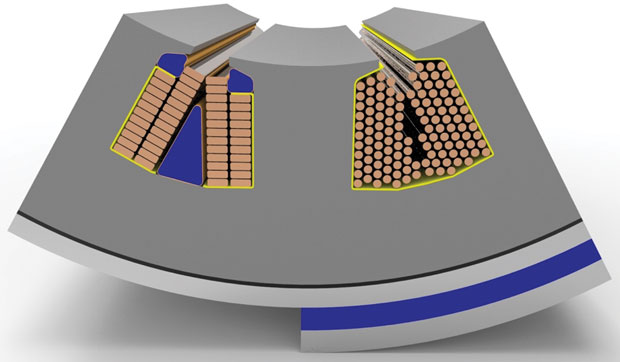
The advanced cooling system conducts the fluid directly through the coil (left) and not through the motor casing (right)
Synchronous motors also come in two forms. The more popular is the permanent-magnet synchronous machine (PMSM), which uses permanent magnets built into the rotor. To make it rotate, a rotating magnetic field is organized in the stator. This field is obtained due to the stator winding connected to the AC source. During operation, the poles of the permanent magnets of the rotor are captured by the rotating magnetic field of the stator, which causes the rotor to rotate.
Such a scheme, used in the Chevrolet Volt and Bolt, in the BMW i3, in the Nissan Leaf and many other cars, can reach a peak efficiency of 97%. Permanent magnets are usually made from rare earths; vivid examples are very powerful neodymium magnets, developed in 1982 by General Motors and Sumitomo.
The open-pole synchronous motors [Salient-pole synchronous machines, SPSM)] use inside the rotor not permanent, but electromagnets. The poles are coils in the form of pipes, directed outwards, like wheel spokes. These electromagnets in the rotor are powered by a constant current source connected to them through slip rings. Slip rings, unlike the collector, do not change the direction of the current. The north and south poles of the rotor are static, and the brushes do not wear out so quickly. As in the case of PMSM, the rotor rotates due to the rotation of the magnetic field of the stator.
Because of the need to feed the rotor electromagnets through the slip rings, these motors usually have a slightly lower peak efficiency in the range from 94 to 96%. The advantage over PMSM is the rotor field adjustability, which allows the rotor to more effectively generate torque at high speeds. The total efficiency when used to disperse the machine increases. The only manufacturer of such engines in serial cars is Renault with its models Zoe, Fluence and Kangoo.
Electric vehicles must be built with not only efficient, but also lightweight components. The most obvious way to improve the power to weight ratio is to reduce the size of the motor. However, such a machine will produce less torque for the same rotational speed. Therefore, to get more energy, it is necessary to rotate the motor at higher speeds. Today's electric cars run at 12,000 rpm; in the next generation there will be motors operating at 20,000 rpm; work is already under way on engines operating at a speed of 30,000 rpm. The problem is that the higher the speed, the harder the reduction gear turns out - the speed of rotation of the motor is too much higher than the speed of rotation of the wheels. From the complexity of the gearbox followed by large energy loss.
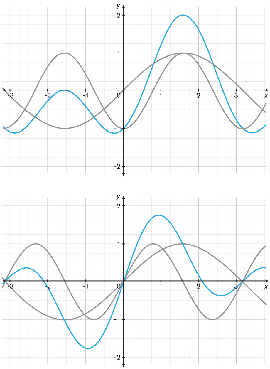
Ideal storm: in the author's version (above), the Lorentz force and the displaced inductance (gray) are summed to the maximum total force (blue) equal to 2. In a conventional motor (below) the sum of two forces - the Lorentz forces and magnetic resistance (gray) give a total force ( blue), reaching a peak of only 1.76, with a run-out angle of the rotor at 0.94 rad. The difference in this example is 14%. The
second approach to improving the power-to-weight ratio is to increase the strength of the magnetic field, which increases the torque. This is the meaning of adding an iron core to the coil - although this increases the weight, it simultaneously increases the magnetic flux density by two orders of magnitude. Consequently, almost all modern EMs use iron cores in the stator and rotor.
However, there is a minus. When the field strength increases to a certain limit, the iron loses the possibility of increasing the flux density. This saturation can be slightly affected by adding additives and changing the process of making iron, but the most effective materials are limited to 1.5 V * s / m 2 (volts per second per square meter, or tesla, T). Only very expensive and rare vacuum iron-cobalt materials can reach magnetic flux densities of 2 T or more.
And finally, the third standard way to increase the torque - field amplification through the amplification of the current passing through the coils. Again, there are limitations. Increase the current and the resistance losses increase, the efficiency will decrease and heat will appear that can damage the motor. For wires, you can use a metal that is better conductive than copper. Silver wires also happen, but their use in such a device would be absurdly expensive.
The only practical way to increase current is to control heat. Advanced cooling solutions conduct the fluid right next to the coils, and not further away from them, outside the stator.
All these steps help to improve the ratio of weight to power. In racing electric cars, where the cost does not matter, the motors can reach 0.15 kg per kilowatt, which is comparable to the best ICE from Formula 1.
We with the students developed and created such high-performance electric motors for the car that participated in the student Formula three years ago. We created motors in our laboratory.at the Electrotechnical Institute of Karlsruhe Institute of Technology. Every year the team created a new car with an improved motor, gearbox and power electronics. In the car, four engines, one for each wheel. Each is only 8 cm in diameter, 12 cm in length and 4.1 kg in weight, and produces 30 kW on a constant basis and 50 kW at the peak. In 2016, our team won the world championship .
So it really can be done if the cost does not bother you. The main question is whether it is possible to use such efficiency-improving technologies in mass production, in a car that you could buy? We have created such a motor, so the answer to the question is positive.
We started with a simple idea. Electric motors work well both in the role of motors and in the role of generators, although such symmetry is not particularly needed for electric vehicles. A car needs a motor that works better as a motor than as a generator — the latter is used only to charge the batteries during regenerative braking.
To understand this idea, consider the operation of the PMSM motor. In such a motor movement creates two forces. Firstly, the force arising from the permanent magnets in the rotor. When current flows through the copper coils of the stator, they create a magnetic field. Over time, the current passes from one coil to another and causes the magnetic field to rotate. The rotating field of the stator attracts the permanent magnets of the rotor, and it starts moving. This principle is based on the Lorentz force, which affects the motion of a charged particle in a magnetic field.
But modern EMs receive some of the energy from the magnetic resistance - the force that attracts the block of iron to the magnet. The rotating field of the stator attracts both permanent magnets and rotor iron. The Lorentz force and the magnetic resistance work side by side, and - depending on the motor circuit - are approximately equal to each other. Both forces are approximately zero when the magnetic fields of the rotor and stator are equalized. With an increase in the angle between them, the motor produces mechanical energy.
In a synchronous motor, the stator and rotor fields work together without delays existing in asynchronous machines. The stator field is at a certain angle to the rotor field, which can be adjusted during operation to achieve the greatest efficiency. The optimal angle to create the torque at a given current can be calculated in advance. It then adjusts, as the current changes, to a power electronic system that provides alternating current to the stator winding.
But here's the problem: when the stator field moves relative to the rotor position, the Lorentz force and the magnetic resistance either increase or decrease. The Lorentz force increases in a sine wave that reaches a peak 90 degrees from the reference point (from the point at which the stator and rotor fields are aligned). The force of manitally resistance cyclically changes twice as fast, therefore it reaches a peak at 45 degrees.
Since the forces reach a maximum at different points, the maximum motor power is less than the sum of its parts. Suppose that a certain motor at a certain moment of work turns out that the optimum angle for the maximum of the total force will be 54 degrees. In this case, this peak will be 14% less than the total peaks of the two forces. This is the best possible compromise of this scheme.
If we could alter this motor so that the two forces reached a maximum at one point in the cycle, the power of the motor would increase by 14% completely free of charge. You would lose only the performance of the generator. But we, as will be shown later, have found a way to restore this ability as well, so that the motor better restores energy during braking.
Developing a perfectly leveling motor field is not easy. The problem is the combination of PMSM and SPSM into a new hybrid scheme. The result is a hybrid synchronous motor with an offset axis of magnetic resistance. In fact, this motor uses both wires and permanent magnets to create a magnetic field in the rotor.
Others tried to work in this direction, and then dropped this idea - but they wanted to use permanent magnets only to amplify the electromagnetic field. Our innovation is to use magnets only to give an accurate shape to the field in order to optimally align two forces - the Lorentz force and the magnetic resistance force.
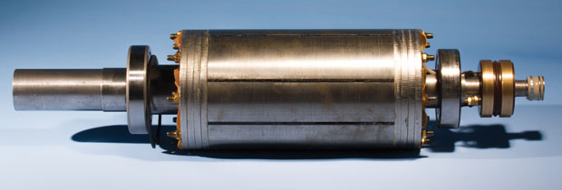
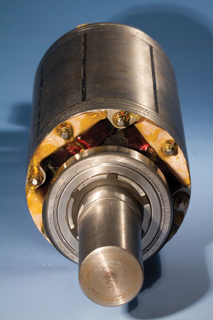
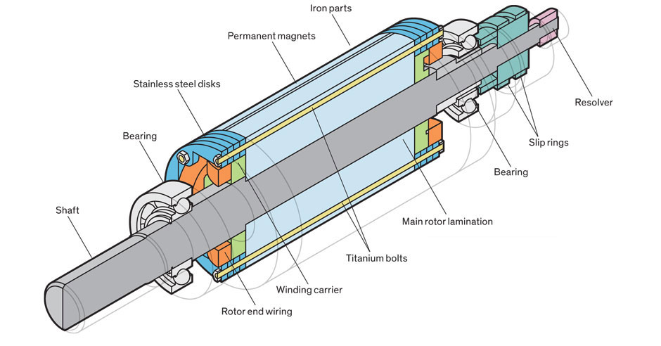
The main problem in the development was the search for such a rotor design that could change the shape of the field, while remaining strong enough to rotate at high speeds without breaking. At the center of our scheme is the multilayer structure of a rotor carrying copper winding on an iron core. We glued permanent magnets to the poles of the core; additional spikes impede their departure. In order to keep everything in place, we used strong and lightweight titanium pins, passed through the electromagnetic poles of the rotor, pulled by nuts to the stainless steel rings.
We also found a way around the disadvantage of the original motor, reducing the torque while the generator is running. Now we can change the direction of the field in the rotor so that the generation during regenerative braking works as effectively as the motor mode.
We achieved this by changing the direction of the current in the winding of the rotor while operating in the generator mode. It works as follows. Imagine the original appearance of the rotor. If you go around its perimeter, you will find a specific sequence of the north and south poles of electromagnetic (E) and permanent magnetic (P) sources: NE, NP, SE, SP. This sequence is repeated as many times as there are pairs of poles in the motor. Changing the direction of the current in the winding, we change the orientation of the electromagnetic poles, and only them, as a result, the sequence turns into SE, NP, NE, SP.
After studying these two sequences, you will see that the second is similar to the first, going backwards. This means that the rotor can be used in the motor mode (the first sequence) or in the generator mode (the second), when the current in the rotor changes direction to the opposite. Thus, our machine operates more efficiently than conventional motors, both as a motor and as a generator. On our prototype, changing the direction of the current takes no more than 70 ms, which is fast enough for cars.
Last year, we built a prototype of a motor on a workbench and subjected it to thorough checks. The results are clear: with the same power electronics, stator parameters and other limitations of a conventional motor, the machine is capable of delivering almost 6% more torque and 2% more efficiency at peak. The results are even better in the driving cycle: it needs 4.4% less energy. This means that a car driving 100 km on a single charge would drive 104.4 km with this motor. We get extra kilometers almost for free, because in our scheme there are only a few extra parts, which are noticeably less expensive than extra batteries.
We contacted several equipment manufacturers, and they found our concept interesting, although it would take a long time before you see one of these asymmetric engines in a production car. But having appeared, as a result, it will become a new standard, since the extraction of all possible benefits from the energy you have is in priority both for the automakers and for our entire society.