July 20, 2019 at 21:38
Experience in using a GSM module in home automation
It is cold at the cottage, and you want to turn on the heater a few hours before your arrival, or you are worried about the possibility of an emergency shutdown of the heating system of a country house in your absence. All these problems can be solved using the GSM module, which can send and receive SMS messages and respond to them, turning the necessary load on and off. In theory, everything is simple, in practice, on the way to implementing such a device, there are many pitfalls.
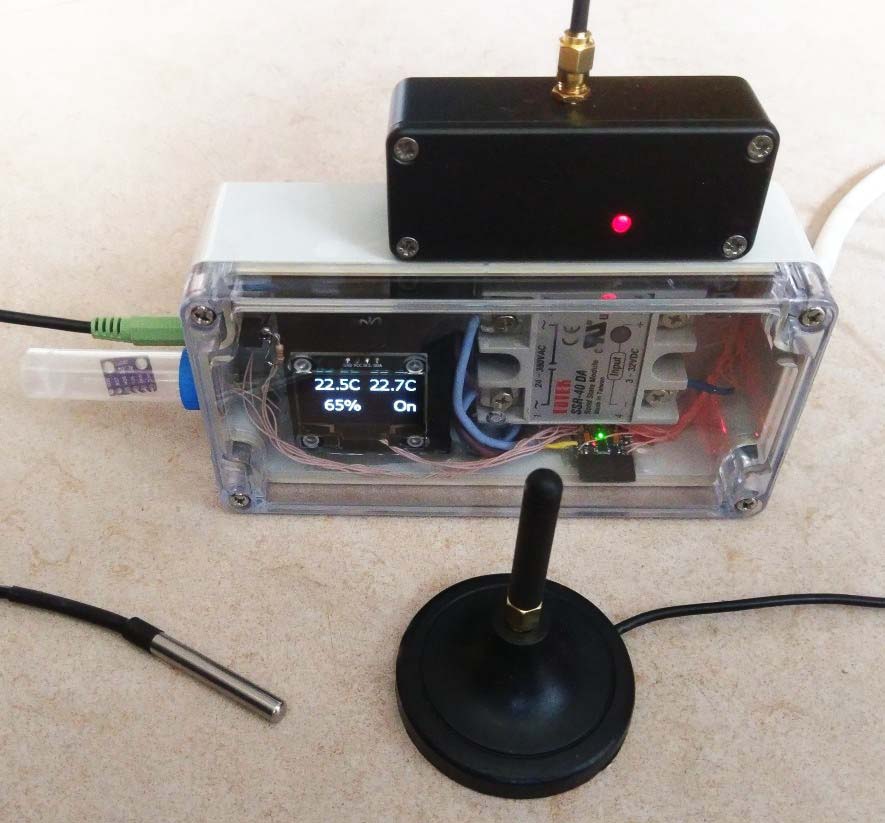
My plan was to create a simple and cheap device equipped with two temperature sensors, a humidity sensor, a GSM module, as well as a solid state relay and a socket for connecting the load. What happened in the end can be seen in the photo. The BME280 climate sensor was chosen as a temperature and humidity sensor; its pressure channel is not used. In the photo, you can see it under the transparent cap to the left of the main module. This arrangement reduces the effect of heat generation inside the housing on the sensor readings. As a cap, a Chinese plastic test tube with two ventilation holes is used. The second temperature sensor is remote, made on the DS18B20. It is located inside a metal probe, connected to the housing with a cable through a regular audio jack for headphones. The probe is designed to measure the temperature of the heating system directly. The main body volume is occupied by a solid-state relay (I chose a more powerful one) and a converter from 220V to 5V to power the circuit. The socket for connecting the load is mounted on the rear side of the case, in the photo it is not visible. An OLED display based on the SH1106 controller displays sensor readings and also shows whether the load is on. To control the entire system, the Arduino Pro Mini module is used in version 3.3V 8MHz. I am not a big fan of this platform, but the abundance of libraries, including carefully drunk by the author, makes her the best choice when you need to quickly do something simple. The socket for connecting the load is mounted on the rear side of the case, in the photo it is not visible. An OLED display based on the SH1106 controller displays sensor readings and also shows whether the load is on. To control the entire system, the Arduino Pro Mini module is used in version 3.3V 8MHz. I am not a big fan of this platform, but the abundance of libraries, including carefully drunk by the author, makes her the best choice when you need to quickly do something simple. The socket for connecting the load is mounted on the rear side of the case, in the photo it is not visible. An OLED display based on the SH1106 controller displays sensor readings and also shows whether the load is on. To control the entire system, the Arduino Pro Mini module is used in version 3.3V 8MHz. I am not a big fan of this platform, but the abundance of libraries, including carefully drunk by the author, makes her the best choice when you need to quickly do something simple.
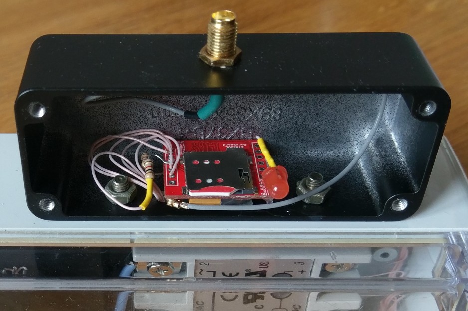
The SIM800L GSM module is housed in a separate metal housing to reduce the interference it creates to the rest of the circuit. As practice has shown, the interference from this is not reduced much. And radically they are reduced by an external antenna connected by a shielded cable to the coaxial connector, in the photo above it is in the foreground. But we will talk about this in more detail later.
A lot of articles have been written about the use of GSM modules, including on the hub, so I will avoid repetitions and talk about what I have not seen in publications on this topic, namely how to make a reliable device based on this module.
In the garages, where I often visit, recently put up a barrier at the entrance, which opens when you call a certain number. Apparently, it is made on a similar GSM module. I was surprised how difficult it is to get through this number to open it. Now I know many reasons for this. This knowledge cost me several months of experiments and an impressive amount of money spent on them. I hope that now this knowledge will serve someone else. Consider what it is important to pay attention to, moving from obvious hardware problems to less obvious software ones.
It seemed obvious to me that the SIM card is inserted with a beveled corner forward. For a week I have been trying to understand why the module does not want to register on the network, simultaneously mastering commands in the terminal. As a result, on some English-language forum, I found a mention that you need to insert it with a beveled corner back. It is strange that it is generally inserted both this way and that.
The power requirements for the GSM module are quite specific. It is made on the basis of a microchip designed for push-button mobile phones and is designed to be powered directly from a lithium battery. Therefore, 5V is a lot for him, and 3.3V is not enough. In addition, in the transmission mode at maximum power, it is able to consume current up to 2A. If the power source is not able to provide the required current, the GSM module may reboot when trying to register on the network and continue to reboot in an endless cycle. Peak consumption periods usually last less than a second, so it is tempting to use a low-current stabilizer with energy storage for periods of peak load. As such a drive, you can use a lithium battery. It’s important to ensure that you can turn it off and it’s important to remember to use it otherwise, disconnecting the device from the network will result in a deep discharge of the battery and its permanent damage. Another option is to replace the battery with an ionistor (supercapacitor). He is not afraid of deep discharge. But he also has problems with reliability. One cell of the ionistor is usually rated for voltage from 2.5 to 3V. Ionistors designed for higher voltage consist of several cells (usually 2). In this case, however, the voltage imbalance in the cells may result in cell breakdown. Such an imbalance is easily obtained due to the difference in cell capacitance or the difference in leakage current. The internal resistance parameter of the ionistor should also be considered. Ionistors with high internal resistance at high currents are useless, and ionistors with low resistance are no cheaper than the battery. After that, As my ionistor died suddenly due to an imbalance of cells, I just applied a converter from 220V to 5V of sufficient power. In order to lower the voltage to the desired GSM module, I put a regular silicon diode between the converter and the module. On such a diode, 0.7V usually drops, so the module gets the necessary 4.3V. After the diode, it is useful to place a large-capacity electrolytic capacitor. It will smooth out voltage dips when the transmitter is suddenly turned on.
Even after I provided the GSM module with the required power, the reboot symptom periodically appeared, but this time the Arduino rebooted. Observing its power using an oscilloscope showed that power is not necessary here. Apparently, the transmitter created the module, since the problem arose more often the worse the reception conditions of the base station signal. Such a radical effect of interference from the transmitting antenna is quite explainable if we recall that the transmitter of the module is capable of delivering 2 watts to the antenna. Such power can boil a milliliter of water in 5 minutes or heat your ear a few degrees. To combat this problem, various methods have been tried. First, I connected an external antenna, which was located outside the case and connected to the module with a short coaxial cable. However, this did not give the expected effect. Then I placed the module in a separate metal case, to which the antenna was attached from the outside. It got better, but not much. Radically improved the situation only the removal of the antenna at a certain distance from the device due to its connection with a coaxial cable of sufficient length.
Why this happens is easy to understand from physical considerations. A typical antenna is a quarter-wave pin, that is, half of the dipole antenna. But, to create an electric field, half of the dipole is not enough, you need the second half, then an electric field will appear between the negatively and positively charged elements of the antenna. For a regular whip antenna, the other half is either the earth’s surface, or the instrument’s body, or special conductive 'balances'. But for marketers, all this is too complicated, so we usually only sell half of the normal antenna. How does she work? Very simple - the other half is the cable that the antenna is connected to. The fact that it is shielded does not change anything. The outer surface of its braid plays the role of the second half of the dipole antenna. In this case, interference is easily induced to the wires passing in the neighborhood, despite the fact that the cable would seem to be shielded. Well, if there is no cable, for example, we hid the module in a metal screen, from which the antenna sticks out? If the screen is large (compared to the wavelength), then it works like the second half of the emitter, and if it is small, then the other wires that are connected to this module emit, it does not matter which ones. The following figure illustrates the above (the pros and cons are shown for clarity, in reality, the charge of the antenna elements changes sign with the carrier frequency). like the second half of the emitter, and if it’s small, then the other wires that are connected to this module emit, it does not matter which one. The following figure illustrates the above (the pros and cons are shown for clarity, in reality, the charge of the antenna elements changes sign with the carrier frequency). like the second half of the emitter, and if it’s small, then the other wires that are connected to this module emit, it does not matter which one. The following figure illustrates the above (the pros and cons are shown for clarity, in reality, the charge of the antenna elements changes sign with the carrier frequency).

The 'right' antenna is shown on the left; its lead-in cable does not emit interference. The middle image shows the antenna you usually buy. Here, the lead-in cable is part of the emitter and interferes with wires passing nearby. The situation on the right shows when the signal source is hidden in a compact shielded enclosure. Here, any wires brought to such a housing are part of the emitter.
The moral is that the only reliable way to protect yourself from the interference caused by the transmitting antenna is to take it away from the rest of the electronics by connecting it with a coaxial cable of sufficient length. How long is sufficient? It is natural to measure the distance with the wavelength, in this case it is a maximum of 30 cm. This is the minimum distance by which the antenna should be assigned, but the further the better.
In simple AVR microcontrollers, which everyone usually uses, there is only one hardware serial port, and it is used to download the program. Therefore, software implementation of the serial port is a very popular solution. I’m going to prove a statement that many would find unexpected - for managing the GSM module, the software implementation of the serial port is unsuitable at all.
The essence of the problem is that the software implementation of the serial port prohibits interruptions for the entire time the next character is transmitted or received. It would seem that this is bad, as many do. For example, the implementation of the 1-Wire protocol for reading Dallas Semiconductor thermometers also prohibits interruptions during the transmission of one bit, that is, 65 microseconds. This, of course, is not too good either. If the system has other interrupt handlers, they will not be able to provide an interrupt response time less than these 65 microseconds. If an interrupt request arrives when they are denied, it will only be processed after the interrupt is resolved again. For example, a hardware serial port uses interrupts to put the next received character in the receiver buffer. If the next character comes, until the interrupt from the previous one is processed, it will be lost. This means that the hardware serial port will not be able to operate at a speed greater than 115200 bits per second. In the case of software implementation of the serial port, everything is worse. For its operation, it is necessary that the response time to an interrupt is less than the transmission time of one bit. This limits us to a speed of 9600 bits per second.
A more serious problem is that the serial port software itself prohibits interrupts. Moreover, the time for which it prohibits them (the time of transmission or reception of one character) is always about 10 times longer than the maximum interrupt processing time required for the correct operation of the receiver of the same software serial port. That is, it always interferes with itself to such an extent that at the same time it cannot receive and send data. Of course, in most cases this is not required. In most, but not in our case with the GSM module. He can, unexpectedly for us, on his own initiative, begin to transfer data (for example, when receiving an SMS message). And in the case of using a software implementation of the serial port, this can easily lead to a failure of the communication protocol with the module. Therefore, I just applied the same hardware serial port for both Arduino programming and communication with the GSM module. Inconvenient of course, but this is the only way to make a reliable device.
An asynchronous protocol is a protocol in which one side of the exchange can begin to transmit information unexpectedly to the other side, that is, without any synchronization with its messages. This is exactly the communication protocol with the GSM module. It regularly responds to requests from the Arduino, but it may also begin to transmit something of its own, for example, to inform about the received SMS message. And this creates a real problem, since none of the libraries I know for working with the module for Arduino take protocol asynchrony into account at all. Imagine that Arduino sent a command to the module, and the module at the same time transmitted information about the received SMS message. This information will be accepted instead of responding to the command. As a result, the library will return an error as a response to the command (in the best case, everything will 'hang' in the worst),
This is easy to fix - you just need to write your own, asynchronous protocol handler. An asynchronous handler makes only the necessary minimum requirements for module responses to its commands. As a result, the module answers either OK or ERROR to each command. And that’s all it takes to fix the answer. All other lines that come from the module are processed regardless of whether they came in response to a command or on their own. The meaning of these lines can always be determined by their beginning. If the line starts with + CSQ, then it contains information about the signal quality. If it starts + CMT, then this is information about the received SMS, and it contains the address of the sender. The first line is sent as part of the response to the AT + CSQ command, and the second module is sent on its own initiative, but for us this difference is absolutely insignificant. The module sends received SMS messages directly to the serial port. This avoids reading them from memory and subsequent deletion. In order for us to recognize SMS messages in the general message flow from the module, they must begin with the # symbol, otherwise the message is ignored.
A library created by the author that implements the above approach is located here .
To receive lines starting with a certain sequence of characters, the client creates a special object - a trap. He can create any number of such traps. The lines received from the module, other than OK, ERROR, which did not fall into any of the traps, are simply ignored. Since such an architecture does not require a complete analysis of module responses to many different types of commands, the library code is many times more compact than any of the libraries I know.
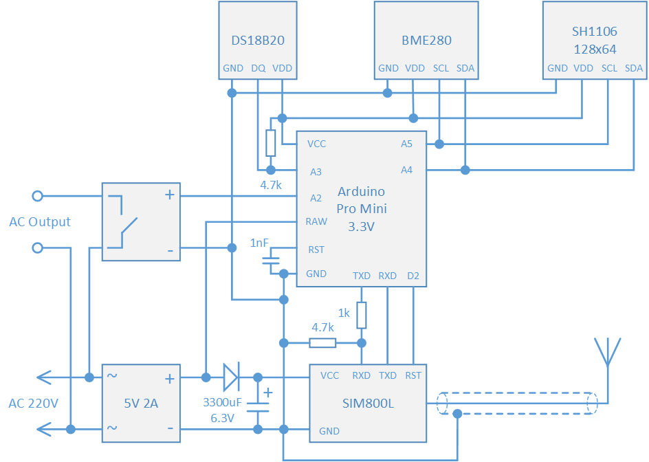
The result is a device that works reliably in an area with poor coverage, even better than the average phone. Below is a complete outline of it.
For those interested, there is a link to the github where you will find the source code of the project and a description of the commands that can be sent to the device in SMS messages.
github.com/olegv142/GsmMon
My plan was to create a simple and cheap device equipped with two temperature sensors, a humidity sensor, a GSM module, as well as a solid state relay and a socket for connecting the load. What happened in the end can be seen in the photo. The BME280 climate sensor was chosen as a temperature and humidity sensor; its pressure channel is not used. In the photo, you can see it under the transparent cap to the left of the main module. This arrangement reduces the effect of heat generation inside the housing on the sensor readings. As a cap, a Chinese plastic test tube with two ventilation holes is used. The second temperature sensor is remote, made on the DS18B20. It is located inside a metal probe, connected to the housing with a cable through a regular audio jack for headphones. The probe is designed to measure the temperature of the heating system directly. The main body volume is occupied by a solid-state relay (I chose a more powerful one) and a converter from 220V to 5V to power the circuit. The socket for connecting the load is mounted on the rear side of the case, in the photo it is not visible. An OLED display based on the SH1106 controller displays sensor readings and also shows whether the load is on. To control the entire system, the Arduino Pro Mini module is used in version 3.3V 8MHz. I am not a big fan of this platform, but the abundance of libraries, including carefully drunk by the author, makes her the best choice when you need to quickly do something simple. The socket for connecting the load is mounted on the rear side of the case, in the photo it is not visible. An OLED display based on the SH1106 controller displays sensor readings and also shows whether the load is on. To control the entire system, the Arduino Pro Mini module is used in version 3.3V 8MHz. I am not a big fan of this platform, but the abundance of libraries, including carefully drunk by the author, makes her the best choice when you need to quickly do something simple. The socket for connecting the load is mounted on the rear side of the case, in the photo it is not visible. An OLED display based on the SH1106 controller displays sensor readings and also shows whether the load is on. To control the entire system, the Arduino Pro Mini module is used in version 3.3V 8MHz. I am not a big fan of this platform, but the abundance of libraries, including carefully drunk by the author, makes her the best choice when you need to quickly do something simple.
The SIM800L GSM module is housed in a separate metal housing to reduce the interference it creates to the rest of the circuit. As practice has shown, the interference from this is not reduced much. And radically they are reduced by an external antenna connected by a shielded cable to the coaxial connector, in the photo above it is in the foreground. But we will talk about this in more detail later.
A lot of articles have been written about the use of GSM modules, including on the hub, so I will avoid repetitions and talk about what I have not seen in publications on this topic, namely how to make a reliable device based on this module.
In the garages, where I often visit, recently put up a barrier at the entrance, which opens when you call a certain number. Apparently, it is made on a similar GSM module. I was surprised how difficult it is to get through this number to open it. Now I know many reasons for this. This knowledge cost me several months of experiments and an impressive amount of money spent on them. I hope that now this knowledge will serve someone else. Consider what it is important to pay attention to, moving from obvious hardware problems to less obvious software ones.
The first thing that is important to do correctly is to insert a SIM card.
It seemed obvious to me that the SIM card is inserted with a beveled corner forward. For a week I have been trying to understand why the module does not want to register on the network, simultaneously mastering commands in the terminal. As a result, on some English-language forum, I found a mention that you need to insert it with a beveled corner back. It is strange that it is generally inserted both this way and that.
To work well, you need to eat well.
The power requirements for the GSM module are quite specific. It is made on the basis of a microchip designed for push-button mobile phones and is designed to be powered directly from a lithium battery. Therefore, 5V is a lot for him, and 3.3V is not enough. In addition, in the transmission mode at maximum power, it is able to consume current up to 2A. If the power source is not able to provide the required current, the GSM module may reboot when trying to register on the network and continue to reboot in an endless cycle. Peak consumption periods usually last less than a second, so it is tempting to use a low-current stabilizer with energy storage for periods of peak load. As such a drive, you can use a lithium battery. It’s important to ensure that you can turn it off and it’s important to remember to use it otherwise, disconnecting the device from the network will result in a deep discharge of the battery and its permanent damage. Another option is to replace the battery with an ionistor (supercapacitor). He is not afraid of deep discharge. But he also has problems with reliability. One cell of the ionistor is usually rated for voltage from 2.5 to 3V. Ionistors designed for higher voltage consist of several cells (usually 2). In this case, however, the voltage imbalance in the cells may result in cell breakdown. Such an imbalance is easily obtained due to the difference in cell capacitance or the difference in leakage current. The internal resistance parameter of the ionistor should also be considered. Ionistors with high internal resistance at high currents are useless, and ionistors with low resistance are no cheaper than the battery. After that, As my ionistor died suddenly due to an imbalance of cells, I just applied a converter from 220V to 5V of sufficient power. In order to lower the voltage to the desired GSM module, I put a regular silicon diode between the converter and the module. On such a diode, 0.7V usually drops, so the module gets the necessary 4.3V. After the diode, it is useful to place a large-capacity electrolytic capacitor. It will smooth out voltage dips when the transmitter is suddenly turned on.
Keep away from the transmit antenna.
Even after I provided the GSM module with the required power, the reboot symptom periodically appeared, but this time the Arduino rebooted. Observing its power using an oscilloscope showed that power is not necessary here. Apparently, the transmitter created the module, since the problem arose more often the worse the reception conditions of the base station signal. Such a radical effect of interference from the transmitting antenna is quite explainable if we recall that the transmitter of the module is capable of delivering 2 watts to the antenna. Such power can boil a milliliter of water in 5 minutes or heat your ear a few degrees. To combat this problem, various methods have been tried. First, I connected an external antenna, which was located outside the case and connected to the module with a short coaxial cable. However, this did not give the expected effect. Then I placed the module in a separate metal case, to which the antenna was attached from the outside. It got better, but not much. Radically improved the situation only the removal of the antenna at a certain distance from the device due to its connection with a coaxial cable of sufficient length.
Why this happens is easy to understand from physical considerations. A typical antenna is a quarter-wave pin, that is, half of the dipole antenna. But, to create an electric field, half of the dipole is not enough, you need the second half, then an electric field will appear between the negatively and positively charged elements of the antenna. For a regular whip antenna, the other half is either the earth’s surface, or the instrument’s body, or special conductive 'balances'. But for marketers, all this is too complicated, so we usually only sell half of the normal antenna. How does she work? Very simple - the other half is the cable that the antenna is connected to. The fact that it is shielded does not change anything. The outer surface of its braid plays the role of the second half of the dipole antenna. In this case, interference is easily induced to the wires passing in the neighborhood, despite the fact that the cable would seem to be shielded. Well, if there is no cable, for example, we hid the module in a metal screen, from which the antenna sticks out? If the screen is large (compared to the wavelength), then it works like the second half of the emitter, and if it is small, then the other wires that are connected to this module emit, it does not matter which ones. The following figure illustrates the above (the pros and cons are shown for clarity, in reality, the charge of the antenna elements changes sign with the carrier frequency). like the second half of the emitter, and if it’s small, then the other wires that are connected to this module emit, it does not matter which one. The following figure illustrates the above (the pros and cons are shown for clarity, in reality, the charge of the antenna elements changes sign with the carrier frequency). like the second half of the emitter, and if it’s small, then the other wires that are connected to this module emit, it does not matter which one. The following figure illustrates the above (the pros and cons are shown for clarity, in reality, the charge of the antenna elements changes sign with the carrier frequency).
The 'right' antenna is shown on the left; its lead-in cable does not emit interference. The middle image shows the antenna you usually buy. Here, the lead-in cable is part of the emitter and interferes with wires passing nearby. The situation on the right shows when the signal source is hidden in a compact shielded enclosure. Here, any wires brought to such a housing are part of the emitter.
The moral is that the only reliable way to protect yourself from the interference caused by the transmitting antenna is to take it away from the rest of the electronics by connecting it with a coaxial cable of sufficient length. How long is sufficient? It is natural to measure the distance with the wavelength, in this case it is a maximum of 30 cm. This is the minimum distance by which the antenna should be assigned, but the further the better.
Not all serial ports are equally useful.
In simple AVR microcontrollers, which everyone usually uses, there is only one hardware serial port, and it is used to download the program. Therefore, software implementation of the serial port is a very popular solution. I’m going to prove a statement that many would find unexpected - for managing the GSM module, the software implementation of the serial port is unsuitable at all.
The essence of the problem is that the software implementation of the serial port prohibits interruptions for the entire time the next character is transmitted or received. It would seem that this is bad, as many do. For example, the implementation of the 1-Wire protocol for reading Dallas Semiconductor thermometers also prohibits interruptions during the transmission of one bit, that is, 65 microseconds. This, of course, is not too good either. If the system has other interrupt handlers, they will not be able to provide an interrupt response time less than these 65 microseconds. If an interrupt request arrives when they are denied, it will only be processed after the interrupt is resolved again. For example, a hardware serial port uses interrupts to put the next received character in the receiver buffer. If the next character comes, until the interrupt from the previous one is processed, it will be lost. This means that the hardware serial port will not be able to operate at a speed greater than 115200 bits per second. In the case of software implementation of the serial port, everything is worse. For its operation, it is necessary that the response time to an interrupt is less than the transmission time of one bit. This limits us to a speed of 9600 bits per second.
A more serious problem is that the serial port software itself prohibits interrupts. Moreover, the time for which it prohibits them (the time of transmission or reception of one character) is always about 10 times longer than the maximum interrupt processing time required for the correct operation of the receiver of the same software serial port. That is, it always interferes with itself to such an extent that at the same time it cannot receive and send data. Of course, in most cases this is not required. In most, but not in our case with the GSM module. He can, unexpectedly for us, on his own initiative, begin to transfer data (for example, when receiving an SMS message). And in the case of using a software implementation of the serial port, this can easily lead to a failure of the communication protocol with the module. Therefore, I just applied the same hardware serial port for both Arduino programming and communication with the GSM module. Inconvenient of course, but this is the only way to make a reliable device.
Asynchronous Protocol - Asynchronous Handler
An asynchronous protocol is a protocol in which one side of the exchange can begin to transmit information unexpectedly to the other side, that is, without any synchronization with its messages. This is exactly the communication protocol with the GSM module. It regularly responds to requests from the Arduino, but it may also begin to transmit something of its own, for example, to inform about the received SMS message. And this creates a real problem, since none of the libraries I know for working with the module for Arduino take protocol asynchrony into account at all. Imagine that Arduino sent a command to the module, and the module at the same time transmitted information about the received SMS message. This information will be accepted instead of responding to the command. As a result, the library will return an error as a response to the command (in the best case, everything will 'hang' in the worst),
This is easy to fix - you just need to write your own, asynchronous protocol handler. An asynchronous handler makes only the necessary minimum requirements for module responses to its commands. As a result, the module answers either OK or ERROR to each command. And that’s all it takes to fix the answer. All other lines that come from the module are processed regardless of whether they came in response to a command or on their own. The meaning of these lines can always be determined by their beginning. If the line starts with + CSQ, then it contains information about the signal quality. If it starts + CMT, then this is information about the received SMS, and it contains the address of the sender. The first line is sent as part of the response to the AT + CSQ command, and the second module is sent on its own initiative, but for us this difference is absolutely insignificant. The module sends received SMS messages directly to the serial port. This avoids reading them from memory and subsequent deletion. In order for us to recognize SMS messages in the general message flow from the module, they must begin with the # symbol, otherwise the message is ignored.
A library created by the author that implements the above approach is located here .
To receive lines starting with a certain sequence of characters, the client creates a special object - a trap. He can create any number of such traps. The lines received from the module, other than OK, ERROR, which did not fall into any of the traps, are simply ignored. Since such an architecture does not require a complete analysis of module responses to many different types of commands, the library code is many times more compact than any of the libraries I know.
What is the result?
The result is a device that works reliably in an area with poor coverage, even better than the average phone. Below is a complete outline of it.
For those interested, there is a link to the github where you will find the source code of the project and a description of the commands that can be sent to the device in SMS messages.
github.com/olegv142/GsmMon