Industrial reverse engineering
The story of the borrowing process in the development of electronics on a good example.

Recording the elevator log of the homemade sniffer
Once I needed to copy a fairly simple device. The manufacturing company ceased to exist, but throughout the country there was still a demand for the replacement of broken or used devices.
The device itself is the elevator call button in the photo on the left. For experiments, they gave me two copies, one of which could be completely disassembled.
The overall work plan looked something like this:
- Studying the circuit of the board;
- Studying the element base of the board itself;
- Sketching her electrical circuit;
- Attempt to read the firmware file from the microcontroller;
- Disassembling firmware;
- Extracting the operation algorithm;
- Development of a new board;
- Writing a new firmware.
If paragraph 4 fails, the further plan would have been more complicated, but I was lucky.
We study the experimental
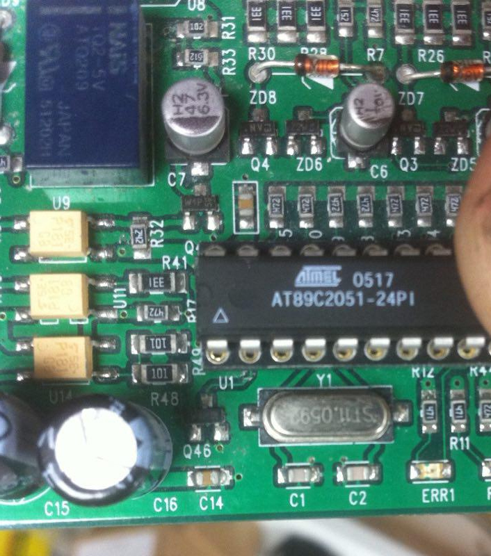
Main microcontroller
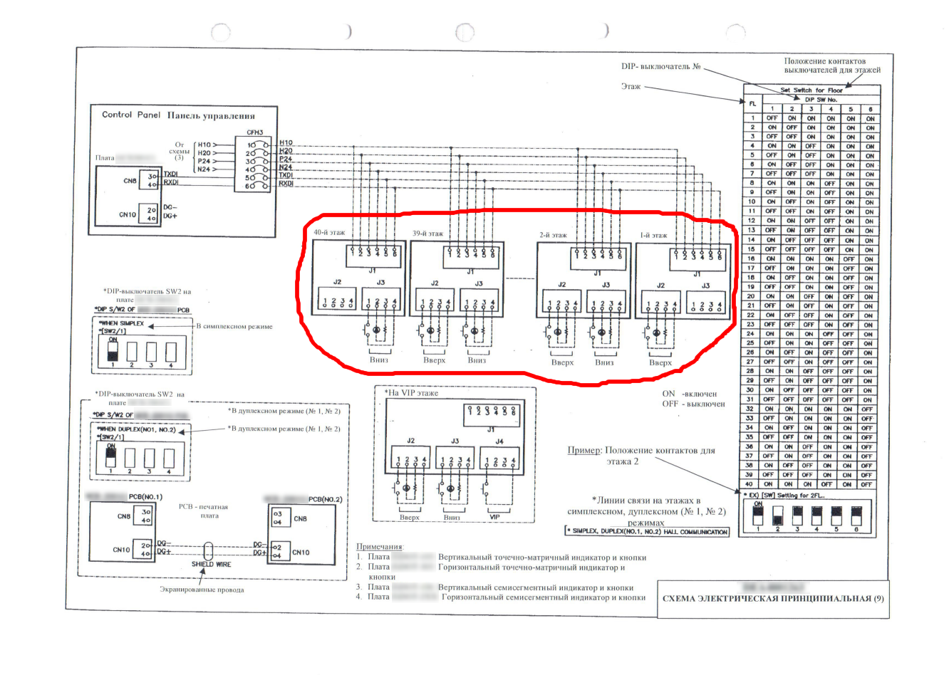
A piece of the electrical circuit of the elevator, on which our boards are circled in red
The board is assembled on a 1997 microcontroller, the AT89C2051 , which is based on the Intel MCS-51 architecture . In 2020, she celebrates her 40th anniversary in the embedded market.
A small explanation: a microcontroller is such a microcircuit that contains a computing core and a set of peripherals for controlling external devices. For example, in a modern washing machine, the microcontroller polls the control buttons, sensors, displays information on the screen and controls the pumps, heater, valves and drum drive. For most of these functions, it does not require intermediate devices, only a set of passive electronic components.
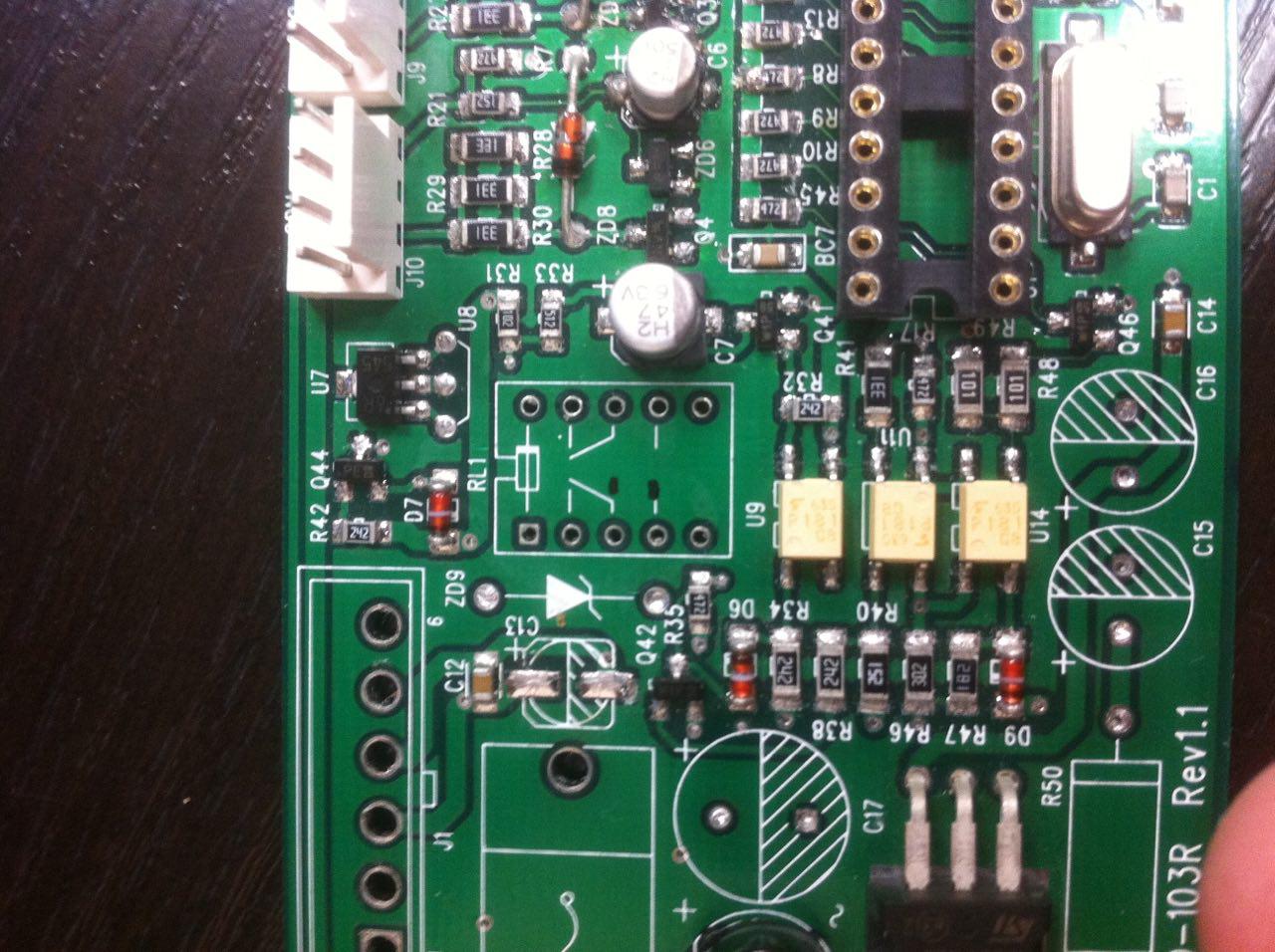
We disassemble the board for drawing the electrical
circuit Drawing the original circuit diagram of the board in the future will help to find out the pin assignment of the microcontroller, which is necessary to parse the firmware code.
The original device was developed by a Chinese company, and therefore its circuit is extremely confused and with many unnecessary components. For example, the relay was turned on through a triple cascade of a bipolar transistor, optocoupler and field device (in that order).
An acquaintance working with Chinese manufacturers told me that the Chinese are engaged in similar complications of schemes to increase the cost of development and production, if both people do it. After this, I am inclined to believe him:

The same place on the Chinese two-layer board on both sides. Three huge resistors are not connected to anything. I even shone the board with a powerful flashlight to make sure.
The scheme is copied, mysterious places are modeled in a multisim , we take up the firmware.
Trying to read the firmware
I was very lucky that the read protection was not enabled on both boards in the controllers, so I successfully merged the two firmware options with similar pornography:
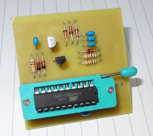
Photo from the personal blog of an American enthusiast
Disassembling firmware
The next step we need to convert this machine code into something more readable:

We take the famous IDA Pro tool , which already has our controller with all the peripheral registers, and open the HEX firmware file:

Processing the data received by the board in assembly language
After that, there is a rather tedious process of studying the instruction set of our computing kernel, commenting and decoding the assembler code.
Interrupt handlers themselves were found at the addresses of the interrupt vector table; entries in the peripheral registers gave information about the configuration of the communication interface. Step by step, the unnamed assembler code has turned into something that can be read.
Extraction of the algorithm of work
Since I needed to develop a new device on a different element base, it was necessary to extract an algorithm from the code. Some time later, such a pseudo code was born:
voidUartISR(void){
    counter500ms = 0;
    //ClearFlag(isrFlags, ISR_FLAG_3);
    ProcessUart(recievedByte);
}
voidProcessUart(uint8_t recievedData){
    staticuint8_t uartPacketsToRxLeft, uartRecievedCmd, uartCurrPacketCRC;
    staticuint8_t i, carryFlag;
    staticuint16_t uartIsrPointer;
    staticuint8_t uartBuffer1[8], uartBuffer2[6];
    staticuint8_t uartBuffer1Pos, uartBuffer2Pos;
    // 0 - // 1 - // 2 - // 3 - led state, 0x0F// 4 - // 5 - // 6 - // 7 - // 8 - buttons timestaticuint8_t dataRegisters[9]; // RAM:0050uint8_t tmpVal, i;
    uint8_t dataToSend;
    if (GetFlag(UartISRFlags, UART_RECIEVED_FLAG)) {
        ClearFlag(UartISRFlags, UART_RECIEVED_FLAG);
        if (recieved9thBit) {
            switch (recievedData) {
                case0xC1:
                    uartPacketsToRxLeft = 8;
                    uartRecievedCmd = 1;
                    uartBuffer1Pos = 0;
                    uartBuffer1[uartBuffer1Pos] = recievedData;
                    //uartIsrPointer = 0x0037;//tmpVal_0037 = recievedData;
                    uartCurrPacketCRC = recievedData;
                    UartRxOn();
                    return;
                    break;
                case0xC2:
                    uartPacketsToRxLeft = 3;
                    uartRecievedCmd = 2;
The same processing of received data in C
Who cares about the transfer protocol:
The elevator control station communicated with the call button boards via a full duplex 24-volt interface. In normal mode, the button boards listened for the line, waiting for a 9-bit data packet. If the address of our board came in this packet (it was set by the DIP switch on the board), then the board switched to 8-bit reception mode, and all subsequent packets were ignored by the rest of the boards in hardware.
The first after the address was a packet with a control command code. Specifically, this board took only 3 teams:
- Writing to data registers. For example, the frequency and duration of a button flashing on a call;
- Turn on the backlight of the buttons;
- Query the status of the buttons (pressed or not).
The last byte was the checksum, which is a simple XOR of all bytes after the address.
After the checksum, the board again went into standby mode of its address.
New board development
For the stage of developing a new wiring diagram and a printed circuit board, I have no pictures, but it was something like this:
Wiring and wiring were done in Altium Designer . The manufacture of the printed circuit board was ordered in Zelenograd “ Resonite ”.
Writing a new firmware
While our new board is in production, we go to the object where such call buttons are installed, and check the correctness of the disassembled transmission protocol using the sniffer assembled on the arduino: 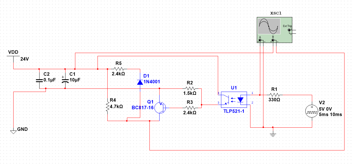
A piece of the transmitter circuit that is electrically equivalent to the original. The receiver is just an optocoupler.
//UART1 initialize// desired baud rate:19200// actual baud rate:19231 (0,2%)// char size: 9 bit// parity: Disabledvoiduart1_init(void){
 UCSR1B = 0x00; //disable while setting baud rate
 UCSR1A = 0x00;
 UCSR1C = 0x06;
 UBRR1L = 0x33; //set baud rate lo
 UBRR1H = 0x00; //set baud rate hi
 UCSR1B = 0x94;
}
#pragma interrupt_handler uart1_rx_isr:iv_USART1_RXCvoiduart1_rx_isr(void){
  unsignedchar tmp;
  unsignedint rcv = 0;
  if (UCSR1B & 0x02) {
    rcv = 0x100;
  }
  rcv |= UDR1;
  tmp = (rcv >> 4) & 0x0F;
  if (rcv & 0x100) {
    tmp |= 0xC0;
  }
  else {
    tmp |= 0x80;
  }
  txBuf12 = (rcv & 0x0F);
  txBuf11 = tmp;
  txState1 = 0;
  TX_ON();
  msCounter0 = 5000;
}
Talk about our sniffer in ICC AVR
Next, it was necessary to act extremely carefully so as not to burn anything in the elevator and prevent it from stopping.

We climb into the call button. Thick yellow wires - board power and transmission interface. White on the 4-pin connector - connecting the button and its backlight.
We check that everything works as it should, fix the jambs and write a new firmware for our device:
//ICC-AVR application builder : 11.02.2015 12:25:51// Target : M328p// Crystal: 16.000Mhz#include<macros.h>#include<iccioavr.h>#include<avrdef.h>#include"types.h"#include"gpio.h"#define TX_OFF()    UCSR0B &= 0b11011111;#define TX_ON()     UCSR0B |= 0b00100000;#define TX_STATE() (UCSR0B &  0b00100000)#define MAX_TIMEOUT 3000//#define SNIFFER_MODE 1//#define MASTER_MODE 1// #pragma avr_fuse (fuses0, fuses1, fuses2, fuses3, fuses4, fuses5)#pragma avr_fuse     (0xFF, 0xD1, 0xFC)#pragma avr_lockbits (0xFC)// AVR signature is always three bytes. Signature0 is always the Atmel// manufacturer code of 0x1E. The other two bytes are device dependent.#pragma avr_signature (0x1E, 0x95, 0x0F) // atmega32static GPIOx errorLed, rcvLed, butUp, butDn, ledUp, ledDn, butLedUp, butLedDn, ledButUp, ledButDn;
staticuint8_t msFlag = 0;
staticuint8_t ledState = 0, buttonsState = 0;
staticuint16_t rcvLedLitTime = 0, butMaskCalcTime = 0, timeoutTimer = 0;
typedefstruct {uint16_t buffer[10];
  uint8_t dataLength;
} UartPacket;
static UartPacket txPacket, rxPacket;
#ifdef SNIFFER_MODEstaticuint8_t txBuffer[64], txBufferLength = 0, bufferMutex = 0;
#endifstatic uint8_t GetPacketCRC(UartPacket* packet);
staticvoidSendLedState(void);
uint8_t GetAddress(void) {
  return (PINC & 0x3F);
}
C code for the new board based on the AVR ATmega328P microcontroller
The simplicity of the device and firmware can be estimated by the amount of code, it contains only about 600 lines in C language.
The build process looked like this:
The fee is different, but the principle is the same
I can’t attach a photo of the finished device, just believe that it is still being produced and sold.
Lyrical conclusion
Regarding the elevator buttons “up” and “down” on the floor. I noticed that many people completely do not understand their purpose and shake both at once.
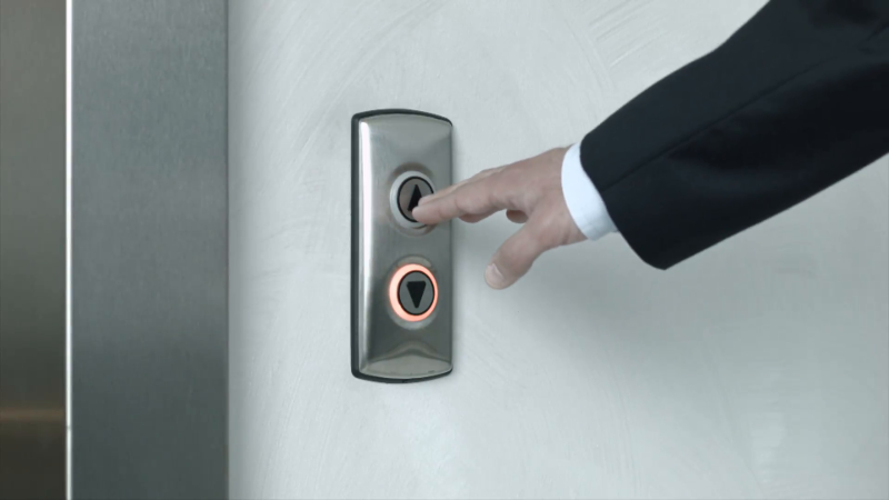
The elevator has two sets of buttons: in the cab there is an order panel, and on the floor there is a call panel. You can already guess from the name that the order panel has a higher control priority.
All elevators with call panels with up and down buttons work with one of the options for the travel optimization algorithm, the purpose of which is to transport the maximum number of passengers in the minimum time and a separate condition for the maximum waiting time on the floor (regulated by state standard).
Such an algorithm usually involves the selection of passengers on floors if they are traveling in the same direction as indicated by pressing the call button “up” or “down”.
Imagine a situation where an elevator with passengers travels down and receives a “down” call from a floor below. The elevator will stop to pick up the passenger (yes, there is still accounting for the cab loading by the weight sensor, but we will lower it).
The elevator goes on and receives a call “up” from the floor below. It is logical that the elevator will not stop to pick up a passenger, since it will not change the direction of travel (this is also regulated by the standard), but pick up a passenger to go down and then up - useless consumption of energy and space in the elevator.
The elevator goes on and receives two calls “up and down” from the floor below, which were pressed by some impatient passenger who needs to go up. It is logical that the elevator will stop on this floor, but the passenger will not enter it, but it will take the time of people in the cabin to slow down and stop the elevator, open doors, wait, close doors and accelerate to rated speed.
If the elevator has only one button on the floor, then in 99% of cases it works according to the “collective down” algorithm, and if there are orders in the cabin, it stops only when moving down.
If you have programming skills in JS, then you can try to implement a similar control algorithm in the online game Elevator Saga . It has all aspects of optimizing trips without going deep into hardcore like the operation of elevator safety circuits.
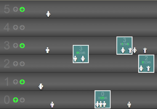
In my telegram channel I post similar materials. Right now there you can follow the development of the next device.









