May 1, 2019 at 18:13
Zastone ZT-A19 Radio: Performance Measurement
I recently purchased a Zastone ZT-A19 wearable radio station. After studying various forums, reviews and reviews, it seemed to me that this radio station would be a good price-quality compromise. I made this conclusion relying more on reviews about the brand than on this particular model. And at that time, and now there are very few reviews on the Zastone ZT-A19 radio station on the Internet, and so I decided to personally measure the characteristics of the radio station and share them, as they say, with the public. I used an amateur device - SWR meter SW-33, also ordered in one popular online store. In my experiment, I measured two characteristics: the output power of the radio station itself and the SWR of a standard antenna in the frequency range. See the results of my research below.

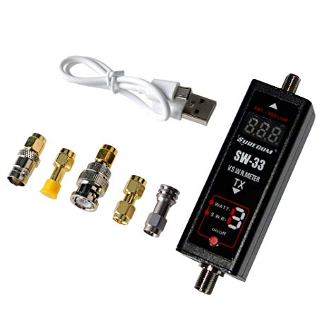
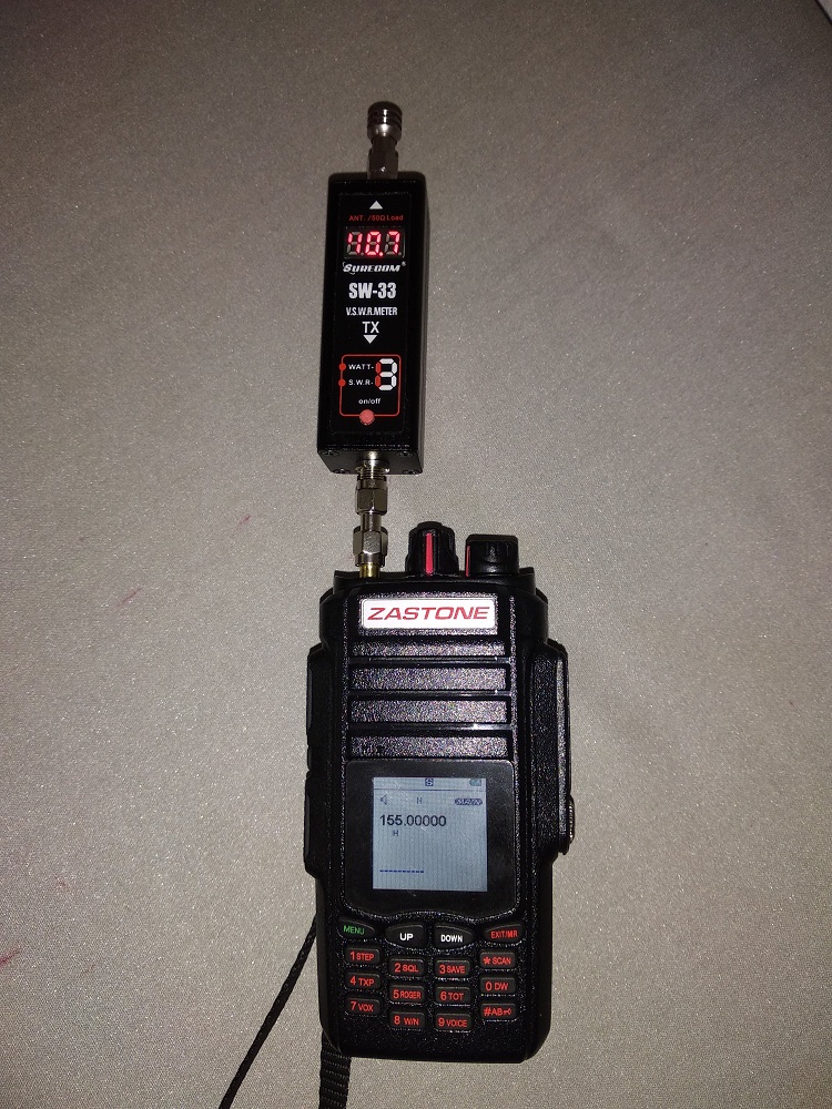
For measurements, an amateur SWR meter SW-33 was used. The characteristics of the SWR meter are given above. The SWR meter has two connectors: input and output. The input connector of the SWR meter is connected to the antenna connector of the radio station. A 50-ohm SMA resistor can be connected to the output connector of the SWR meter to measure the output power, or some antenna to measure the SWR antenna. The measurements were carried out for two power settings in the “HIGH” position and in the “LOW” position in two frequency ranges VHF and UHF with a certain constant frequency step. Below are tables and graphs of measurements.
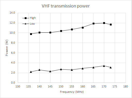

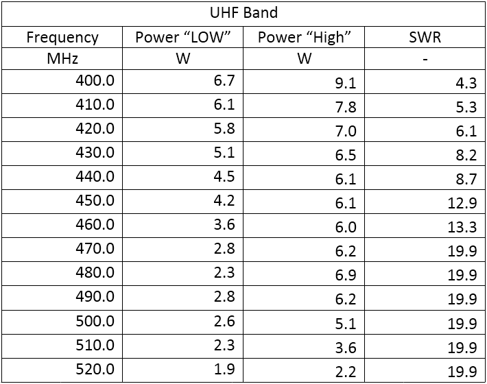
As we can see, in the VHF range, the radio station confidently delivers the declared 10 watts at maximum power. However, in the UHF range, the output power decreases strongly with increasing frequency and does not reach the declared 10 watts.
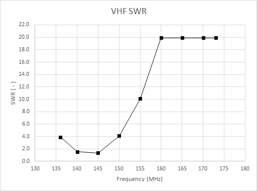
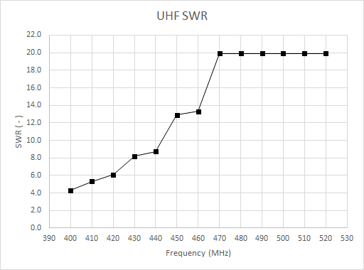
Both in the specification of the radio station and on the connector of the antenna itself the operating frequency ranges 400 - 480 MHz / 136 - 174 MHz are declared. Nevertheless, the graphs show that a good SWR for a standard antenna happens only in the range 140 - 145 MHz and is approximately 1.50. In the ranges 136 - 140 MHz, 145 - 160 MHz, 400 - 470 MHz, the SWR is, strictly speaking, bad. And in the ranges 160 - 174 MHz and 470 - 480 MHz, the device is off scale, that is, the SWR is very bad.
Below are the measurement tables:

We found that the radio station does not reach the declared power. The quality of tuning the standard antenna to the declared frequency ranges leaves much to be desired. However, one should not think that this radio station is bad. I think if we take similar measurements for any other radio station, for example, Baofeng UV-5R, then the results will be similar or even worse. But I did not conduct such tests.
It is clear that providing output power in the entire frequency range is a difficult task from the point of view of radio electronics, as well as the task of tuning the antenna. And yet, I believe that the manufacturer here is clearly not finalized. Personally, I just plan to buy a better antenna for this radio station, and the output power suits me perfectly. I also urge readers to conduct similar experiments with other popular radio stations and share the results in the comments.
A 50 ohm resistor is the ideal matched load for the output stage of a radio transmitter. At high frequencies, the radio waves propagate through the wires, obeying the wave equation, and therefore they can partially be reflected back from some parts of the circuit, for example from some resistance in the line, or inductance. The antenna is an imperfect element. It has its own frequency response with resonances by other effects, and therefore almost always the antenna partially reflects the power coming into it back to the transmitter. This phenomenon is undesirable and even harmful, since, firstly, the reflected power is released in the transmitter in the form of heat, and secondly, it reduces the power radiated to the ether. We want to simulate a situation when all the power is “radiated”. Therefore, instead of the antenna, you need to use a 50 ohm resistor,
SWR, aka SWR, is the coefficient of the standing voltage wave, which just characterizes the number of reflections in the transmission line. When the line is not consistent, then along with the incident (useful) wave, a reflected (undesirable) wave appears in it. As we know from physics, two waves going towards each other form a standing wave. The standing wave coefficient shows how large the reflected wave is compared to the incident wave. The smaller the SWR, the better. With a complete lack of reflection in the line, the SWR is equal to unity. The values of the SWR are considered good in the range 1 - 2. If the SWR is very large, this means that the line is not consistent and the radio wave experiences strong reflections.
The wave resistance is the ratio of the amplitudes of the electric and magnetic fields in the transmission line. When an electromagnetic wave propagates along a transmission line, then the maxima of the electric and magnetic field intensities alternate in the line. Since the electric field is measured in V / m, and the magnetic field is in A / m, then if you divide one into the other, you get Ohms. This value characterizes the effective resistance of the entire transmission line as a whole.
In radio engineering, there are two harmonization standards: 50 and 75 ohms. The 75 ohm standard is a coaxial cable with minimal loss, and the 50 ohm standard is a compromise between the minimum loss and maximum electrical strength, which is achieved in a coaxial cable with a value of impedance of about 30 ohms. These are the values of wave impedances, for which all electronic circuits are calculated. For example, when you connect a coaxial cable with a wave impedance of 50 Ohms to a radio transmitter, the transmitter will “see” at its input as if a resistor of 50 Ohms, but only on condition that the cable is infinitely long. In reality, this does not happen, and then something else, for example, an antenna, is usually connected to the coaxial cable. An ideal antenna should have a wave impedance of 377 ohms, the same as the wave resistance of the vacuum, therefore, in the gap between the antenna and the coaxial cable (feeder), a matching transformer is often turned on, which reduces the antenna resistance from 377 to 50 Ohms to the transmitter input. In this case, in all parts of the circuit, the radio waves “see” the same wave resistance, and do not bounce back to the transmitter. In addition, the reception quality is also improved.
If you still have questions, please write in the comments - I will try to answer.
Radio Station Zastone ZT-A19
Radio Options
- Brand: ZASTONE
- Model Number: ZT-A19
- 10 high power
- Frequency range: 400 - 480 MHz / 136 - 174 MHz
- Channel capacity: 999
- Antenna: Professional antenna
- Capacity of battery: 2800 mAh
- Operating voltage: DC 7.4 V
- Impedance of antenna: 50 Ω
- Dimensions: 125 x 56 x 31 mm
Measuring the characteristics of a radio station and a standard antenna
SWR meter parameters
- Model No. SW-33
- Max Power: 0.1 - 100 W
- VSWR: 1.00 - 19.9
- Frequency Range: 125 - 525 MHz
- Power in: 5 V (micro usb)
- Li-ion Battery: 3.7 V 500 mAh
- In / Out Impedance: 50 Ω
- Size without Socket: 25 x 25 x 60 mm
- Interface: SMA Female
- Net Weight: 160 g
For measurements, an amateur SWR meter SW-33 was used. The characteristics of the SWR meter are given above. The SWR meter has two connectors: input and output. The input connector of the SWR meter is connected to the antenna connector of the radio station. A 50-ohm SMA resistor can be connected to the output connector of the SWR meter to measure the output power, or some antenna to measure the SWR antenna. The measurements were carried out for two power settings in the “HIGH” position and in the “LOW” position in two frequency ranges VHF and UHF with a certain constant frequency step. Below are tables and graphs of measurements.
Power measurement
As we can see, in the VHF range, the radio station confidently delivers the declared 10 watts at maximum power. However, in the UHF range, the output power decreases strongly with increasing frequency and does not reach the declared 10 watts.
SWR measurement of a standard antenna
Both in the specification of the radio station and on the connector of the antenna itself the operating frequency ranges 400 - 480 MHz / 136 - 174 MHz are declared. Nevertheless, the graphs show that a good SWR for a standard antenna happens only in the range 140 - 145 MHz and is approximately 1.50. In the ranges 136 - 140 MHz, 145 - 160 MHz, 400 - 470 MHz, the SWR is, strictly speaking, bad. And in the ranges 160 - 174 MHz and 470 - 480 MHz, the device is off scale, that is, the SWR is very bad.
Below are the measurement tables:
conclusions
We found that the radio station does not reach the declared power. The quality of tuning the standard antenna to the declared frequency ranges leaves much to be desired. However, one should not think that this radio station is bad. I think if we take similar measurements for any other radio station, for example, Baofeng UV-5R, then the results will be similar or even worse. But I did not conduct such tests.
It is clear that providing output power in the entire frequency range is a difficult task from the point of view of radio electronics, as well as the task of tuning the antenna. And yet, I believe that the manufacturer here is clearly not finalized. Personally, I just plan to buy a better antenna for this radio station, and the output power suits me perfectly. I also urge readers to conduct similar experiments with other popular radio stations and share the results in the comments.
Explanations for those who are new to radio technology
Why do I need a 50 ohm terminal resistor instead of an antenna when measuring output power?
A 50 ohm resistor is the ideal matched load for the output stage of a radio transmitter. At high frequencies, the radio waves propagate through the wires, obeying the wave equation, and therefore they can partially be reflected back from some parts of the circuit, for example from some resistance in the line, or inductance. The antenna is an imperfect element. It has its own frequency response with resonances by other effects, and therefore almost always the antenna partially reflects the power coming into it back to the transmitter. This phenomenon is undesirable and even harmful, since, firstly, the reflected power is released in the transmitter in the form of heat, and secondly, it reduces the power radiated to the ether. We want to simulate a situation when all the power is “radiated”. Therefore, instead of the antenna, you need to use a 50 ohm resistor,
What is SWR?
SWR, aka SWR, is the coefficient of the standing voltage wave, which just characterizes the number of reflections in the transmission line. When the line is not consistent, then along with the incident (useful) wave, a reflected (undesirable) wave appears in it. As we know from physics, two waves going towards each other form a standing wave. The standing wave coefficient shows how large the reflected wave is compared to the incident wave. The smaller the SWR, the better. With a complete lack of reflection in the line, the SWR is equal to unity. The values of the SWR are considered good in the range 1 - 2. If the SWR is very large, this means that the line is not consistent and the radio wave experiences strong reflections.
What is wave impedance?
The wave resistance is the ratio of the amplitudes of the electric and magnetic fields in the transmission line. When an electromagnetic wave propagates along a transmission line, then the maxima of the electric and magnetic field intensities alternate in the line. Since the electric field is measured in V / m, and the magnetic field is in A / m, then if you divide one into the other, you get Ohms. This value characterizes the effective resistance of the entire transmission line as a whole.
What is a consistent line?
In radio engineering, there are two harmonization standards: 50 and 75 ohms. The 75 ohm standard is a coaxial cable with minimal loss, and the 50 ohm standard is a compromise between the minimum loss and maximum electrical strength, which is achieved in a coaxial cable with a value of impedance of about 30 ohms. These are the values of wave impedances, for which all electronic circuits are calculated. For example, when you connect a coaxial cable with a wave impedance of 50 Ohms to a radio transmitter, the transmitter will “see” at its input as if a resistor of 50 Ohms, but only on condition that the cable is infinitely long. In reality, this does not happen, and then something else, for example, an antenna, is usually connected to the coaxial cable. An ideal antenna should have a wave impedance of 377 ohms, the same as the wave resistance of the vacuum, therefore, in the gap between the antenna and the coaxial cable (feeder), a matching transformer is often turned on, which reduces the antenna resistance from 377 to 50 Ohms to the transmitter input. In this case, in all parts of the circuit, the radio waves “see” the same wave resistance, and do not bounce back to the transmitter. In addition, the reception quality is also improved.
If you still have questions, please write in the comments - I will try to answer.