How does Mr. Televox work? Patent with schemes
- Transfer

Looking at the KDPV, many readers will immediately recognize the ingenious invention called “Mr. Televox”. Too much he fell in love with the authors of Soviet popular science books, who did not miss the opportunity to mention him on occasion. But how much do we know about him, besides the fact that he answered telephone calls and switched electric circuits by the sounds of various frequencies? I wish I could find out a little more.
When an article about him appeared on the Hackaday blog, I decided to ... not translate it. Since there is not much more information there, except for a couple of little-known facts: first, while traveling, the developers carried only the “box” with them, and each time they cut the flat anthropomorphic figure in place again, and secondly, the device was made using Knowles lamps close to thyratrons (as it turned out, no - the lamps are ordinary). Geek wants schemes, and they were found with the patent. Which I translate.
“My invention relates to alarm systems, and more specifically to systems of the so-called. dispatch control, where remote switches or other devices are remotely controlled and monitored from a central control center.
The increase in the number of energy transmission systems with many small loads located close to each other made the presence of operators near each of them expensive and impractical.
To circumvent this limitation, such dispatch control systems have been invented where switching devices located next to the loads are selectively controlled and monitored by one operator along signal lines from the control room. This turned out to be more effective than having many operators next to each of the loads.
But in order to selectively control and monitor remote loads, it turned out to be necessary to develop an alarm system with characteristics adapted for dispatch control. For this, for example, it was necessary to accurately select which load to manage. But at the same time, switching is made infrequently. In the initial position, the load is disconnected, and it should be ready for start-up at any time, either manually by the operator or automatically.
The requirement for faultless control and monitoring of switching devices has led to the development of very complex and expensive systems. In addition, the cost of the lines laid between the dispatcher’s office and the locations of the control objects is added. For additional reliability, the lines laid to the control facilities distributed over the served territory are duplicated. And since switching is infrequent, most of the time these lines are idle.
But between the dispatcher’s office and the loads controlled from there, telephone lines are usually laid. Information can also be transmitted via them, but telephone companies oppose this and do not allow other types of signals other than speech to exchange these lines. Yes, and the lines themselves are little adapted to transmit other signals. The fears of telephone operators will no longer be justified if these signals are given characteristics close to those of speech signals. It turned out that signals at frequencies similar to those of human speech are also suitable for remote control of switching devices and monitoring their state.
The subject of the invention is:
- the use of telephone lines for tele-control and tele-signaling in such a way as to prevent telephone companies from finding fault with the characteristics of the transmitted signals
- the use of such signals to manage loads and monitor their condition from the central control room
- management of telephone sets in locations of control objects from the same office
- using standard telephone sets as subscriber devices
- selectively interacting with many control objects from one control room
All of the above can be carried out individually and together in various combinations.
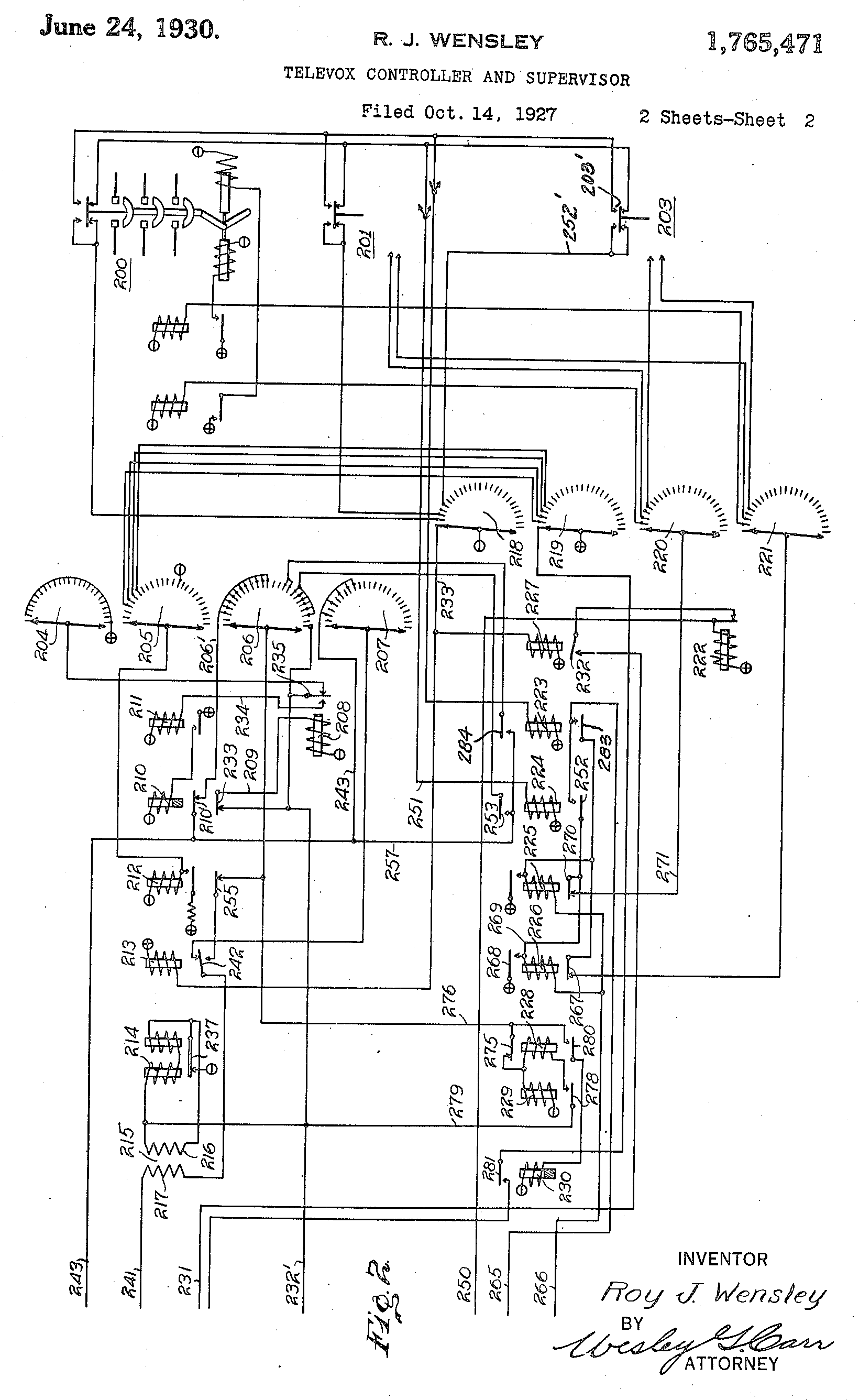
In fig. 1 shows a diagram of a device located in the dispatcher’s office, as well as a receiving device at the control object, in fig. 2 is a logic diagram on relays and searchers on the same object.
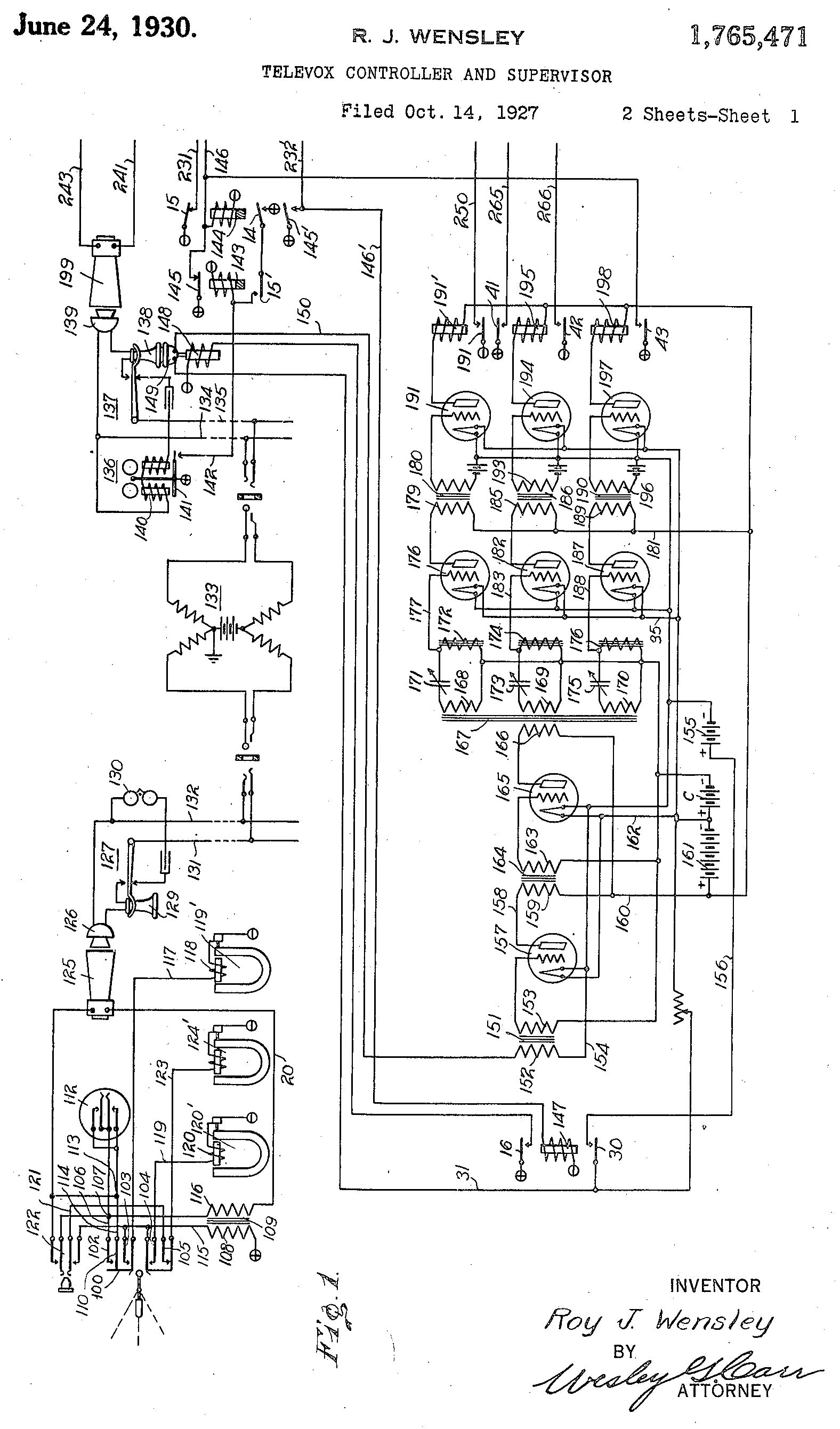
Key 100 consists of contact groups 102, 103, 104 and 105, while group 105 is normally closed. The conductor 106 goes to the point 107, and from there to the secondary winding 116 of the transformer 109. The movable contact 102, closing on the fixed contact 110, shorts the standard telephone dialer 112, connecting the point 113 through the conductors 114 and 106 with the point 107. This will be described in more detail below . The movable contact 103 is connected through the conductor 115 to the primary winding 108 of the transformer 109. When the corresponding contact group is closed, this circuit also connects through the conductor 117 to the buzzer 118 of the buzzer 119 '. The buzzer 119 contains a tuning fork defining the frequency of the oscillations generated by it. Buzzer 120 ', 124' and 119 'are tuned to different frequencies,
The movable contact 104 is connected by a conductor 119 through the buzzer 120 winding 120 'and through the conductor 115 to the power switch through the multi-turn winding 108 of the sound transformer 109. When the buzzer winding 120' circuit is closed, a tone package is received that allows you to select (as described below) ), which remote switch to control on a remote object.
The movable contact 105 is connected by a conductor 121 to a key 122, and a conductor 123 (when the contacts are closed) is connected to a buzzer winding 124. At the same time, an audio frequency signal is supplied to the telephone line to transfer the selected remote switch to the desired position. The disk dialer 112 interrupts the current in the secondary circuit 108 of the transformer 109, which flows to a standard sound emitter located near the microphone 126 of a standard telephone set 127. The device consists of a microphone 126 and sound emitter 129 connected in the usual way through a call 130 to a telephone line (conductors 131, 132 ), and further with the telephone exchange.
Telephone exchange schematically depicted as pos. 133 - standard, many lines come to it, and any two of them can be connected in such a way as to provide communication between the calling and called subscribers.
A line of conductors 134, 135 is drawn from the telephone exchange to the facility where the remote switches are located, requiring control and monitoring. The line is connected to the same telephone set, consisting of a bell 136, a sound emitter 138 and a microphone 139. A bell 136, consisting of a coil 140 and a moving part 141, responds to a call signal from a telephone exchange, intermittently connects the plus of the power source to the wire 142, connected to the winding of a relay 143 with a release delay. In the initial state, a normally closed contact group 145 of this relay connects the plus of the power source to the relay coil 144 also with a release delay. The relay coil 144 is controlled not only by contact group 145, but also contact group 281 along conductor 146 to return the device to its original position in the manner described below.
Relay 144, by its contact group 145 ', controls the circuit for transferring the device to the on state from its initial position in the manner described below. The contact group 145 'is connected by a conductor 146' to the coil of the relay 147, in which there is no voltage in the initial position, but appears when the relay 144 is released when a call comes from the telephone exchange, in the manner described below.
Relay 147, when activated, turns on a solenoid 148 that picks up the handset 138, which is why the same switches occur in the telephone set as when a person picks up the handset. Also, when this relay is activated, power is supplied to the lamps described below. At the time of picking up the handset, a connection is made between the dispatcher’s office through telephone lines, devices and the station with a remote object in the manner described below. The sound emitter 138 acts on the carbon microphone 149, controlling the flow of current through the conductor 150 in accordance with the form of sound vibrations.
The conductor 150 is connected in series with the primary winding 152 of the transformer 151, and then through the conductor 154 - with the battery 155, and through ne1 - with the conductor 156.
The secondary winding 153 of the same transformer is connected to the grid of the lamp 157. This lamp consists of a cathode, a grid and an anode, and is turned on in the usual way, used for amplifying audio signals (not quite ordinary - there is no decoupling for direct current and bias - translator). The anode of the lamp is connected by a conductor 158 to the primary winding 159 of the sound transformer 164, then through it with a conductor 160, a battery 161, a conductor 162 and a thread of the same lamp. The secondary winding 163 of the transformer 164 is connected to the grid of the lamp 165, similar to the lamp 157. Such a two-stage amplifier is known and is not the subject of the invention.
The lamp 165 controls the primary winding of the sound transformer 167. Its secondary windings 168, 169 and 170 are connected to circuits consisting of capacitors 168, 169 and 170 and inductors 172, 174 and 176 '. The circuits are tuned to the same frequencies as the buzzer 120 ', 124' and 119 'in the controller's office.
The grid of the lamp 176 is connected by a conductor 177 to a circuit that includes an inductor 172. The anode of the same lamp is connected by a conductor 178 to the primary winding 179 of the sound transformer 180, then a conductor 181 with a battery 161 connected to the filament of the same lamp. The grid of lamps 182 and 187 are similarly connected to circuits, which include inductors 174 and 176 ', and their anode circuits control the primary windings 185 and 189 of the sound transformers 186 and 190.
The signals from the secondary windings of the transformers 180, 186 and 190 are amplified by the lamps 191, 194 and 197 in the same manner. But they have a negative bias from small batteries, so without a signal, current does not flow through their anode circuits. When a signal arrives at the grid of one of the lamps, it turns on the relay winding, respectively, 192, 195 or 198.
We proceed to Fig. 2, two-winding remote switches 200, 201 and 203 are shown here, although there may be more of them, along with the other nodes controlling them. The step finders 204 - 207, each of which consists of a movable contact and a set of fixed ones, are controlled by a winding 208. They determine which signals will be sent back to the dispatcher, informing him of the current state of the remote switches in the manner described below.
The winding 208 through a conductor 209 is connected to a normally closed contact group 233, controlled by the method described below, to change the position of the step finders 204 - 207. A relay with a delayed response 210 is connected so that the voltage on its winding appears and disappears synchronously with the voltage on the winding 208 The interaction of these relays leads to the fact that pulses arrive at the winding 208, and the step finders switch, choosing various signal sources for transmitting data about their state to the dispatcher. Relay 211 is intermediate between relay 210 and step finder coil 208.
The switching circuit of the relay 212 is controlled by the contacts of the finder 205, choosing a device whose status signal will be sent to the dispatcher in the manner described below. The relay 213 in the initial state is on, and together with the relay 212 controls the supply of code signals to the movable contacts of the searchers 204 - 207 so that the code of either the selected remote object or the load is transmitted. The buzzer 214 commutes the bell transformer 215, consisting of a primary winding 216 and a secondary winding 217 to receive an audio signal that is interrupted in accordance with the object code and the selected load.
The second set of searchers 218 - 221 is selectively controlled according to the code combination of pulses coming from the dispatcher's office to select a remote switch that will be controlled as described below. The movable contacts of these searchers are controlled by a winding 222, which, in turn, is controlled by the contact group 191 of the relay 191 ′ in the manner described below.
Relays 223 and 224 are common to all remote switches, and when the movable contact of the finder 218 moves from one fixed contact to another, one of these relays is activated depending on whether the remote switch is switched on or off, to the status contacts of which it is connected at this moment movable contact of this finder. Relays 225 and 226 are also common to all remote switches, and they are controlled by a final control pulse coming from the control room to close the circuits that carry current through the contacts of relays 223 or 224, depending on which one is currently on .
Relay 227 controls the winding 222 switching step finders. Also, the same winding controls a group of normally closed contacts. When an object is selected, a buzzer resemblance is obtained, which is activated via the contact group of the relay 227, in the manner described below. The movable contacts of the finders move until they return to their original position. Relays 228 - 230 are turned on by the method described later, after selecting a remote object, and return the device to its original position with a certain delay. Thus, if the operator at the telephone exchange accidentally connects someone other than the dispatcher to the remote object, the device will soon return to its original position automatically.
So, the connection is established, the remote switch, the status of which you want to change, is selected. What happens next?
Suppose the dispatcher decided to turn on the remote switch 203, shown in the diagram in the off state. First, he asks the operator at the telephone exchange to connect him to the corresponding object, and he connects.
Call 140 starts ringing, contact group 141-142 closes, voltage is applied to relay coil 143.
When voltage is removed from this winding, relay 144 is turned on via normally closed contact group 145, which makes the state of its contact groups 14, 145 'and 15. Changes group 15 and the conductor 231 is prepared for the inclusion circuit of the winding of the step finders 222, but the current has not yet passed, because the group 232 of the relay 227 is open.
In the initial position, the power circuit of the relay 213 and 227 is closed along the conductor 233, the first stationary contact of the finder 218 and its movable contact to the negative of the battery.
When the relay 143 is activated in the manner described above, the relay 144 is turned off, the contact group 145 opens. After some time, the group 14 of the relay 144 closes, and the relay 143 self-locks: the battery plus is connected through the group 14, then the group 15 ', with the relay coil 143, the opposite terminal of which is connected to the minus. Relay 143 remains on until it receives a signal to turn it off in the manner described below.
A further result of turning off the relay 144 is the opening of the step-by-step search coil 222, which was prepared through group 15, as well as the closing of the relay-on circuit 147 through group 145 '.
The plus of the battery is connected through group 145 'and conductor 232' with the winding of the buzzer 214, then with the minus of the battery. This chain is described in more detail below.
The actuation of the relay 147 is followed by the raising of the tube by the solenoid 148, controlled by the group 16. The
microphone 149 begins to receive sounds as soon as the tube with the sound emitter 138 is removed, which causes the current in the conductor 150 to change in accordance with the sound vibrations coming from this sound emitter.
Together with the switching circuit of the relay 147, the winding circuit of the searchers 208 is also closed through the conductor 209, group 233, conductor 233 'and group 145'. The movable contacts of the searchers 204-207 are prepared for the transition to the next position. The relay switching circuit 211 is closed through group 235, conductor 234, conductor 232 'and group 145'.
Relay 211 turns on relay 210. Group 233 opens the power supply circuit to the windings of the finders 208, and the stepper finders switch to the second position. The relay with a delayed release 210 is turned off after the relay 211 is turned off, and after some time its contacts open. Group 233 closes, voltage is applied to winding 208, and the finders are again prepared for switching.
Thus, the alternate actuation of the coil of the finders 208 and the relay with a delayed release 210 leads to the movement of the movable contacts of the finders on different stationary contacts.
When the finder 204 switches to the triple position, the power circuit of the winding 208 is prepared through the finder 204 together with the circuit passing through group 145 ', and the winding starts to turn on periodically regardless of the state of the relay 144 immediately after the finder is in the second position (because all the fixed contacts of the finder 204, except the first, connected together).
So, the seekers are starting to switch. Recall that with the relay 144 turned off and the group 145 'closed, the buzzer 214 closes. When the buzzer vibrates, pulses with the frequency at which the buzzer is configured are sent to the primary winding 216 of the bell transformer 215. The circuit closes: minus batteries, group 237, buzzer coil 214 primary winding 216, conductor 232, group 145 ', plus batteries.
When an intermittent current passes through the primary winding 216 of the transformer 215, an alternating voltage is induced in the winding 217 to the sound emitter 199 through the following circuit: conductor 214, winding 217, group 242, finder 207 in the third position, conductor 243, second output of the sound emitter 199. In addition to the third position of the seeker, the same circuit closes when he is in the fifth, seventh, ninth and tenth positions. Thus, the dispatcher receives five tone parcels, while the fourth and fifth parcels almost merge into one long one. On another remote object, the fixed contacts of the same crawler are connected in a different way so that the dispatcher receives a different code.
The tuning frequency of the buzzer 214 is in the range of human speech, which should not cause complaints among telephone operators. The dispatcher listens to the code and determines whether it is connected correctly - with the remote object that it needs.
After making sure that everything is correct, the dispatcher presses the key, group 104 closes, voltage is applied to the winding 120 of the buzzer 120 '. An audio signal is supplied to the primary winding 108 of the sound transformer 109. From the secondary winding 116, the signal is transmitted to the sound emitter 125 through the dial dialer 112. On it, the dispatcher dials the number 5, and the same number of tonal messages are received. The microphone 126 “hears” them, and the corresponding signals arrive at the telephone station via line 131, 132.
At a remote site, a sound emitter 138 emits these sounds into a microphone 149, whereby the current through conductor 150 begins to change accordingly. It enters the primary winding 152 of the sound transformer 151 through the following circuit: microphone, primary winding, conductor 154, battery 155, conductor 156, group 30 of relay 147, turned on as described above, and conductor 31. The signal is amplified by lamp 157, transmitted through transformer 164 to the lamp 165, and after amplifying it to the winding 166 of the transformer 167. Since the oscillation frequency of the buzzer 120 'corresponds to the tuning frequency of the circuit 168, 171, the signal from it goes to the lamp 176, amplifies it and goes to the primary winding 179 of the transformer 180. Lamp 191 enhances and in straightens the signal, causing switch 191 'is activated.
Turns on the winding 222 of the searchers 218-221 in the following circuit: plus batteries, group 192, conductor 250, winding 222, minus the batteries. Searchers are preparing to switch to the next position. When the contacts of the dialer 112 are opened for the first time, the relay 191 is turned off, the voltage is removed from the winding 222, and the finders are switched.
The crawler 218 in the second position turns off the relays 227 and 213. The relay 227 prepares the circuit for turning on the search winding through group 232, but it is not yet closed, since relay 144 has not tripped.
Releasing the relay 213 causes the circuit to open through the finder 207, along which the signal the code of the selected remote object, since group 242 is switched. A circuit is prepared through the finder 206 to signal the selection of the remote switch in the manner described below.
By the time the dispatcher sends five pulses by the dialer, the relay 191 'turns on and off five times. The same thing happens with winding 222 of searchers 218-221.
When the searchers reach the fifth position, the power circuit of the relay 224 closes, since the remote switch 203 is in the off position. A circuit is closed from the battery, the relay coil 224, the conductor 251, the state contact 203 'of the remote switch 203, the conductor 252', the finder 218 in the fifth position and the battery minus.
When relay 224 is turned on, the relay 226 enable circuit is prepared through group 252, but this circuit has not yet been closed, since relay group 41 is open 195. The signaling state of the remote switch through group 253 is closed. It consists of a sound emitter 199, conductor 241, and a secondary winding 217 of transformer 215, group 242, group 255, searcher 206, conductor 206 ', group 210' and conductor 243 to the opposite terminal of the sound emitter.
When turning on and off the windings of the finders 208 and the relay with a delay of releasing 210 in the manner described above, the signal supply circuit to the sound emitter is closed and opened by the finder 206. When the finder 205 moves to the seventh position, the relay 212 is switched on in this way: minus the batteries, relay coil 212 finder 205 in seventh position, conductor 260, finder 219 in fifth position, plus batteries. Relay 212 is activated, self-locking by group 212 ', and group 255 interrupts the supply of a surveillance signal. The number of signals that the dispatcher will hear before this corresponds to the number of the remote switch.
When the finder 205 reaches the fifteenth position, the coil of the relay 212 is short-circuited (which is tin, but according to the circuit it is), why it is released, preparing to transmit a signal for monitoring the status of the remote switch. This signal is emitted when the finder 206 reaches position 16 or 18, respectively, through group 269 (actually 284) or 253 and conductor 257 to conductor 243, depending on whether the remote switch is closed or open. If the circuit is closed through the finder in position 18 and group 253, a long beep sounds because the circuit is closed all the time while the finder goes through positions 18 to 23. If the remote switch is on, a short beep sounds because the finder switches from position 16 to position 17 faster. So the dispatcher finds out
The dispatcher presses the key, group 105 closes, the second buzzer 124 'is turned on in the following circuit: minus the batteries, group and coil of the buzzer, group 105, conductor 121, group 122, coil 108 of transformer 109, plus batteries. The sound emitter 125 emits a sound into the microphone 126, the signal passes through the telephone exchange, is repeated by the sound emitter 138 and is perceived by the microphone 149. Then it passes through the transformer 151, amplified by the lamps 157 and 165, enters the winding 166 of the transformer 167, excites oscillations in the circuit 169-173, amplified by a lamp 182, passes through a transformer 186, amplified by a lamp 194 and turns on a relay 195.
The switching circuit of relay 226 closes: plus batteries, group 41, conductor 265, group 252, relay coil 226, conductor 266, group 42, minus batteries.
The remote switch disconnect solenoid circuit is opened by group 267, and its turn-on electromagnet circuit is opened by group 268: plus batteries - group 268, conductor 269, group 270, conductor 271, searcher 220 in fifth position, the inclusion electromagnet (not shown) of remote switch 203.
Remote the switch 203 goes into the on position, its state contact 203 'is switched in such a way that the switching circuit of the relay 224 is opened, and the switching circuit of the relay 223 closes: plus batteries, relay coil 223, status contact 203', finder 218 in fifth position, minus batteries. Relay 223 by group 283 prepares the switching circuit of relay 225, which will be needed when voltage is again required on the trip solenoid. Group 284 prepares an observation signal supply circuit.
After changing the position of the finder 206, the signal supply circuit to the sound emitter 199, previously consisting of conductors 257 and 243 and group 253, is opened. Now the circuit passing through group 284 is closed. It consists of sound emitter 199, conductor 241, secondary winding 217 of transformer 215, groups 242 and 255, the finder 206 at position 16 or 17, group 284, conductors 257 and 243, and the opposite output of the sound emitter.
Now the dispatcher presses the key 100, the group 103 closes, the buzzer 119 'turns on, and the signal with the frequency of its adjustment enters the primary winding 108 of the transformer 109. It passes through the sound emitter 125, microphone 126, telephone exchange 133, and so on, eventually calling actuation of relay 198. Group 43 includes relay 144, the self-locking circuit of relay 143, which includes groups 14 and 15, is opened by group 14. The wiring circuit of the finders 208 and relay 147 is opened by group 145 '.
If the finder 204 is not in the first position at the moment of opening the power circuit of the winding 208 by turning on the relay 144, the closure circuit of the winding 208 is closed, which is independent of the relay 144. This circuit consists of the plus of the battery, the finder 204 in any position except the first, groups 235 and 233 and battery minus. Relay 210 cannot be turned on until relay 144 is turned on. But when coil 208 is turned on, group 235 opens, the searchers switch to the next position, the coil 208 turns on again, and all this happens until the searchers 204-207 return to the first position.
When the relay 147 is turned off, the solenoid 148 circuit opens, and the tube 138 returns to the lever. The release of the relay 147 leads to the disconnection of the incandescence of all lamps by group 30, as well as the opening of the microphone circuit. The winding of the searchers 222 is turned on by the circuit: plus batteries, winding 222, the group controlled by this winding, group 232 of the relay 227, group 15 of the relay 144, minus the batteries.
The group controlled by winding 222 opens, the finder switches, the group closes again, and so on until the finder returns to the first position. Relay 227 is turned on through the circuit: plus batteries, relay coil 227, finder 218 in the first position, minus batteries. Through the same circuit, voltage is applied to the coil of relay 213. Relay 227 is activated, group 232 opens, and the rotation of the finder stops. Searchers 218-221 are now in the first position.
The operator at the telephone exchange may mistakenly connect to the remote object not the dispatcher, but another subscriber. It is necessary to make sure that in the absence of teams everything after some time returns to its original position. For this, relays 228-230 are needed. When the finder 206 reaches position 25 after the device is turned on by releasing the relay 144 in the manner described above, the relay enable circuit 229 closes: minus batteries, group 275, conductor 276, finder 206 in position 25, group 145, plus batteries.
Relay 229 is activated and self-locked and turns on relay 228 by group 278, but the circuit does not close, since the circuit described above shorts the coil of relay 228. But when the finder moves from the 25th position to the first, the power circuit of relay 229 opens, and appears new relay 228 and 229 self-locking circuit: minus batteries, relay windings 228 and 229 connected in series, group 278, conductor 279, conductor 232 ', group 145', plus batteries.
When the searcher 206 reaches position 25 again, the relay 230 switching circuit closes: plus batteries, group 280, conductor 276, searcher 206 at position 25, group 145 ', plus batteries.
Relay 230, when activated, closes the relay enable circuit 144: minus batteries, relay coil 144, conductor 146, group 281, searcher 219, plus batteries. Relay 144 is activated, returning the entire device to its original position as described above, relays 228 and 229 are turned off, their interlock circuit remains closed through group 145 '. Turning off the relay 228 leads to the opening of the switching circuit of the relay 230, and it also turns off. Thus, the reset circuit is closed through the searcher 219, and if the searchers remain in the first position, which happens when a person calls other than the dispatcher, the device returns to its original position.
If the dispatcher really called and gave this or that command, the return circuit does not close, and you can control the remote switches as long as necessary.
From the description it follows that the proposed system can operate on standard telephone lines, through a regular telephone exchange, and remotely control the switching of loads and monitor their current status. Everything related to telephony is not subject to any alterations (huh, but doesn’t it count to attach a contact group to a call?), And the transmitted signals have the same characteristics as human speech and fit into the audible range.
Although a specific implementation of the system has been described, the subject of the invention relates not only to it, but to all essentially similar systems that meet the following statements ... "
The following is a set of formulations, usually given, so that a patent cannot be circumvented by slightly modifying the implementation. And then Berliner changed the cylinder to disk, and the in-depth recording to the transverse one, and that’s all - it’s not considered plagiarism. As a result, a more convenient drive won, but the inventors no longer want to repeat such situations.
Before us is one of the first cases of the use of selective electronic relays (SRS). Having come to the telecontrol technique, they stayed there for a long time, all that changed in them was the elemental base, and the principle of action remained unchanged for many decades. Perhaps you yourself in the seventies, building multi-command model control systems, wound these huge coils for circuits tuned to sound frequencies. And it doesn’t matter that instead of lamps there were transistors ...









