MP8036multi: thermostat example
In a previous publication, we gave an example of how the BM8036multi works in timer mode. In this part, we consider the operation of the module in thermostat mode.
In many country houses, a gas boiler is installed, which provides heating of the house and the supply of hot water. Often, these boilers are old-fashioned or very budget ones that do not have a sufficient level of automation. There is a natural desire to modify these boilers and increase comfort and safety when using them.
In a general approximation, the boiler has the following main controls and alarms:
- burner with electric ignition;
- temperature sensor No. 1;
- temperature sensor No. 2;
- fan blowing heat exchanger;
- sound and light alarm emergency mode.
Accordingly, the control controller must support work with two independent temperature sensors, have at least two independent relay outputs, one alarm output - and at the same time have the flexibility of a flexible configuration.
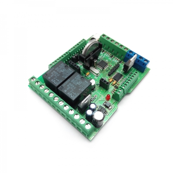
The new Master Kit MP8036multi controller perfectly satisfies all these tasks, on the basis of which we will build the boiler control system.
The algorithm for putting the boiler into operation should be as follows:
1. The initial state (the boiler has been extinguished, it is necessary to light the gas burner). If the temperature according to the sensor "1" is less than the set temperature (temp2), the fan blows the heat exchanger, after a specified time (bp1), power is supplied to the electric ignition of the burner;
2. Check the success of the ignition. If the temperature according to the sensor “1” reaches the set temperature (temp1), the power is removed from the burner, the blower fan continues to work for the set time (bp2), after which it is also turned off;
3. Emergency mode (for some reason, the temperature at the outlet of the boiler becomes higher than normal). If one of the temperature sensors fails or the temperature at sensor “2” reaches the preset alarm, the audible and visual alarm signal is turned on, the burner is powered off, the blower fan continues to work for the set time (bp2), and then also turns off.
Let's agree that in the program the outputs are designated as:
RELAY1 -
RELAY2 fan -
PWM1 burner - accident (sound and light)
Any logical output could be selected as a control channel of the ALARM indication, but since this is an example of the module's operation, a PWM output was selected.
Now you have all the necessary source data in order to easily understand the algorithm of the program, the text of which is given below. The operating time and temperature are indicated conditionally; if necessary, the values must be changed to the required values.
For the convenience of understanding the process, we recommend downloading the program into the module.
PROGRAM TEXT
// RELAY1 - fan
// RELAY2 - burner
// PWM1 - siren (sound and light)
// INPUT1 - error control
// temperature setpoint 1: + 29C / + 30 C
// temperature setpoint 2: +32 C
RESET CONFIGURATIONS
RELE1.REZHIM_PO_UMOLCHANIYU = 1
RELE1.REZHIM1.SOSTOYANIE = OFF
RELE1.REZHIM1.USLOVIE1: INPUT1 = 1
RELE1.REZHIM1.LOGIKA_USLOVY = U1
RELE1.REZHIM2.SOSTOYANIE = ON
RELE1.REZHIM2.USLOVIE1: DT1 multiple unit <28
RELE1.REZHIM2.USLOVIE2: INPUT1 = 0
RELE1.REZHIM2.LOGIKA_USLOVY = y1 and y2
RELE1.REZHIM3.SOSTOYANIE = ON
RELE1.REZHIM3.VREMYA_DEYSTVIYA = 10 (c)
RELE1.REZHIM3.USLOVIE1: DT1 multiple unit> 30
RELE1.REZHIM3.USLOVIE2: dT2> 32
RELE1.REZHIM3 CONDITION3: INPUT1 = 0
RELAY 1. MODE3. CONDITION LOGIC = (U1 OR Y2) AND U3
RELAY1.
MODE 4.STATE = ACTIVATED RELAY1. MODE4. ACTION TIME = 30 (s)
RELAY1. MODE4.
MODE4. A_Terms = U4
RELAY2. MODE_DEFAULT = 1
RELAY2. MODE 1.STATE = DISABLED
RELAY2. MODE 1. CONDITION 1 : DT1> 30
RELAY2. MODE 1. CONDITION 2: DT2> 32
RELAY2. MODE 1
.
RELE2.REZHIM2.SOSTOYANIE = ON
RELE2.REZHIM2.ZADERZHKA = 10 (c)
RELE2.REZHIM2.USLOVIE1: DT1 multiple unit <28
RELE2.REZHIM2.USLOVIE2: INPUT1 = 0
RELE2.REZHIM2.LOGIKA_USLOVY = y1 and y2
SHIM1.REZHIM_PO_UMOLCHANIYU = 1
PWM1 MODE1. FUNCTION = DISCRETE_
OUTPUT PWM1. MODE 1.STATE = 0
PWM1. MODE1. CONDITION1: DT2 <34
PWM1. MODE1. CONDITION2: INPUT1 = 0
PWM1.
MODE1. OD
PWM1. MODE 2. STATE = 1
PWM 1. MODE 2. CONDITION 1 : DT2> 35
PWM 1. MODE 2. CONDITION 2: ENTRANCE 1 = 1
PWM 1. MODE 2. LOGIC_CONTENT = U1 OR Y2
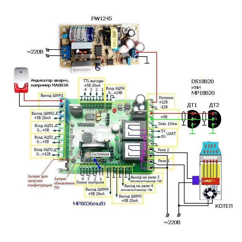
Do not forget to add temperature sensors ДТ1 and ДТ2 according to the instructions according to the instructions according to the instructions according to the instructions in the configuration to the module. Please note that the sensors must be connected in turn.
Connection diagram
Continued ...
In many country houses, a gas boiler is installed, which provides heating of the house and the supply of hot water. Often, these boilers are old-fashioned or very budget ones that do not have a sufficient level of automation. There is a natural desire to modify these boilers and increase comfort and safety when using them.
In a general approximation, the boiler has the following main controls and alarms:
- burner with electric ignition;
- temperature sensor No. 1;
- temperature sensor No. 2;
- fan blowing heat exchanger;
- sound and light alarm emergency mode.
Accordingly, the control controller must support work with two independent temperature sensors, have at least two independent relay outputs, one alarm output - and at the same time have the flexibility of a flexible configuration.
The new Master Kit MP8036multi controller perfectly satisfies all these tasks, on the basis of which we will build the boiler control system.
The algorithm for putting the boiler into operation should be as follows:
1. The initial state (the boiler has been extinguished, it is necessary to light the gas burner). If the temperature according to the sensor "1" is less than the set temperature (temp2), the fan blows the heat exchanger, after a specified time (bp1), power is supplied to the electric ignition of the burner;
2. Check the success of the ignition. If the temperature according to the sensor “1” reaches the set temperature (temp1), the power is removed from the burner, the blower fan continues to work for the set time (bp2), after which it is also turned off;
3. Emergency mode (for some reason, the temperature at the outlet of the boiler becomes higher than normal). If one of the temperature sensors fails or the temperature at sensor “2” reaches the preset alarm, the audible and visual alarm signal is turned on, the burner is powered off, the blower fan continues to work for the set time (bp2), and then also turns off.
Let's agree that in the program the outputs are designated as:
RELAY1 -
RELAY2 fan -
PWM1 burner - accident (sound and light)
Any logical output could be selected as a control channel of the ALARM indication, but since this is an example of the module's operation, a PWM output was selected.
Now you have all the necessary source data in order to easily understand the algorithm of the program, the text of which is given below. The operating time and temperature are indicated conditionally; if necessary, the values must be changed to the required values.
For the convenience of understanding the process, we recommend downloading the program into the module.
PROGRAM TEXT
// RELAY1 - fan
// RELAY2 - burner
// PWM1 - siren (sound and light)
// INPUT1 - error control
// temperature setpoint 1: + 29C / + 30 C
// temperature setpoint 2: +32 C
RESET CONFIGURATIONS
RELE1.REZHIM_PO_UMOLCHANIYU = 1
RELE1.REZHIM1.SOSTOYANIE = OFF
RELE1.REZHIM1.USLOVIE1: INPUT1 = 1
RELE1.REZHIM1.LOGIKA_USLOVY = U1
RELE1.REZHIM2.SOSTOYANIE = ON
RELE1.REZHIM2.USLOVIE1: DT1 multiple unit <28
RELE1.REZHIM2.USLOVIE2: INPUT1 = 0
RELE1.REZHIM2.LOGIKA_USLOVY = y1 and y2
RELE1.REZHIM3.SOSTOYANIE = ON
RELE1.REZHIM3.VREMYA_DEYSTVIYA = 10 (c)
RELE1.REZHIM3.USLOVIE1: DT1 multiple unit> 30
RELE1.REZHIM3.USLOVIE2: dT2> 32
RELE1.REZHIM3 CONDITION3: INPUT1 = 0
RELAY 1. MODE3. CONDITION LOGIC = (U1 OR Y2) AND U3
RELAY1.
MODE 4.STATE = ACTIVATED RELAY1. MODE4. ACTION TIME = 30 (s)
RELAY1. MODE4.
MODE4. A_Terms = U4
RELAY2. MODE_DEFAULT = 1
RELAY2. MODE 1.STATE = DISABLED
RELAY2. MODE 1. CONDITION 1 : DT1> 30
RELAY2. MODE 1. CONDITION 2: DT2> 32
RELAY2. MODE 1
.
RELE2.REZHIM2.SOSTOYANIE = ON
RELE2.REZHIM2.ZADERZHKA = 10 (c)
RELE2.REZHIM2.USLOVIE1: DT1 multiple unit <28
RELE2.REZHIM2.USLOVIE2: INPUT1 = 0
RELE2.REZHIM2.LOGIKA_USLOVY = y1 and y2
SHIM1.REZHIM_PO_UMOLCHANIYU = 1
PWM1 MODE1. FUNCTION = DISCRETE_
OUTPUT PWM1. MODE 1.STATE = 0
PWM1. MODE1. CONDITION1: DT2 <34
PWM1. MODE1. CONDITION2: INPUT1 = 0
PWM1.
MODE1. OD
PWM1. MODE 2. STATE = 1
PWM 1. MODE 2. CONDITION 1 : DT2> 35
PWM 1. MODE 2. CONDITION 2: ENTRANCE 1 = 1
PWM 1. MODE 2. LOGIC_CONTENT = U1 OR Y2
Do not forget to add temperature sensors ДТ1 and ДТ2 according to the instructions according to the instructions according to the instructions according to the instructions in the configuration to the module. Please note that the sensors must be connected in turn.
Connection diagram
Continued ...