Astrotracker: my experience
In order to combine his two favorite hobbies: photography and astronomy, I decided to try myself in astrophotography. Pictures of the Milky Way with huge placers of stars have a very deep impression on me. Moreover, every summer I visit the Caucasus, and the sky there is ideal for observation. For high-quality shooting of the starry sky you can not do without an astrotracker. Why do I need it, I don’t see the need to repeat it, because there have already been several articles on this topic. Therefore, I would just like to share my experience in creating this device, its configuration and use. I got the design from this article, simplified it a bit, and equipped it with my own improvements. Details under the cut.

I must say right away that, unlike SW. kuzmuk(author of the original article) the process of making an astrotracker took me not two evenings, and not even two weeks, but two whole months. But such a long period is associated primarily with the long delivery of some components from China. When creating the tracker, I set myself two main goals: maximum simplicity of design and maximum tracking accuracy with the resulting device.
1. Drive
In the original article, the drive uses a stepper motor with a driver and Arduino as a controller. But since before this project I had no experience with Arduino programming, I decided to use a simple DC motor (DC motor). Moreover, I have met on the Internet a lot of designs of trackers with DPT. I ordered a 5V motor on Ebay, with a built-in gearbox, with a total speed of about 8 rpm. Given a stabilized power supply, I expected to get a constant output speed, although I understood that the speed of rotation of the DCT depends on the load.

Imagine my disappointment. The fact is that even without load, powered by a laboratory source, the engine speed was not stable. In the figure below you can see how the "speed" is floating over time. I did not have an accurate tool for determining speed, so I used the interval measurement method with refinement. The result was not acceptable.

There was no other choice but to use an engine with synchronous speed, which is the 28BYJ-48 shagovik. A cursory study of Arduino showed that there are no difficulties, and the whole program comes down to alternately turning on the four phases of the engine with a certain delay. The speed, as expected, in such a system was very stable.

In addition, the use of Arduino made it possible to fine-tune the speed of rotation, which meant that the requirements for precision manufacturing of the gear mechanism decreased.
2. Swivel mechanism and transmission
I did not consider it necessary to use laser cutting to make the base, because I did not impose any restrictions on the size of the future tracker. On the contrary, the larger the base, the higher the accuracy due to less backlash in the axis. For the base, I took two plywood cutting boards from Auchan. I chose the awnings with a minimum clearance (later the clearance was still compensated by a hammer) and placed on the edges of the base. The greater the distance between the canopies, the more accurate the operation of the mechanism. He bent the hairpin according to the method described in the original article.

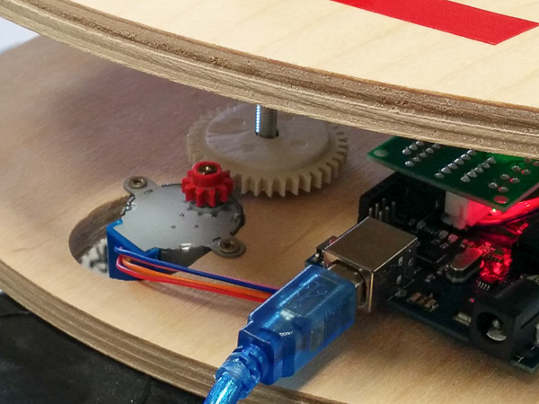
He also did not make gears to order, but took it from an old Soviet moon rover with a gear ratio of ~ 4. In my case, it was 3.8. He put a nut on the hot glue in the big gear.

The final form of transmission:
3. Calculation of rotation speed
Calculation of the required rotation speed of the motor shaft is not difficult, if you understand the basic principles. Everything is based on one equation. For convenience, I used Excel:

4. Calibration
I understood that in the manufacture of perfectly accurate to withstand all the dimensions of the tracker does not work with all desire. There will be an error in any case, so I developed a methodology for its compensation in advance. It consists in laser calibration of the tracker: a laser is mounted on the turning part and shines on a screen located at a known distance from the tracker axis. So, by measuring the time the tracker is turned on and off, you can calculate what path the laser point should go on the screen and correlate it with the actual measured roulette. The farther the screen is and the tracker lasts longer, the more accurate the result.

Admittedly, even without calibration, the tracking error was only about 0.8%. After adjusting the pause time between the switching phases of the step, the error was about 0.2%. The table below shows how the error decreases with increasing pause time.

The program for Arduino was left as simple as possible. All she does is commute the steps of the step with the pause defined above. The rotation starts immediately after power is applied. Also, only one phase is switched at the same time - the motor torque in this case is less (it is already abundant), but the batteries live 2 times longer.
After setting up, I replaced the board with an Arduino Micro, which fit perfectly on the engine driver board, and placed everything in a plastic case. I used PowerBank at 2300 mAh as a power source (enough for ~ 5 hours of tracking).

5. Laser sight
Having some experience in astronomical observations, I realized that the tracker aiming at the North Star would be a big problem. It is unacceptable to expose the axis to the eye, but did not want to install the pole finder because of its cost. Therefore, I decided to make a homemade laser sight. To do this, I ordered here such a green laser with a wavelength of 532 nm and a power of 5 mW. Judging by information on the Internet, his beam should have been clearly visible in the dark.
To be able to fine-tune the direction of the laser beam, I used a larger diameter plastic tube with screw adjustment as a fastener:
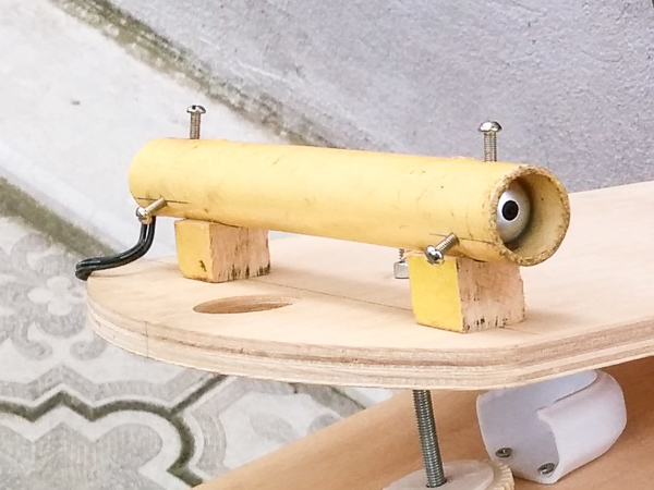
In this case, the process of calibrating the alignment of the laser beam with the tracker axis looked as follows: the distance between the laser axis and the tracker axis is measured, then a circle with a radius equal to changed value. The circle (let's call it a target) is placed at a certain distance from the tracker and the position of the moving part of the tracker is manually changed. If the axes are parallel, then the laser beam must go exactly in a circle. And again: the greater the distance between the tracker and the target, the more accurate the result.
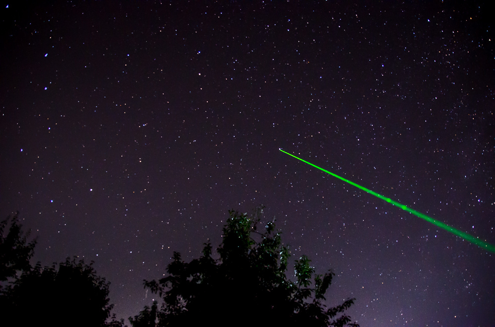
As for the appearance in the dark, I must say, the Chinese did not deceive:
6. Other
For shooting, we used a Nikon D7000 camera with a Sigma 17-50 f2.8 lens. To install it on the tracker, I ordered a 3D head on Ebay, and to avoid shaking when releasing the shutter, I ordered a wired control panel .
The final form of construction: The

laser is powered from the same PowerBank through the toggle switch in the control unit.
Separately, a few words should be said about the tripod. I have a home-made one that can easily cope with a load of several kilograms, but the exact adjustment is clearly not enough. Moreover, it’s exact, rough, in general, is not needed at all, because the polar star is always at one point in the sky. You can initially calculate the length of the legs of the tripod so that it gives the tracker tilt of ~ 45 degrees, and then, with the help of precise adjustment, aim at the star.
The Stellarium virtual planetarium program helps a lot with the preliminary planning of the survey . You can set the coordinates and time and see at what point in the sky at this moment the center of the Milky Way and other objects will be and whether the Moon will interfere.
Also, this site is very useful when choosing a shooting location. It is a map of light pollution. Choose the least lit areas.
7. Results
Photo exposure 5-7 min, aperture 4, ISO 400.

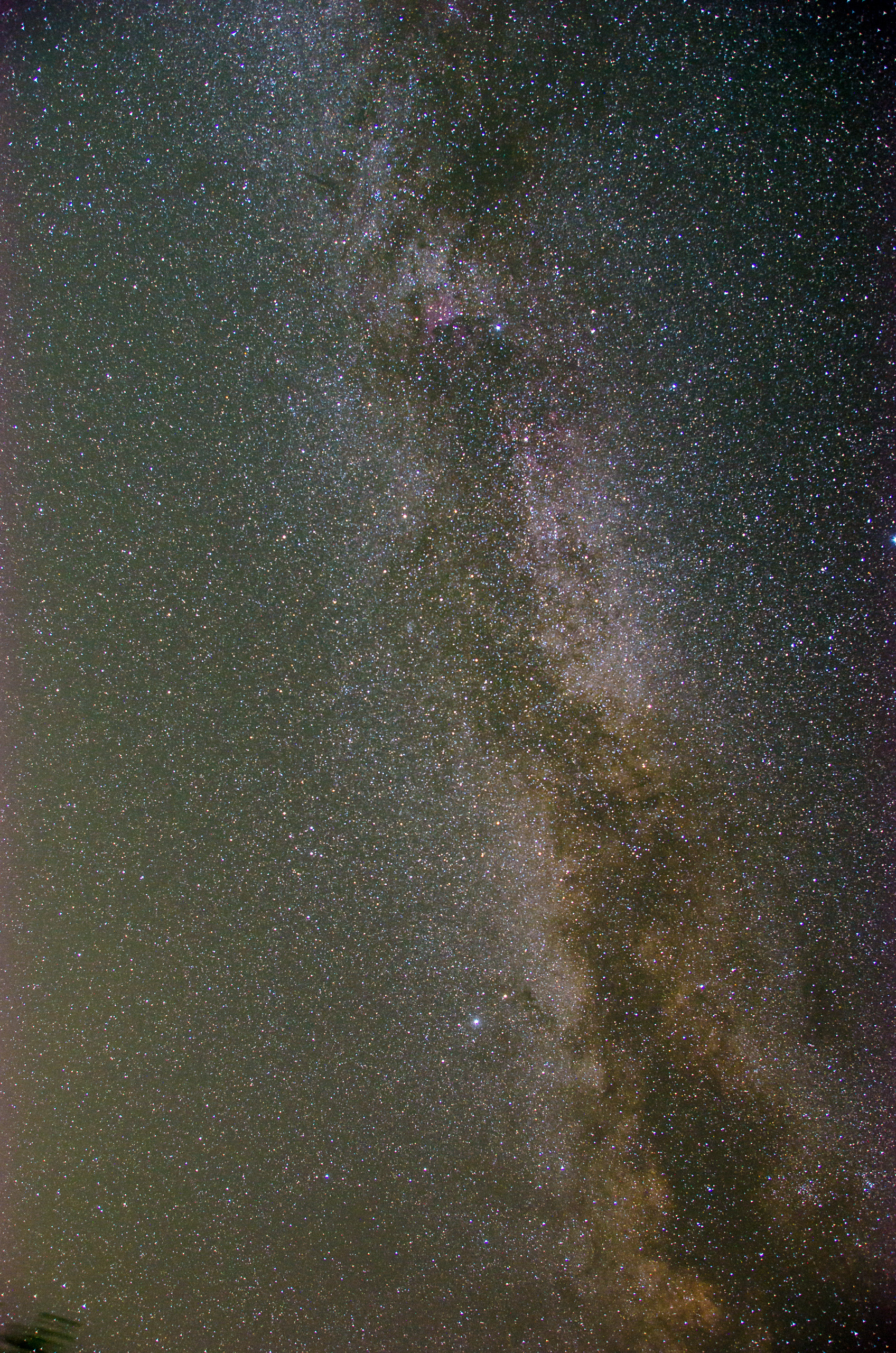
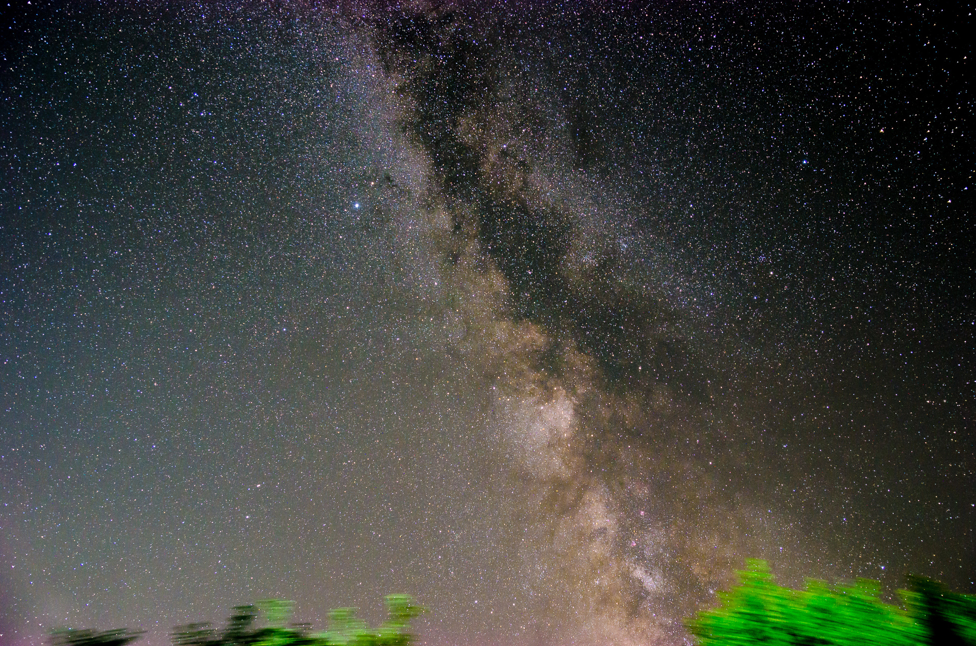
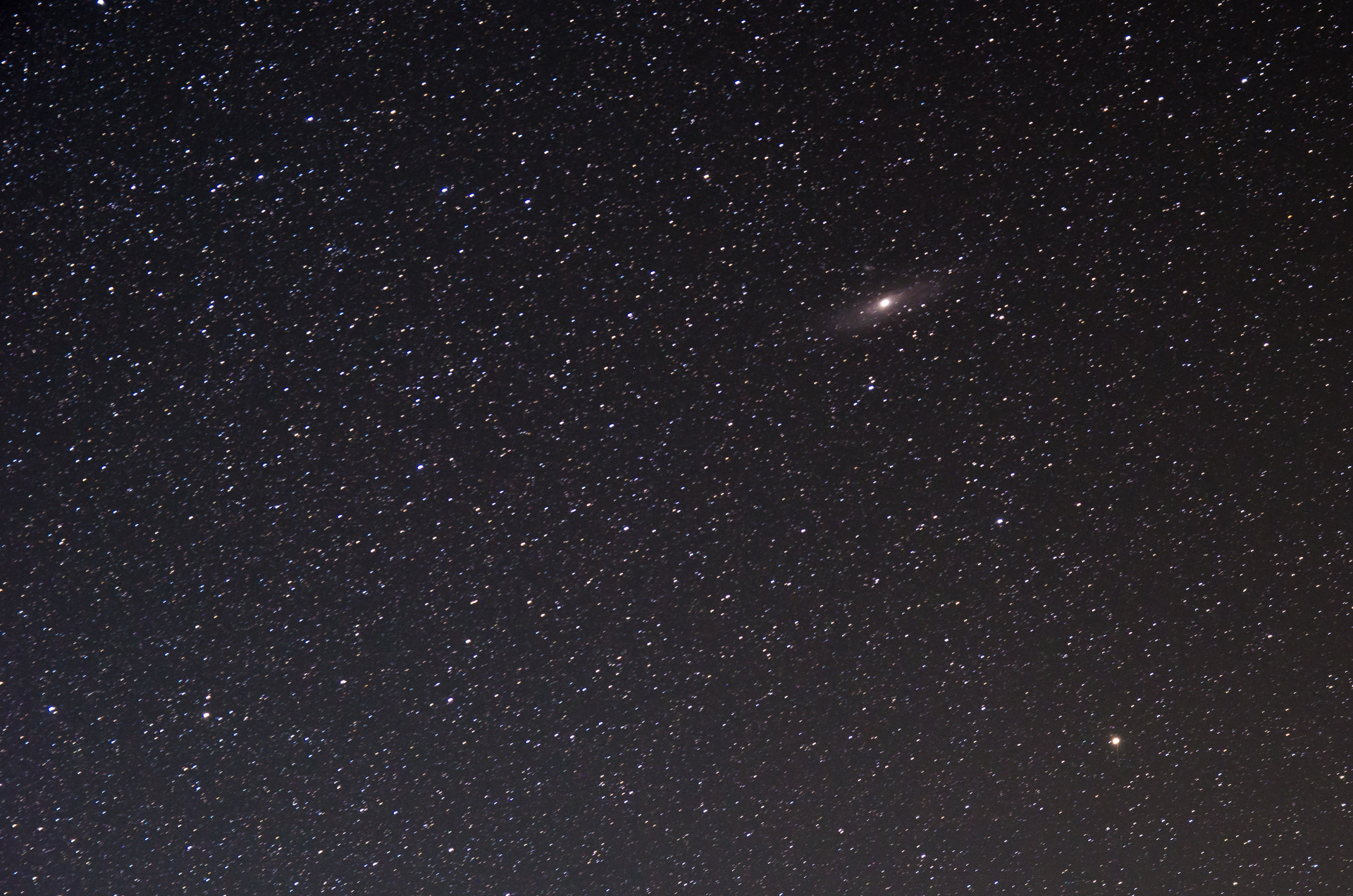
The last photo with the Andromeda Nebula shows a slight blur, but I think this is due to a lost tip to the pole of the world.
The shooting was carried out on a clear night, far from the city flare and in the absence of the moon. Under such conditions, the eyes quickly get used to the darkness and the plane of our galaxy can be seen with the naked eye. The result was more than satisfied. And the process of preparation, observation and shooting itself brings true pleasure.

I must say right away that, unlike SW. kuzmuk(author of the original article) the process of making an astrotracker took me not two evenings, and not even two weeks, but two whole months. But such a long period is associated primarily with the long delivery of some components from China. When creating the tracker, I set myself two main goals: maximum simplicity of design and maximum tracking accuracy with the resulting device.
1. Drive
In the original article, the drive uses a stepper motor with a driver and Arduino as a controller. But since before this project I had no experience with Arduino programming, I decided to use a simple DC motor (DC motor). Moreover, I have met on the Internet a lot of designs of trackers with DPT. I ordered a 5V motor on Ebay, with a built-in gearbox, with a total speed of about 8 rpm. Given a stabilized power supply, I expected to get a constant output speed, although I understood that the speed of rotation of the DCT depends on the load.

Imagine my disappointment. The fact is that even without load, powered by a laboratory source, the engine speed was not stable. In the figure below you can see how the "speed" is floating over time. I did not have an accurate tool for determining speed, so I used the interval measurement method with refinement. The result was not acceptable.
There was no other choice but to use an engine with synchronous speed, which is the 28BYJ-48 shagovik. A cursory study of Arduino showed that there are no difficulties, and the whole program comes down to alternately turning on the four phases of the engine with a certain delay. The speed, as expected, in such a system was very stable.
In addition, the use of Arduino made it possible to fine-tune the speed of rotation, which meant that the requirements for precision manufacturing of the gear mechanism decreased.
2. Swivel mechanism and transmission
I did not consider it necessary to use laser cutting to make the base, because I did not impose any restrictions on the size of the future tracker. On the contrary, the larger the base, the higher the accuracy due to less backlash in the axis. For the base, I took two plywood cutting boards from Auchan. I chose the awnings with a minimum clearance (later the clearance was still compensated by a hammer) and placed on the edges of the base. The greater the distance between the canopies, the more accurate the operation of the mechanism. He bent the hairpin according to the method described in the original article.

He also did not make gears to order, but took it from an old Soviet moon rover with a gear ratio of ~ 4. In my case, it was 3.8. He put a nut on the hot glue in the big gear.

The final form of transmission:

3. Calculation of rotation speed
Calculation of the required rotation speed of the motor shaft is not difficult, if you understand the basic principles. Everything is based on one equation. For convenience, I used Excel:
4. Calibration
I understood that in the manufacture of perfectly accurate to withstand all the dimensions of the tracker does not work with all desire. There will be an error in any case, so I developed a methodology for its compensation in advance. It consists in laser calibration of the tracker: a laser is mounted on the turning part and shines on a screen located at a known distance from the tracker axis. So, by measuring the time the tracker is turned on and off, you can calculate what path the laser point should go on the screen and correlate it with the actual measured roulette. The farther the screen is and the tracker lasts longer, the more accurate the result.

Admittedly, even without calibration, the tracking error was only about 0.8%. After adjusting the pause time between the switching phases of the step, the error was about 0.2%. The table below shows how the error decreases with increasing pause time.
The program for Arduino was left as simple as possible. All she does is commute the steps of the step with the pause defined above. The rotation starts immediately after power is applied. Also, only one phase is switched at the same time - the motor torque in this case is less (it is already abundant), but the batteries live 2 times longer.
Code for Arduino
#define IN1  8
#define IN2  9
#define IN3  10
#define IN4  11
int time_del=5000;     //микросекунд
void setup() {
pinMode(IN1, OUTPUT);
pinMode(IN2, OUTPUT);
pinMode(IN3, OUTPUT);
pinMode(IN4, OUTPUT);
}
void loop() {
digitalWrite(IN1, HIGH);
digitalWrite(IN2, LOW);
digitalWrite(IN3, LOW);
digitalWrite(IN4, LOW);
delayMicroseconds(time_del);
digitalWrite(IN1, LOW);
digitalWrite(IN2, HIGH);
digitalWrite(IN3, LOW);
digitalWrite(IN4, LOW);
delayMicroseconds(time_del);
digitalWrite(IN1, LOW);
digitalWrite(IN2, LOW);
digitalWrite(IN3, HIGH);
digitalWrite(IN4, LOW);
delayMicroseconds(time_del);
digitalWrite(IN1, LOW);
digitalWrite(IN2, LOW);
digitalWrite(IN3, LOW);
digitalWrite(IN4, HIGH);
delayMicroseconds(time_del);
}
After setting up, I replaced the board with an Arduino Micro, which fit perfectly on the engine driver board, and placed everything in a plastic case. I used PowerBank at 2300 mAh as a power source (enough for ~ 5 hours of tracking).

5. Laser sight
Having some experience in astronomical observations, I realized that the tracker aiming at the North Star would be a big problem. It is unacceptable to expose the axis to the eye, but did not want to install the pole finder because of its cost. Therefore, I decided to make a homemade laser sight. To do this, I ordered here such a green laser with a wavelength of 532 nm and a power of 5 mW. Judging by information on the Internet, his beam should have been clearly visible in the dark.
To be able to fine-tune the direction of the laser beam, I used a larger diameter plastic tube with screw adjustment as a fastener:

In this case, the process of calibrating the alignment of the laser beam with the tracker axis looked as follows: the distance between the laser axis and the tracker axis is measured, then a circle with a radius equal to changed value. The circle (let's call it a target) is placed at a certain distance from the tracker and the position of the moving part of the tracker is manually changed. If the axes are parallel, then the laser beam must go exactly in a circle. And again: the greater the distance between the tracker and the target, the more accurate the result.
As for the appearance in the dark, I must say, the Chinese did not deceive:

6. Other
For shooting, we used a Nikon D7000 camera with a Sigma 17-50 f2.8 lens. To install it on the tracker, I ordered a 3D head on Ebay, and to avoid shaking when releasing the shutter, I ordered a wired control panel .
The final form of construction: The

laser is powered from the same PowerBank through the toggle switch in the control unit.
Separately, a few words should be said about the tripod. I have a home-made one that can easily cope with a load of several kilograms, but the exact adjustment is clearly not enough. Moreover, it’s exact, rough, in general, is not needed at all, because the polar star is always at one point in the sky. You can initially calculate the length of the legs of the tripod so that it gives the tracker tilt of ~ 45 degrees, and then, with the help of precise adjustment, aim at the star.
The Stellarium virtual planetarium program helps a lot with the preliminary planning of the survey . You can set the coordinates and time and see at what point in the sky at this moment the center of the Milky Way and other objects will be and whether the Moon will interfere.
Also, this site is very useful when choosing a shooting location. It is a map of light pollution. Choose the least lit areas.
7. Results
Photo exposure 5-7 min, aperture 4, ISO 400.


The last photo with the Andromeda Nebula shows a slight blur, but I think this is due to a lost tip to the pole of the world.
The shooting was carried out on a clear night, far from the city flare and in the absence of the moon. Under such conditions, the eyes quickly get used to the darkness and the plane of our galaxy can be seen with the naked eye. The result was more than satisfied. And the process of preparation, observation and shooting itself brings true pleasure.
