OpenHAB's Wireless Home Air Conditioner Controller via Modbus via RF24Network
After my first article about controlling air conditioning with a controller, a little more than 2 years passed. During this time, the idea of controlling the air conditioner remotely did not leave me and had several rebirths. The main condition was the absence of any wires to the air conditioner.
That is, the control of the controller must be wireless.
Background
The first prototype was the Arduino UNO. She accepted teams on UART and knew how to turn on and off the air conditioner. Because there was little practical sense from the arduinka connected to the working computer, the head was constantly looking for the opportunity to connect the latter to the home server. There were no direct visibility from the server to the culprit of all the puzzles. The maximum is a socket with a LAN on all the same working computer - since it stands almost opposite the air conditioner. An Ethernet shield was not available. But remembering that somewhere in the zashashnik lies a d-link DSL-2500U dsl modem that has not been used for a long time, with just one port on board. The desire to give a second life to the piece of iron led to googling, which, in turn, miraculously led to the article Turning an ADSL modem into an Ethernet shield for Arduino / CraftDuino .
Jumping ahead and skipping the interesting process of creating custom firmware, I still managed to get the modem to listen on the desired port and “forward” the UART through it. Thus, on the home server, I could send a command to turn on / off the port to the local modem address, which will go to the arduino connected to it.
But this article is not about that. The ultimate solution uses Modbus protocol and RF24Network wireless network . And everything is controlled in OpenHAB.
During these two years, I managed to order a lot of all nishtyaks from China and most of them were waiting in the wings. This list included the NRF24L01 + module, bought by a handful for experimentation. And he would lie further somewhere in the closet idle, if one day I had not stumbled upon a series of articles:
from Borich , for which thanks to him!
Thanks to them, I became acquainted with the Modbus protocol. But most importantly, I discovered OpenHAB for myself - what I have been looking for a long time. This prompted me to start implementing long-standing ideas.
Having played around with examples from the articles, I decided to try to separate the controller and server using the ethernet-shield from the modem described above. This solution allowed us to achieve the posed task - the shield and controller were located on the desktop, without using a working computer, at the same time, the shield is always connected to the local network and is accessible from the home server.
But this decision was doomed to failure.
For such a bundle, ModbusRtu over TCP support was required for the control program. Fortunately, the modpoll program mentioned in Arduino & Modbus supported one. There was no limit to joy - polling the controller in such a bundle at the local modem address 192.168.1.110 on port 3000 worked successfully!
You need to configure the connection in OpenHAB. But, unfortunately, Modbus Binding does not know “RTU over TCP”. At that moment, this did not stop me - it was decided to finish the ModbusRtu library for arduino with the aim of changing the packet format to TCP. The differences turned out to be very small and the controller is already working in conjunction OpenHAB- (ethernet) -modem- (UART) -controller.
It would seem that what else is needed? But the problem was in the amount of Item in the configuration. During testing, I configured only 1 Item and its poll was successful. But it was worth adding a few more - immediately there were errors during the transfer. The problem, it seemed to me, was the TCP connector asynchrony on the Modbus Binding side. Those. my shield from the modem was not designed for several simultaneous connections and the data was mixed.
My attempts to modify Modbus Binding to be able to synchronize Item’s polls with the same host-port-slaveID did not improve the situation.
The decisive factor to put an end to this decision was that it was not scalable. If you want to add another controller to the common system, it will require one more such shield from the modem. Yes, and wireless did not smell here, although it met the conditions of the task.
You need to configure the connection in OpenHAB. But, unfortunately, Modbus Binding does not know “RTU over TCP”. At that moment, this did not stop me - it was decided to finish the ModbusRtu library for arduino with the aim of changing the packet format to TCP. The differences turned out to be very small and the controller is already working in conjunction OpenHAB- (ethernet) -modem- (UART) -controller.
It would seem that what else is needed? But the problem was in the amount of Item in the configuration. During testing, I configured only 1 Item and its poll was successful. But it was worth adding a few more - immediately there were errors during the transfer. The problem, it seemed to me, was the TCP connector asynchrony on the Modbus Binding side. Those. my shield from the modem was not designed for several simultaneous connections and the data was mixed.
My attempts to modify Modbus Binding to be able to synchronize Item’s polls with the same host-port-slaveID did not improve the situation.
The decisive factor to put an end to this decision was that it was not scalable. If you want to add another controller to the common system, it will require one more such shield from the modem. Yes, and wireless did not smell here, although it met the conditions of the task.
Idea
And then I finally established myself that I need to make a controller that is accessible by air. The NRF24L01 + modules should not disappear! .. True, this required at least two controllers - one performs a direct role, the second plays the role of a router. The second should be connected to the server and it is through it that wireless communication with the others is carried out. When connecting to it, we specify the ID of the subordinate to whom the package is intended. It turns out that many slaves are available on one serial port. Yes - this is a Modbus-based wireless network.
Modbus, by the way, made it possible to build a network with one master - many subordinates. And the RF24Network library - to make everything wireless, and even with automatic routing between network nodes.
Library Development for Arduino
To implement such a solution, it took quite a bit to modify the Modbus-Master-Slave-for-Arduino library to be able to inherit from it and overload a couple of methods. My implementation is also updated (library.properties is added, the library file is divided into header and body) for the latest Arduino IDE 1.6.5.
The Modbus-over-RF24Network-for-Arduino library allows you to implement two possible behaviors - Proxy and Slave. Example ModbusRF24Proxy is actually an implementation of a “router” and does not require any modifications other than setting the necessary pins.
Modbus ExampleRF24Proxy
#include
#include
#include
#include
#include
#define stlPin  13  // номер выхода индикатора работы (расположен на плате Arduino)
// nRF24L01(+) radio attached using Getting Started board
RF24 radio(9, 10);
// Network uses that radio
RF24Network network(radio);
// Address of our node
const uint16_t this_node = 0;
//Задаём последовательный порт, выход управления TX
ModbusRF24 proxy(network, 0, 0);
int8_t state = 0;
unsigned long tempus;
void setup() {
    // настраиваем входы и выходы
    io_setup();
    // настраиваем последовательный порт ведомого
    proxy.begin(57600);
    SPI.begin();
    radio.begin();
    network.begin(/*channel*/ 90, /*node address*/ this_node);
    // зажигаем светодиод на 100 мс
    tempus = millis() + 100;
    digitalWrite(stlPin, HIGH);
}
void io_setup() {
    digitalWrite(stlPin, HIGH);
    pinMode(stlPin, OUTPUT);
}
void loop() {
    // Pump the network regularly
    network.update();
    // обработка сообщений
    state = proxy.proxy();
    // если получили пакет без ошибок - зажигаем светодиод на 50 мс
    if (state > 4) {
        tempus = millis() + 50;
        digitalWrite(stlPin, HIGH);
    }
    if (millis() > tempus) digitalWrite(stlPin, LOW);
}
A router or proxy uses a special constructor format:
//Задаём последовательный порт, выход управления TX
ModbusRF24 proxy(network, 0, 0);
and function
proxy.proxy();
to process incoming packets on the serial port, send them to the RF24Network, receive a response from the network, send the result back to the serial port.
In this implementation, the proxy has an RF24Network address of zero:
// Address of our node
const uint16_t this_node = 0;
- i.e. this is the root device of the network. If necessary, the position in the topology of the proxy controller can be changed.
Modbus Example RF24Slave
implements an example from Arduino & Modbus :
#include
#include
#include
#include
#include
#define ID   1      // адрес ведомого
#define btnPin  2   // номер входа, подключенный к кнопке
#define ledPin  7  // номер выхода светодиода
// nRF24L01(+) radio attached using Getting Started board
RF24 radio(9, 10);
// Network uses that radio
RF24Network network(radio);
// Address of our node
const uint16_t this_node = ID;
//Задаём ведомому адрес
ModbusRF24 slave(network, ID);
// массив данных modbus
uint16_t au16data[11];
void io_setup() {
    digitalWrite(ledPin, LOW);
    pinMode(ledPin, OUTPUT);
    pinMode(btnPin, INPUT);
}
void io_poll() {
    //Копируем Coil[1] в Discrete[0]
    au16data[0] = au16data[1];
    //Выводим значение регистра 1.3 на светодиод
    digitalWrite(ledPin, bitRead(au16data[1], 3));
    //Сохраняем состояние кнопки в регистр 0.3
    bitWrite(au16data[0], 3, digitalRead(btnPin));
    //Копируем Holding[5,6,7] в Input[2,3,4]
    au16data[2] = au16data[5];
    au16data[3] = au16data[6];
    au16data[4] = au16data[7];
    //Сохраняем в регистры отладочную информацию
    au16data[8] = slave.getInCnt();
    au16data[9] = slave.getOutCnt();
    au16data[10] = slave.getErrCnt();
}
void setup() {
    // настраиваем входы и выходы
    io_setup();
    Serial.begin(57600);
    Serial.println("RF24Network/examples/modbus_slave/");
    SPI.begin();
    radio.begin();
    network.begin(/*channel*/ 90, /*node address*/ this_node);
}
void loop() {
    // Pump the network regularly
    network.update();
    if (network.available()) {
        slave.poll(au16data, 11);
    }
    //обновляем данные в регистрах Modbus и в пользовательской программе
    io_poll();
}
The constructor in this case is already different:
//Задаём ведомому адрес
ModbusRF24 slave(network, ID);
Modbus Register Structure
After the first successful attempts to control the air conditioner with the ability to only turn on and off my appetite only increased. Now this was not enough already, and since I have OpenHAB functionality in my mobile application, it should do as a minimum all the functionality of the native control panel.
This means here is a list of features at least:
- current status indication
- turning on and off the air conditioner, individual modes (O 2 , ionization, quiet mode);
- selection of the current mode (auto, heating, cooling, drainage, fan);
- indication of temperature and fan speed for each mode. For fan mode, only speed;
- vertical curtain setting (auto, 0 °, 15 °, 30 °, 45 °, 60 °);
- horizontal curtain setting (auto, "| |", "/ /", "/ |", "| \", "\ \");
- time setting (hour, minute);
- on timer setting;
- off timer setting;
- setting on time (hour, minute);
- shutdown time setting (hour, minute);
During the development process, the structure of the registers has changed many times with me. The current version is below under the spoiler.
Modbus Registers
| Type | Byte | Bit | Name | Description |
|---|---|---|---|---|
| Bit ro | 0 | 0 | CFG_OXYGEN | 1 - There is an oxygen mode |
| Bit ro | 1 | CFG_ION | 1 - There is an ionization mode | |
| Bit ro | 2 | CFG_QUIET | 1 - There is a silent mode | |
| Bit ro | 3 | CFG_TIMER | 1 - There is on / off according to the time schedule | |
| Bit ro | 4 | CFG_DELAY | 1 - There is a delayed on / off | |
| Bit ro | 5 | CFG_SWING | 1 - There is a curtain control | |
| Bit ro | 6 | CFG_SWINGH | 1 - There is a horizontal curtain control | |
| Bit ro | 7 | CFG_SWINGV | 1 - There is a vertical curtain control | |
| Bit ro | 8 | CFG_CLOCK | 1 - There is a clock | |
| Bit ro | 9 | |||
| Bit ro | 10 | |||
| Bit ro | eleven | CFG_AUTO | 1 - There is an AUTO mode | |
| Bit ro | 12 | CFG_COOL | 1 - There is a COOL mode | |
| Bit ro | thirteen | CFG_HEAT | 1 - There is a HEAT mode | |
| Bit ro | 14 | CFG_DRY | 1 - There is a DRY mode | |
| Bit ro | fifteen | CFG_FAN | 1 - There is a FAN mode | |
| Integer ro | 1 | CFG_TEMP | Min and max. Temperature: Min + Max * 256 | |
| Integer ro | 2 | CFG_FAN_SPEED | Max FAN Speed | |
| Bit ro | 3 | 0 | STATE_POWER | Air conditioning: 0 - off, 1 - on |
| Bit ro | 1 | STATE_OXYGEN | Oxygen: 0 - off, 1 - on | |
| Bit ro | 2 | STATE_ION | Ionization: 0 - off, 1 - on | |
| Bit ro | 3 | STATE_QUIET | Quiet: 0 - off, 1 - on | |
| Bit ro | 4 | STATE_TIMER | Timer: 0 - off, 1 - on | |
| Bit rw | 8 | CONTROL_POWER | ||
| Bit rw | 9 | CONTROL_OXYGEN | ||
| Bit rw | 10 | CONTROL_ION | ||
| Bit rw | eleven | CONTROL_QUIET | ||
| Integer ro | 4 | RTC_HR_MI | 0x1308 | |
| Integer RW | 5 | RTCW_HR_MI | 0x1308 | |
| Integer ro | 6 | TEMPERATURE1 | Ambient temperature. INT16 hundredths of a degree | |
| Integer ro | 7 | TEMPERATURE2 | Nozzle temperature. INT16 hundredths of a degree | |
| Bit rw | 8 | 0 | MODE_AUTO | |
| Bit rw | 1 | MODE_COOL | ||
| Bit rw | 2 | MODE_HEAT | ||
| Bit rw | 3 | MODE_DRY | ||
| Bit rw | 4 | MODE_FAN | ||
| Integer RW | 9 | TEMP_AUTO | AUTO temperature | |
| Integer RW | 10 | TEMP_COOL | COOL Temperature | |
| Integer RW | eleven | TEMP_HEAT | HEAT temperature | |
| Integer RW | 12 | TEMP_DRY | DRY temperature | |
| Integer RW | thirteen | FAN_AUTO | Speed AUTO. 0: Auto | |
| Integer RW | 14 | FAN_COOL | Cool speed. 0: Auto | |
| Integer RW | fifteen | FAN_HEAT | HEAT speed. 0: Auto | |
| Integer RW | 16 | FAN_DRY | DRY speed. 0: Auto | |
| Integer RW | 17 | FAN_SPEED | FAN speed. 0: Auto | |
| Bit rw | 18 | 0 | SWING_AUTO | Auto rotation vertical |
| Bit rw | 1 | SWINGV_0 | Vertical curtain angle 0 ° | |
| Bit rw | 2 | SWINGV_15 | Vertical blind angle 15 ° | |
| Bit rw | 3 | SWINGV_30 | Vertical curtain angle 30 ° | |
| Bit rw | 4 | SWINGV_45 | Vertical curtain angle 45 ° | |
| Bit rw | 5 | SWINGV_60 | Vertical curtain angle 60 ° | |
| Bit rw | 19 | 0 | SWINGH_AUTO | Horizontal auto rotation |
| Bit rw | 1 | SWINGH_VV | Horizontal curtain | | | |
| Bit rw | 2 | SWINGH_LL | Horizontal curtain / / | |
| Bit rw | 3 | SWINGH_LV | Horizontal curtain / | | |
| Bit rw | 4 | SWINGH_VR | Horizontal curtain | \ | |
| Bit rw | 5 | SWINGH_RR | Horizontal curtain | |
| Bit rw | 20 | 0 | TIMER_ON | |
| Bit rw | 1 | TIMER_OFF | ||
| Integer RW | 21 | TIME_ON_HOUR | Inclusion hour | |
| Integer RW | 22 | TIME_ON_MINUTE | Minute of inclusion | |
| Integer RW | 23 | TIME_OFF_HOUR | Shutdown Hour | |
| Integer RW | 24 | TIME_OFF_MINUTE | Minute off | |
| Integer RW | 25 | DS18B20_ENV | Address. Environment | |
| Integer RW | 26 | DS18B20_NOZ | Address. Nozzle |
The registers are organized in such a way that the entire data array is initialized from the EEPROM when the controller starts.
The first 3 registers (CFG_ *) contain the configuration of features, they never change and are initialized by the EEPROM firmware.
Registers 3-7 always display the current state of the controller. The high bits of register 3 are used to change state. Their changes initiate the on / off of the air conditioner and special modes. After the command is executed, the low-order bits of this register are copied to the high-order ones.
Register 4 contains the current controller time, which is read from RTC. The value is saved in BCD format, so that when the register is displayed in hexadecimal notation, the time is read as is - 12:34 is 0x1234.
Register 5 is used to change the RTC time.
Registers 6-7 contain the temperature from the DS18B20 sensors. The value contains a signed integer and is equal to T * 100, i.e. 25.67 ° C = 2567. A maximum of 2 sensors is provided, but the number can be easily changed by expanding the register table to store the addresses of the sensors and their temperatures.
The last 2 bytes of the sensor address are stored in registers 25-26. When changing sensors, reset the corresponding address register. When a new sensor is detected, its address is checked for presence in registers 25-26. If the address is in the table, the temperature value of the sensor is entered in the corresponding register 6-7. If the address is not in the table and the table has zero cells, the current sensor address is written in a free cell.
Registers 8-26, when modified by the user, are saved in the EEPROM.
Glands
The hardware consists of the following components:
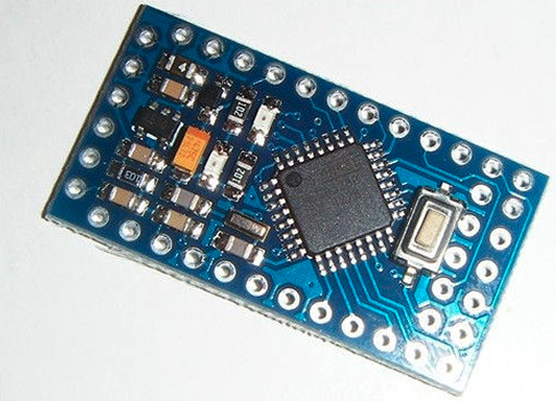
- Arduino Pro Mini. Chinese version
- NRF24L01 + - 2.4GHz Wireless Module
- LM1117-3.3 - 3.3V stabilizer for NRF24L01 +
- DS1302 - RTC
- quartz 32768 kHz for RTC
- DS18B20 - temperature sensor. 2 pcs
- Small things - optocouplers, resistors, capacitor
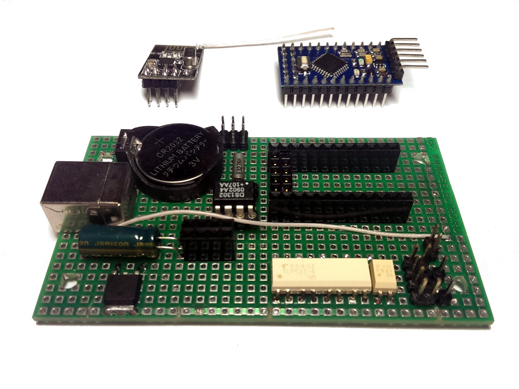
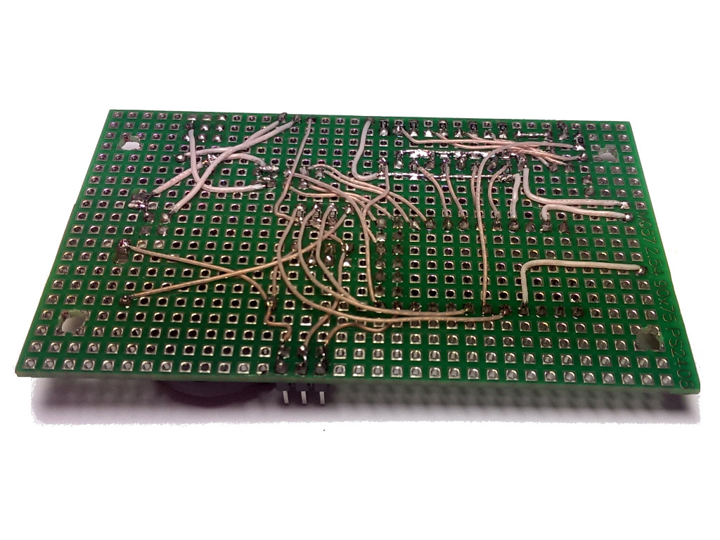
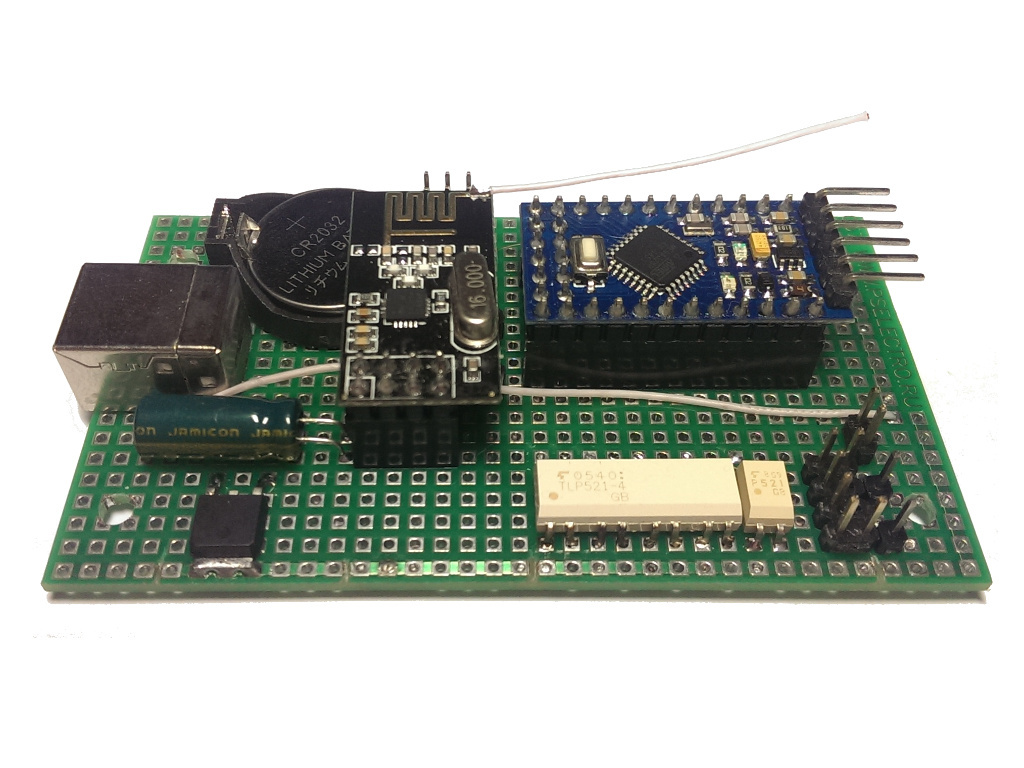
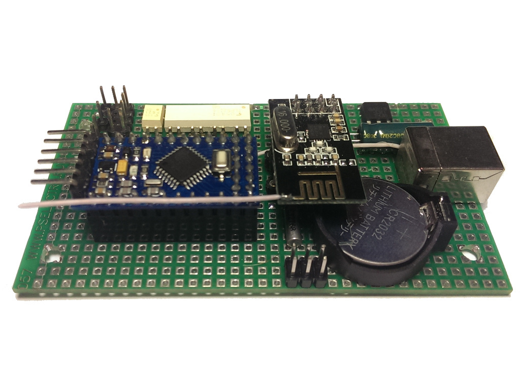
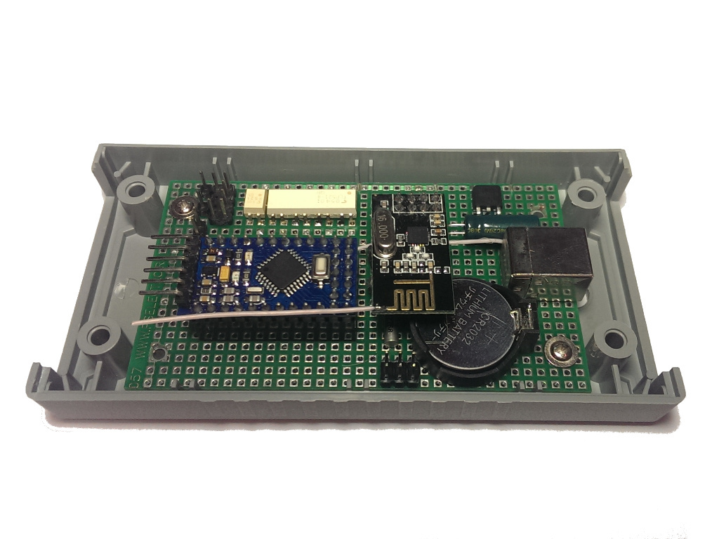
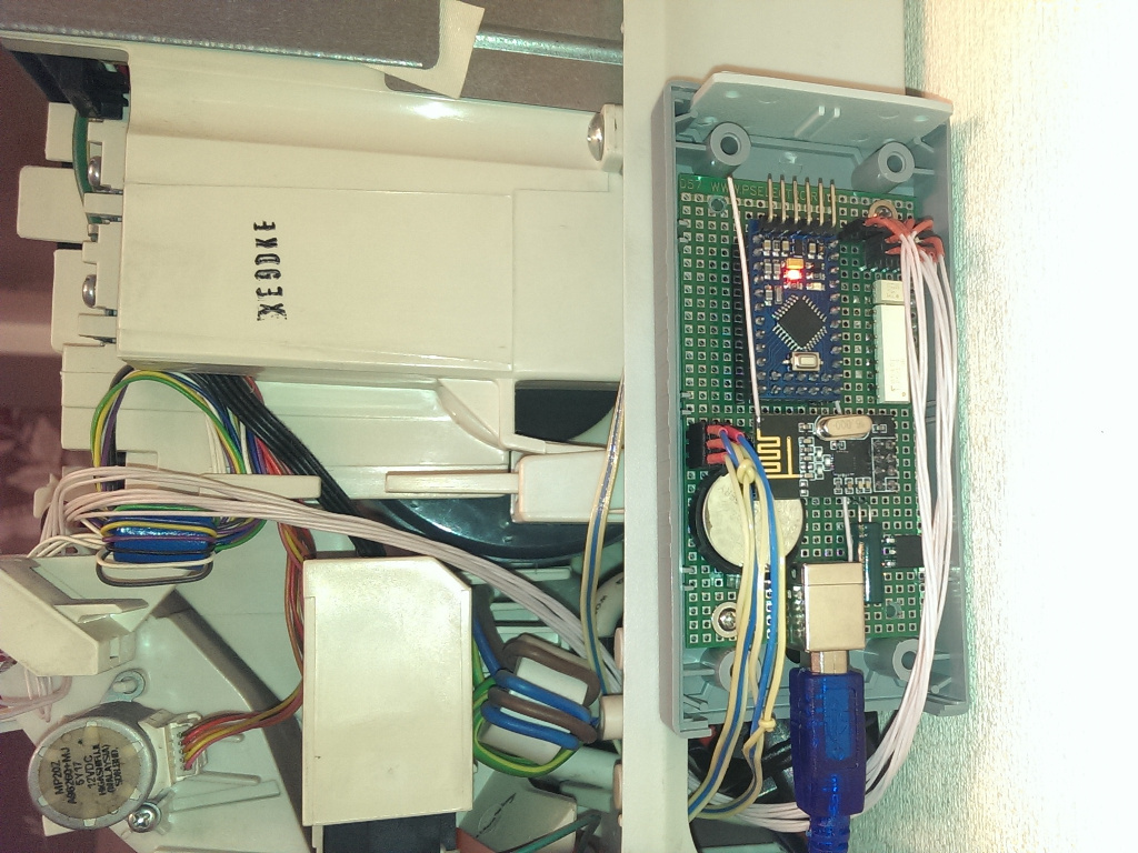
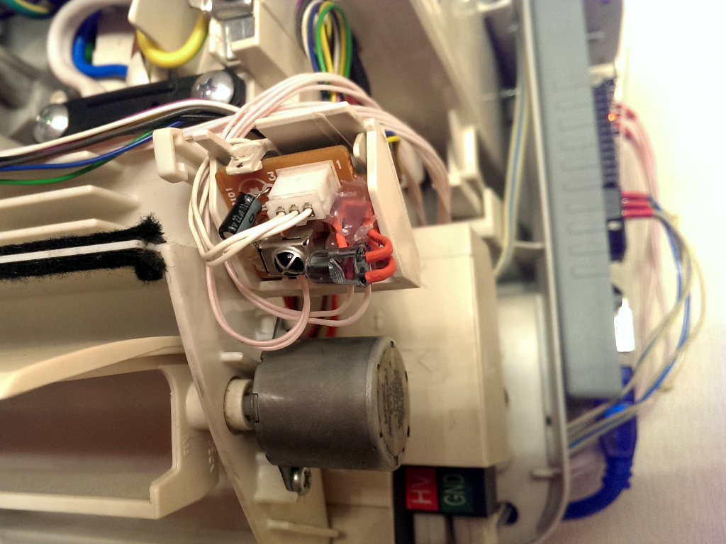
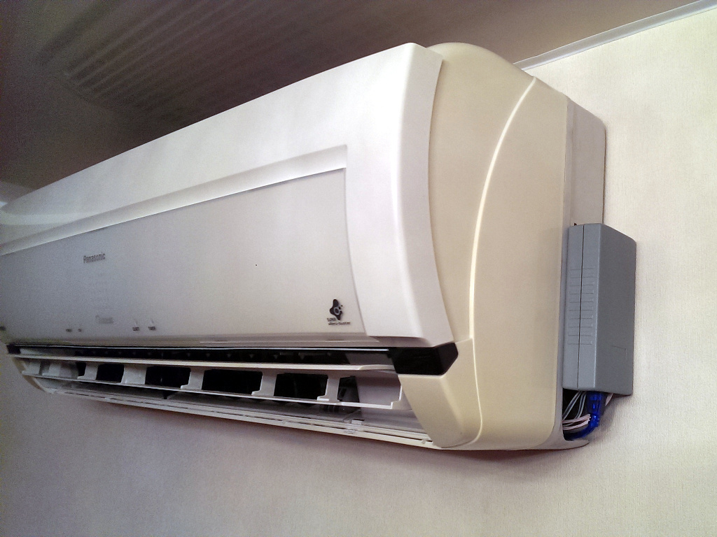
Feedback with the air conditioner is realized by connecting optocouplers to the corresponding LEDs. Thus, galvanic isolation with the electric circuit of the air conditioner is ensured. The current of the inputs for the optocouplers was experimentally selected using resistors so that the output of the optocoupler opens and the brightness of the main LED on the air conditioner does not drop.
An IR LED was installed next to the IR receiver of the air conditioner.
The controller is powered by mini-USB charging from some kind of Chinese miracle. Chinese mains voltage contacts were removed from the charging case, wires were removed. Charging itself settled in the bowels of the air conditioner case, connected to input 220 in parallel with it. The controller connects to charging with a regular USB AB cable.
The “router” controller is based on the Arduino Mega2560 and NRF24L01 + with a separate LM1117-3.3. In addition to a separate 3.3 power supply, an electrolyte is connected to the wireless module (I found it at 470uf * 16v) on the power legs. As you know, the internal Mega2560 3.3V power bus is very noisy and the module refused to transmit data, although it answered correctly. But even with a separate power supply without a capacitor, the connection was very unstable.
So that the mega2560 is not reset when opening the port via USB, a 10μf electrolyte is connected to the reset pin.
Openhab
The Arduino & OpenHAB article describes a feature of the Modbus Binding plug-in, that with each poll of the controller, the plug-in sends an event to the bus, even if nothing has changed. I followed suit and finalized the plugin.
Modbus Binding Plugin Configuration
#Состояние
modbus:serial.ac_hall_state.connection=/dev/ttyACM0:57600:8:none:1:rtu
modbus:serial.ac_hall_state.id=1
modbus:serial.ac_hall_state.start=48
modbus:serial.ac_hall_state.length=5
modbus:serial.ac_hall_state.type=discrete
#Управление
modbus:serial.ac_hall_power.connection=/dev/ttyACM0:57600:8:none:1:rtu
modbus:serial.ac_hall_power.id=1
modbus:serial.ac_hall_power.start=56
modbus:serial.ac_hall_power.length=4
modbus:serial.ac_hall_power.type=coil
#Часы
modbus:serial.ac_hall_rtc.connection=/dev/ttyACM0:57600:8:none:1:rtu
modbus:serial.ac_hall_rtc.id=1
modbus:serial.ac_hall_rtc.start=4
modbus:serial.ac_hall_rtc.length=1
modbus:serial.ac_hall_rtc.type=holding
#Температура датчики
modbus:serial.ac_hall_temperature.connection=/dev/ttyACM0:57600:8:none:1:rtu
modbus:serial.ac_hall_temperature.id=1
modbus:serial.ac_hall_temperature.start=6
modbus:serial.ac_hall_temperature.length=2
modbus:serial.ac_hall_temperature.type=holding
modbus:serial.ac_hall_temperature.valuetype=int16
#Режим
modbus:serial.ac_hall_mode.connection=/dev/ttyACM0:57600:8:none:1:rtu
modbus:serial.ac_hall_mode.id=1
modbus:serial.ac_hall_mode.start=8
modbus:serial.ac_hall_mode.length=1
modbus:serial.ac_hall_mode.type=holding
#температура режима
modbus:serial.ac_hall_temp.connection=/dev/ttyACM0:57600:8:none:1:rtu
modbus:serial.ac_hall_temp.id=1
modbus:serial.ac_hall_temp.start=9
modbus:serial.ac_hall_temp.length=4
modbus:serial.ac_hall_temp.type=holding
#Скорость режима
modbus:serial.ac_hall_fan.connection=/dev/ttyACM0:57600:8:none:1:rtu
modbus:serial.ac_hall_fan.id=1
modbus:serial.ac_hall_fan.start=13
modbus:serial.ac_hall_fan.length=5
modbus:serial.ac_hall_fan.type=holding
#Шторки
modbus:serial.ac_hall_swing.connection=/dev/ttyACM0:57600:8:none:1:rtu
modbus:serial.ac_hall_swing.id=1
modbus:serial.ac_hall_swing.start=18
modbus:serial.ac_hall_swing.length=2
modbus:serial.ac_hall_swing.type=holding
#Таймеры
modbus:serial.ac_hall_timer.connection=/dev/ttyACM0:57600:8:none:1:rtu
modbus:serial.ac_hall_timer.id=1
modbus:serial.ac_hall_timer.start=320
modbus:serial.ac_hall_timer.length=2
modbus:serial.ac_hall_timer.type=coil
#Время таймеров
modbus:serial.ac_hall_timer_time.connection=/dev/ttyACM0:57600:8:none:1:rtu
modbus:serial.ac_hall_timer_time.id=1
modbus:serial.ac_hall_timer_time.start=21
modbus:serial.ac_hall_timer_time.length=4
modbus:serial.ac_hall_timer_time.type=holding
#Адреса датчиков DS18B20
modbus:serial.ac_hall_ds18b20.connection=/dev/ttyACM0:57600:8:none:1:rtu
modbus:serial.ac_hall_ds18b20.id=1
modbus:serial.ac_hall_ds18b20.start=25
modbus:serial.ac_hall_ds18b20.length=2
modbus:serial.ac_hall_ds18b20.type=holding
modbus:serial.ac_hall_state.connection=/dev/ttyACM0:57600:8:none:1:rtu
modbus:serial.ac_hall_state.id=1
modbus:serial.ac_hall_state.start=48
modbus:serial.ac_hall_state.length=5
modbus:serial.ac_hall_state.type=discrete
#Управление
modbus:serial.ac_hall_power.connection=/dev/ttyACM0:57600:8:none:1:rtu
modbus:serial.ac_hall_power.id=1
modbus:serial.ac_hall_power.start=56
modbus:serial.ac_hall_power.length=4
modbus:serial.ac_hall_power.type=coil
#Часы
modbus:serial.ac_hall_rtc.connection=/dev/ttyACM0:57600:8:none:1:rtu
modbus:serial.ac_hall_rtc.id=1
modbus:serial.ac_hall_rtc.start=4
modbus:serial.ac_hall_rtc.length=1
modbus:serial.ac_hall_rtc.type=holding
#Температура датчики
modbus:serial.ac_hall_temperature.connection=/dev/ttyACM0:57600:8:none:1:rtu
modbus:serial.ac_hall_temperature.id=1
modbus:serial.ac_hall_temperature.start=6
modbus:serial.ac_hall_temperature.length=2
modbus:serial.ac_hall_temperature.type=holding
modbus:serial.ac_hall_temperature.valuetype=int16
#Режим
modbus:serial.ac_hall_mode.connection=/dev/ttyACM0:57600:8:none:1:rtu
modbus:serial.ac_hall_mode.id=1
modbus:serial.ac_hall_mode.start=8
modbus:serial.ac_hall_mode.length=1
modbus:serial.ac_hall_mode.type=holding
#температура режима
modbus:serial.ac_hall_temp.connection=/dev/ttyACM0:57600:8:none:1:rtu
modbus:serial.ac_hall_temp.id=1
modbus:serial.ac_hall_temp.start=9
modbus:serial.ac_hall_temp.length=4
modbus:serial.ac_hall_temp.type=holding
#Скорость режима
modbus:serial.ac_hall_fan.connection=/dev/ttyACM0:57600:8:none:1:rtu
modbus:serial.ac_hall_fan.id=1
modbus:serial.ac_hall_fan.start=13
modbus:serial.ac_hall_fan.length=5
modbus:serial.ac_hall_fan.type=holding
#Шторки
modbus:serial.ac_hall_swing.connection=/dev/ttyACM0:57600:8:none:1:rtu
modbus:serial.ac_hall_swing.id=1
modbus:serial.ac_hall_swing.start=18
modbus:serial.ac_hall_swing.length=2
modbus:serial.ac_hall_swing.type=holding
#Таймеры
modbus:serial.ac_hall_timer.connection=/dev/ttyACM0:57600:8:none:1:rtu
modbus:serial.ac_hall_timer.id=1
modbus:serial.ac_hall_timer.start=320
modbus:serial.ac_hall_timer.length=2
modbus:serial.ac_hall_timer.type=coil
#Время таймеров
modbus:serial.ac_hall_timer_time.connection=/dev/ttyACM0:57600:8:none:1:rtu
modbus:serial.ac_hall_timer_time.id=1
modbus:serial.ac_hall_timer_time.start=21
modbus:serial.ac_hall_timer_time.length=4
modbus:serial.ac_hall_timer_time.type=holding
#Адреса датчиков DS18B20
modbus:serial.ac_hall_ds18b20.connection=/dev/ttyACM0:57600:8:none:1:rtu
modbus:serial.ac_hall_ds18b20.id=1
modbus:serial.ac_hall_ds18b20.start=25
modbus:serial.ac_hall_ds18b20.length=2
modbus:serial.ac_hall_ds18b20.type=holding
Настройки items
Contact AC_HALL_STATE_POWER             "AC_HALL_STATE_POWER [MAP(air_cond.map):%s]"    (){modbus="ac_hall_state:0"}
Contact AC_HALL_STATE_OXYGEN            "AC_HALL_STATE_OXYGEN [MAP(air_cond.map):%s]"   (){modbus="ac_hall_state:1"}
Contact AC_HALL_STATE_ION               "AC_HALL_STATE_ION [MAP(air_cond.map):%s]"      (){modbus="ac_hall_state:2"}
Contact AC_HALL_STATE_QUIET             "AC_HALL_STATE_QUIET [MAP(air_cond.map):%s]"    (){modbus="ac_hall_state:3"}
Contact AC_HALL_STATE_TIMER             "Таймер[MAP(air_cond.map):%s]"                  (){modbus="ac_hall_state:4"}
Switch  AC_HALL_CONTROL_POWER           "Кондиционер"                          (){modbus="ac_hall_power:0"}
Switch  AC_HALL_CONTROL_OXYGEN          "Генератор O2"                                  (){modbus="ac_hall_power:1"}
Switch  AC_HALL_CONTROL_ION             "Ионизация"                                     (){modbus="ac_hall_power:2"}
Switch  AC_HALL_CONTROL_QUIET           "Тихий режим"                                   (){modbus="ac_hall_power:3"}
Number  AC_HALL_RTC                     "RTC[%x]"                                       (){modbus="ac_hall_rtc:0"}
String  AC_HALL_RTC_S                   "Время контроллера[%s]"                  ()
Group   gAC_HALL_TEMPERATURE            "Living Room temp"
Number  AC_HALL_TEMPERATURE_ENV         "Комната[%d]"                                   (){modbus="ac_hall_temperature:0"}
Number  AC_HALL_TEMPERATURE_NOZ         "Поток[%d]"                                     (){modbus="ac_hall_temperature:1"}
Number  AC_HALL_TEMPERATURE_ENVF        "Комната [%.2f °C]"                (gAC_HALL_TEMPERATURE)
Number  AC_HALL_TEMPERATURE_NOZF        "Поток [%.2f °C]"                  (gAC_HALL_TEMPERATURE)
Number  AC_HALL_DS18B20_ENV             "ENV[%x]"                                       (){modbus="ac_hall_ds18b20:0"}
Number  AC_HALL_DS18B20_NOZ             "NOZZLES[%x]"                                   (){modbus="ac_hall_ds18b20:1"}
Number  AC_HALL_MODE                    ""                                              (){modbus="ac_hall_mode:0"}
Number  AC_HALL_TEMP_AUTO               "Температура[%d °C]"               (){modbus="ac_hall_temp:0"}
Number  AC_HALL_TEMP_COOL               "Температура[%d °C]"               (){modbus="ac_hall_temp:1"}
Number  AC_HALL_TEMP_HEAT               "Температура[%d °C]"               (){modbus="ac_hall_temp:2"}
Number  AC_HALL_TEMP_DRY                "Температура[%d °C]"               (){modbus="ac_hall_temp:3"}
Number  AC_HALL_FAN_AUTO                "Скорость[%d]"                                  (){modbus="ac_hall_fan:0"}
Number  AC_HALL_FAN_COOL                "Скорость[%d]"                                  (){modbus="ac_hall_fan:1"}
Number  AC_HALL_FAN_HEAT                "Скорость[%d]"                                  (){modbus="ac_hall_fan:2"}
Number  AC_HALL_FAN_DRY                 "Скорость[%d]"                                  (){modbus="ac_hall_fan:3"}
Number  AC_HALL_FAN_SPEED               "Скорость[%d]"                                  (){modbus="ac_hall_fan:4"}
Number  AC_HALL_SWINGV                  ""                                              (){modbus="ac_hall_swing:0"}
Number  AC_HALL_SWINGH                  ""                                              (){modbus="ac_hall_swing:1"}
Switch  AC_HALL_TIMER_ON                "Таймер включения"                       (){modbus="ac_hall_timer:0"}
Switch  AC_HALL_TIMER_OFF               "Таймер выключения"                      (){modbus="ac_hall_timer:1"}
Number  AC_HALL_TIME_ON_HR              "Час[%02d]"                                     (){modbus="ac_hall_timer_time:0"}
Number  AC_HALL_TIME_ON_MI              "Минута[%02d]"                                  (){modbus="ac_hall_timer_time:1"}
Number  AC_HALL_TIME_OFF_HR             "Час[%02d]"                                     (){modbus="ac_hall_timer_time:2"}
Number AC_HALL_TIME_OFF_MI "Minute [% 02d]" () {modbus = "ac_hall_timer_time: 3"}
Rules are used to convert integer temperatures to real ones, as well as to format the controller time to the form HH: MM.
Rules settings
import org.openhab.core.library.types. *
import org.openhab.core.persistence. *
import org.openhab.model.script.actions. *
import java.io.File
rule "Update AC_HALL ENV temp"
        when
                Item AC_HALL_TEMPERATURE_ENV received update
        then
                var Number T = AC_HALL_TEMPERATURE_ENV.state as DecimalType
                var Number H = T / 100
                postUpdate (AC_HALL_TEMPERATURE_ENVF, H)
end
rule "Update AC_HALL NOZZLES temp"
        when
                Item AC_HALL_TEMPERATURE_NOZ received update
        then
                var Number T = AC_HALL_TEMPERATURE_NOZ.state as DecimalType
                var Number H = T/100
                postUpdate(AC_HALL_TEMPERATURE_NOZF, H)
end
rule "Update AC_HALL_RTC clock"
        when
                Item AC_HALL_RTC received update
        then
                var Number T = AC_HALL_RTC.state as DecimalType
                var H = T.intValue / 256
                var M = T.intValue % 256
                var S = String::format("%02x:%02x",H,M)
                postUpdate(AC_HALL_RTC_S, S)
end
Настроки sitemaps
sitemap demo label="Demo House"{
        Frame label="HOME"{
                Text label="Кондиционер зал" icon="ac_cond"{
                        Frame label="Управление" {
                                Switch item= AC_HALL_CONTROL_POWER labelcolor=[AC_HALL_STATE_POWER==OPEN="blue"]
                                Switch item= AC_HALL_CONTROL_OXYGEN labelcolor=[AC_HALL_STATE_OXYGEN==OPEN="blue"]
                                Switch item= AC_HALL_CONTROL_ION labelcolor=[AC_HALL_STATE_ION==OPEN="blue"]
                                Switch item= AC_HALL_CONTROL_QUIET labelcolor=[AC_HALL_STATE_QUIET==OPEN="blue"]
                                Text item=AC_HALL_STATE_TIMER labelcolor=[AC_HALL_STATE_TIMER==OPEN="blue"] icon="clock-on"
                                Text item=AC_HALL_RTC_S
                                Text item=AC_HALL_TEMPERATURE_ENVF
                                Text item=AC_HALL_TEMPERATURE_NOZF
                        }
                        Frame label="Режим"{
                                Selection item=AC_HALL_MODE label="Режим" mappings=[1=AUTO, 2=COOL, 4=HEAT, 8=DRY, 16=FAN]
                                Text item=AC_HALL_TEMP_AUTO visibility=[AC_HALL_MODE==1]
                                Text item=AC_HALL_TEMP_COOL visibility=[AC_HALL_MODE==2]
                                Text item=AC_HALL_TEMP_HEAT visibility=[AC_HALL_MODE==4]
                                Text item=AC_HALL_TEMP_DRY visibility=[AC_HALL_MODE==8]
                                Text item=AC_HALL_FAN_AUTO visibility=[AC_HALL_MODE==1]
                                Text item=AC_HALL_FAN_COOL visibility=[AC_HALL_MODE==2]
                                Text item=AC_HALL_FAN_HEAT visibility=[AC_HALL_MODE==4]
                                Text item=AC_HALL_FAN_DRY visibility=[AC_HALL_MODE==8]
                                Text item=AC_HALL_FAN_SPEED visibility=[AC_HALL_MODE==16]
                                Selection item=AC_HALL_SWINGV label="Вертикальное" mappings=[1=AUTO, 2="0°", 4="15°", 8="30°", 16="45°", 32="60°"]
                                Selection item=AC_HALL_SWINGH label="Горизонтальное" mappings=[1=AUTO, 4="/   /", 8="/   |", 2="|   |", 16="|   \\", 32="\\   \\"]
                                Text label="Настройки" icon="settings"{
                                        Frame label="AUTO"{
                                                Setpoint item=AC_HALL_TEMP_AUTO minValue=16 maxValue=30 step=1
                                                Switch   item=AC_HALL_FAN_AUTO mappings=[0=AUTO, 1="1", 2="2", 3="3", 4="4", 5="5"]
                                        }
                                        Frame label="COOL"{
                                                Setpoint item=AC_HALL_TEMP_COOL minValue=16 maxValue=30 step=1
                                                Switch   item=AC_HALL_FAN_COOL mappings=[0=AUTO, 1="1", 2="2", 3="3", 4="4", 5="5"]
                                        }
                                        Frame label="HEAT"{
                                                Setpoint item=AC_HALL_TEMP_HEAT minValue=16 maxValue=30 step=1
                                                Switch   item=AC_HALL_FAN_HEAT mappings=[0=AUTO, 1="1", 2="2", 3="3", 4="4", 5="5"]
                                        }
                                        Frame label="DRY"{
                                                Setpoint item=AC_HALL_TEMP_DRY minValue=16 maxValue=30 step=1
                                                Switch   item=AC_HALL_FAN_DRY mappings=[0=AUTO, 1="1", 2="2", 3="3", 4="4", 5="5"]
                                        }
                                        Frame label="FAN"{
                                                Switch item=AC_HALL_FAN_SPEED mappings=[0=AUTO, 1="1", 2="2", 3="3", 4="4", 5="5"]
                                        }
                                        Frame label="Прочее"{
                                                Text item=AC_HALL_DS18B20_ENV
                                                Text item=AC_HALL_DS18B20_NOZ
                                        }
                                }
                        }
                        Frame label="Таймер" {
                                Switch item= AC_HALL_TIMER_ON labelcolor=[AC_HALL_STATE_TIMER==OPEN="blue"]
                                Setpoint item=AC_HALL_TIME_ON_HR minValue=0 maxValue=23 step=1
                                Setpoint item=AC_HALL_TIME_ON_MI minValue=0 maxValue=50 step=5
                                Switch item= AC_HALL_TIMER_OFF labelcolor=[AC_HALL_STATE_TIMER==OPEN="blue"]
                                Setpoint item=AC_HALL_TIME_OFF_HR minValue=0 maxValue=23 step=1
                                Setpoint item=AC_HALL_TIME_OFF_MI minValue=0 maxValue=50 step=5
                        }
                }
                Text item=AC_HALL_RTC_S
                Text item=AC_HALL_TEMPERATURE_ENVF{
                        Frame label="Последний час"{
                                Chart item=gAC_HALL_TEMPERATURE period=h refresh=60000
                        }
                        Frame label="Последние 4 часа" {
                                Chart item=gAC_HALL_TEMPERATURE period=4h refresh=600000
                        }
                }
        }
}
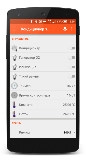
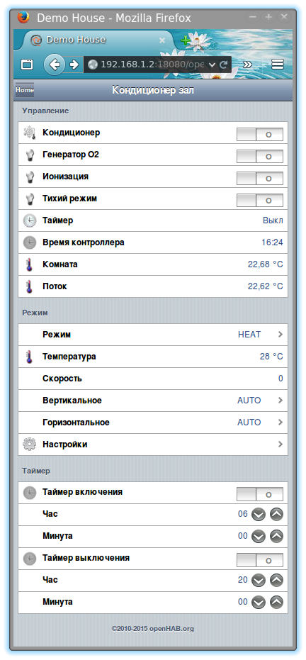
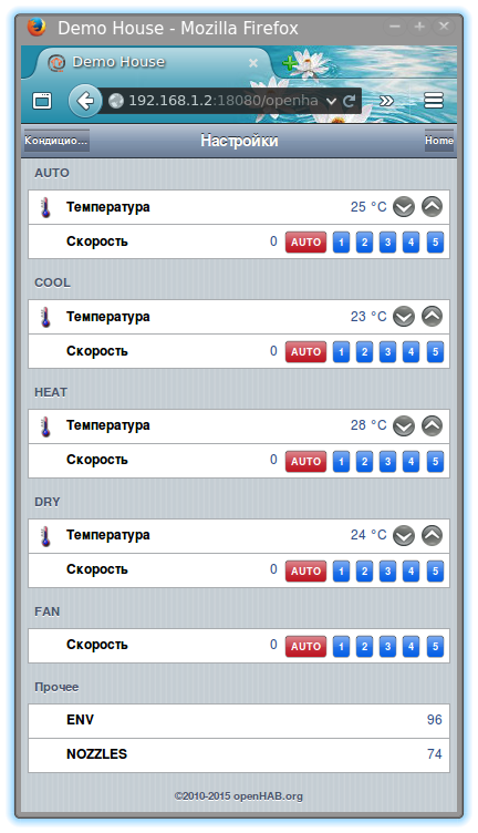
The result looks something like this through a browser:
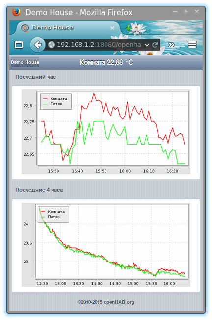
Conclusion
I am pleased with the result as an elephant. Air conditioning control is now available to me wherever there is mobile Internet or WiFI. Using a VPN client on a smartphone, OpenHAB on my home server becomes accessible to me both through a browser and through a mobile application.
The wireless solution made it possible to closely integrate the controller with air conditioning.
The presence of feedback gives confidence that the sent command was received by the air conditioner, and the temperature sensors clearly demonstrate this - after a few seconds you can observe a change in the temperature reading at the outlet of the air conditioner. Well, after a few minutes - and the ambient temperature.
It was interesting to observe the profile of the air conditioner when approaching the given conditions.
Undoubtedly this will not be the only wireless controller that I plan to use.
There are plans to use the IR receiver of the air conditioner itself to read the commands of the native remote control to update the settings in the controller. Moreover, the IR receiver itself is already connected via an optocoupler to the controller.
Read to the end a special thank you!
References
- Arduino library ModbusRtu Modbus-Master-Slave-for-Arduino
- Arduino library ModbusRtuRF24 Modbus-over-RF24 Network-for-Arduino