My DIY watch option with NTP client
Since in previous publications it never came to the finished product, I propose my own version. Iron is not my specialization, so please do not judge strictly.
So, in order. When my love of watches and the exact time reached the terminal stage, it was decided to make the dream come true. The search began for affordable boards for development with Ethernet on board. Rapsberry with Linux seemed like a “gun on sparrows”, so I threw a question on the Netduino forum, because now I am sitting tight on C # and it was interesting to run bytecode on the microcontroller. But alas, the only moderator of the forum, apparently, went on vacation, and it took him several weeks to approve and publish my first message. Not good, not good ... An Arch Pro board and other missing body kit were ordered on aliexpress. Then it was the most affordable solution. The NXP LPC1768 microcontroller (core Cortex-M3), plus LPC11U35 (Cortex-M0) is installed on the board itself to facilitate communication with their software. The manufacturer itself provides an online IDE, compilation is also on their server, the firmware is downloaded and downloaded onto the board as a file on a USB flash drive, there is no debugger, so I started developing the project in Keil uVision, a trial version, of course. Only micro-USB cable is required for flashing and debugging the microcontroller.
The DS3231 IC was chosen as a real-time clock, which came to me in the form of a ready-made module that communicates via I2C: For
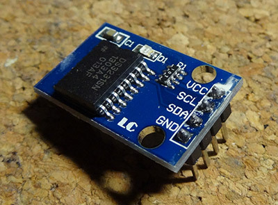
some reason, the mysterious module only worked when the logical analyzer was connected and powered up (I use Logic-U ISL from the guys from Kharkov):

By datasheet there should be 10K resistors between the signal lines and V +, the module's ringing showed megaoms. What kind of dummy instead of a resistor assembly and an LED that never lights up, I did not understand. The soldered resistors the module revived, but the collective farm threshold crossed a certain line, so a board was developed like the Arduino “shield”:

Diagram:
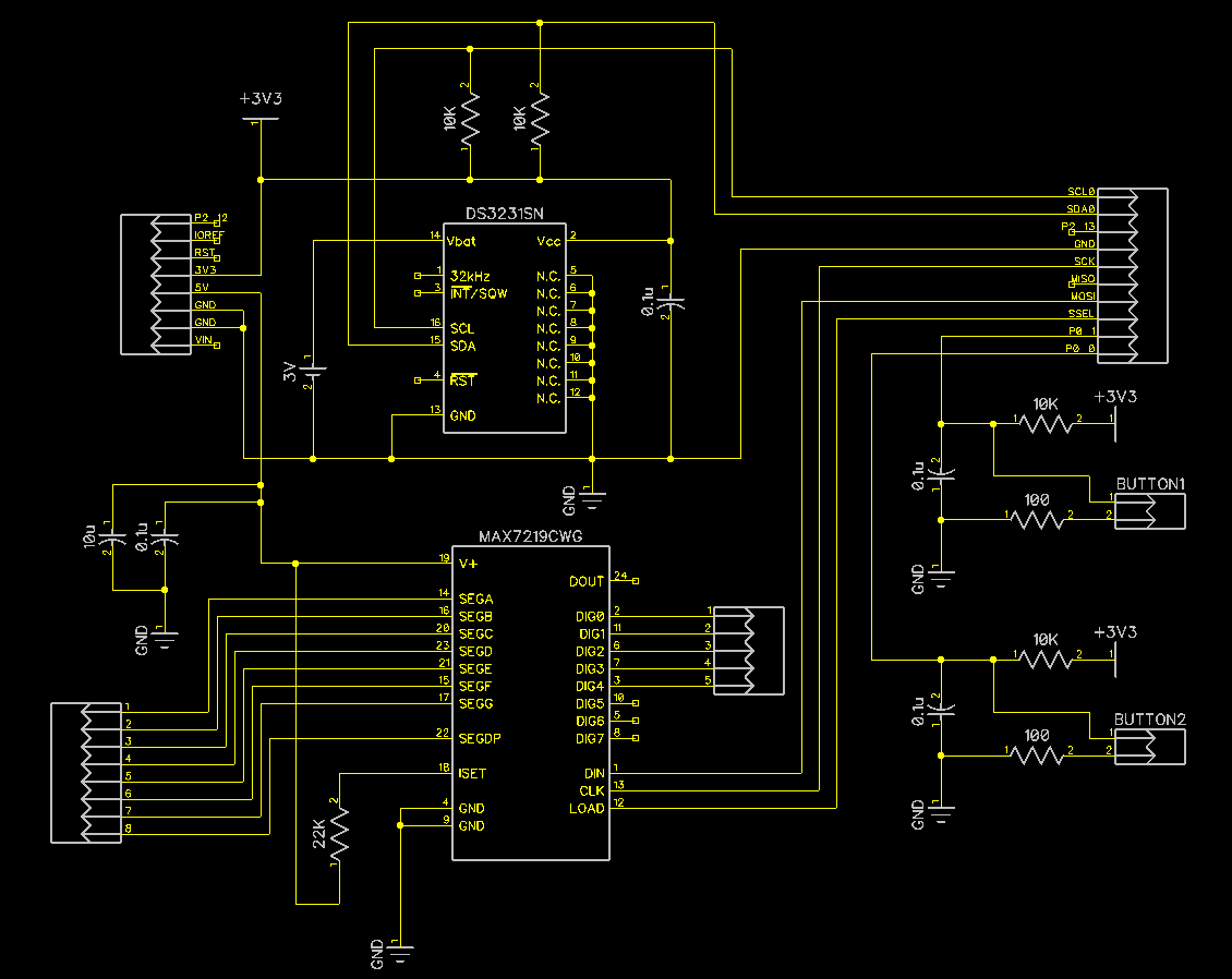
A segment display was taken as an indicator - this size (0.8 ″ in height) was only with white LEDs, from all the documentation on it, the Chinese provided only a jeep with pinout, some unreadable characters had to be guessed by the exclusion method. The controller for it was taken by the well-known MAX7219, communicating by SPI.
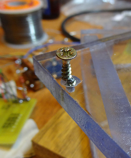
Case ... On New Year's holidays, of course, there is no 3D printer or laser cutting at hand. I myself sawed a 8 mm plexiglass lying around.
The moment of hopelessness in the final stage:
Final product view:

The clock receives an IP address via DHCP (a router distributes them to me). The NTP server is randomly selected. Time is requested every 25 hours (my provider disconnects from the Internet at the same time in the evening, so I would not want to get into this period of time). Due to the constantly changing legislation with time zones, I decided not to implement the transition to summer and winter time, two buttons simply reduce or increase the offset from UTC by an hour. The offset is recorded in the EEPROM of the microcontroller. The clock is additionally backed up by a 3V lithium battery, so power and internet outages are not a problem. Four color LEDs on the board are used to indicate problems with the Internet, hardware or errors in runtime.
The source code for the firmware on the github:
https://github.com/sapozhnikov/eclock
So, in order. When my love of watches and the exact time reached the terminal stage, it was decided to make the dream come true. The search began for affordable boards for development with Ethernet on board. Rapsberry with Linux seemed like a “gun on sparrows”, so I threw a question on the Netduino forum, because now I am sitting tight on C # and it was interesting to run bytecode on the microcontroller. But alas, the only moderator of the forum, apparently, went on vacation, and it took him several weeks to approve and publish my first message. Not good, not good ... An Arch Pro board and other missing body kit were ordered on aliexpress. Then it was the most affordable solution. The NXP LPC1768 microcontroller (core Cortex-M3), plus LPC11U35 (Cortex-M0) is installed on the board itself to facilitate communication with their software. The manufacturer itself provides an online IDE, compilation is also on their server, the firmware is downloaded and downloaded onto the board as a file on a USB flash drive, there is no debugger, so I started developing the project in Keil uVision, a trial version, of course. Only micro-USB cable is required for flashing and debugging the microcontroller.
The DS3231 IC was chosen as a real-time clock, which came to me in the form of a ready-made module that communicates via I2C: For
some reason, the mysterious module only worked when the logical analyzer was connected and powered up (I use Logic-U ISL from the guys from Kharkov):
By datasheet there should be 10K resistors between the signal lines and V +, the module's ringing showed megaoms. What kind of dummy instead of a resistor assembly and an LED that never lights up, I did not understand. The soldered resistors the module revived, but the collective farm threshold crossed a certain line, so a board was developed like the Arduino “shield”:
Diagram:
A segment display was taken as an indicator - this size (0.8 ″ in height) was only with white LEDs, from all the documentation on it, the Chinese provided only a jeep with pinout, some unreadable characters had to be guessed by the exclusion method. The controller for it was taken by the well-known MAX7219, communicating by SPI.
Case ... On New Year's holidays, of course, there is no 3D printer or laser cutting at hand. I myself sawed a 8 mm plexiglass lying around.
The moment of hopelessness in the final stage:
Final product view:
The clock receives an IP address via DHCP (a router distributes them to me). The NTP server is randomly selected. Time is requested every 25 hours (my provider disconnects from the Internet at the same time in the evening, so I would not want to get into this period of time). Due to the constantly changing legislation with time zones, I decided not to implement the transition to summer and winter time, two buttons simply reduce or increase the offset from UTC by an hour. The offset is recorded in the EEPROM of the microcontroller. The clock is additionally backed up by a 3V lithium battery, so power and internet outages are not a problem. Four color LEDs on the board are used to indicate problems with the Internet, hardware or errors in runtime.
The source code for the firmware on the github:
https://github.com/sapozhnikov/eclock