Making a metal detector on ATtiny24A
I played with Arduino-like boards for a long time, but all the time I wanted to “less, cheaper and closer to the hardware!”, And here is the first experience of programming pure ATtiny. The article will not be some particularly effective metal detector circuit. This is just a demonstration of what the microcontroller is capable of for 47 cents + the kettle’s path in this, as it turned out, is not at all complicated matter of moving from Arduino to a lower level.
After a short analysis, the choice fell on the ATtiny24A-SSU (14-pin SOIC package). Why? The reason is simple: price + AVR core. Yes, I know that an even more powerful STM8S103F3P6 costs less ( 39.5 cents apiece against 47 for ATtiny ), but having some experience with AVR in Arduino I wanted AVR for the first experiments.
From the available AVRs, we select ATtiny as the cheapest, and then I want the DIP package as easier to solder. But the chips in the DIP package turned out to be much more expensive ( 54 cents for the 8-foot ATtiny13A , and the 14-foot ATtiny23A in the DIP package is 95 cents ). I don't like the idea of using the ATtiny13A because of its octopus. 6 legs will be occupied by the programmer and only 2 remain free, which is not enough.
It was decided to buy ATtiny24A-SSU for 47 cents and another adapter for 30 cents . In total, we get 77 cents per device versus 95 for a DIP package and, as a bonus, in simple devices use an adapter as a board with soldering wires directly to it, which would be impossible with a DIP package.
The programmer is selected by the same principle (the cheapest): USBasp for $ 1.86 .
I must say right away that I never soldered a SOIC case before, so there was some fear that it would not work ... It turned out to be not difficult, not easy ... in general, I had to make some efforts, but in the end it turned out! It seemed advisable to warm up not by one conclusion, but immediately by groups - this is faster and easier.

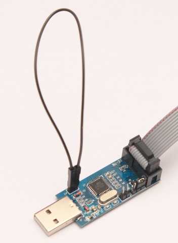
ATtiny24A by default is clocked from the internal generator and operates at a frequency of 1 MHz. Well, let it work, it suits me perfectly. But in order for USBasp to work with him at such a frequency, he had to solder an additional jumper (postings on the photo): There was a place on the board, but the Chinese did not bother to solder the jumper ... they had to do it for them. In terms of the development environment, the choice fell on Atmel Studio, but it does not support our USBasp ... but it doesn’t matter! Even when choosing a programmer, it was planned to upgrade it to AVR-Doper, which is compatible with the STK500, which means it is supported by our Atmel Studio. In general, I flashed it many times with different firmware, but Atmel Studio didn’t want to see it ... sadness ... in the end I despaired, flashed it back to USBasp and did it by tool
. After that, I managed to flash my ATtiny, blink an LED and enjoy how little flash memory it took compared to Arduino.
Even when I dabbled with Arduino, I made a metal detector working on the principle of resonance disruption. The sensitivity is terrible, but the principle of operation is very simple and easily implemented on any MK. A rectangular signal is applied to a parallel oscillating circuit through a resistor at the resonant frequency of this circuit. When a metal object enters the magnetic field of the coil, the quality factor of the circuit drops, the signal amplitude measured by the ADC drops, the device pleases us visually and acoustically.
The detector has 2 modes:
1. Search for the resonance of the circuit. At the same time, it sends rectangular signals of different frequencies to the circuit and remembers the frequency at which the amplitude of the oscillations will be the largest (we also remember this largest amplitude).
2. The operating mode. We send a signal with a resonant frequency to the circuit and compare the amplitude with the maximum that was in the first mode.
Difficult? - Not!
Should you take up a lot of memory? - Not!
Do we have a lot of memory (2 KB flash + 128 bytes of RAM)? - Also no!
Does it fit in? Let's try - we will find out!
In the end, fit.
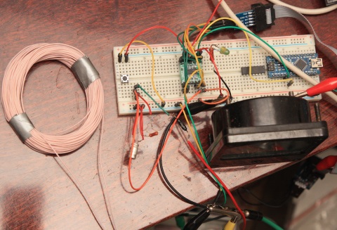
And not only that fit, so it takes only 1044 bytes in flash from the available 2048! And this despite the fact that in addition to the main function, it also sends debugging information (MySerial)! I’ll explain a little bit why here (from left to right):
Scheme:

The sensitivity turned out to be too low to be used in practice. A weight of 0.5 kg can be felt with about 7 centimeters, and a coin like that only if thrown inside the coil. But, in general, the device works:
The recording shows how, when a metal object is placed in the coil, the ADC readings fall (on the screen) and the MK increases the current through the indicator.
The task of "playing with ATtiny" has been completed. Everything works, everything is fine. The rake on the road was even less than expected. But because of the fact indicated at the beginning (that even the more powerful STM8S103F3P6 is cheaper), I see only two reasons to do something on the AVR: simplicity and good documentation. Well, maybe even twice as much as the maximum allowable output current in some cases can be an argument.
Iron selection
After a short analysis, the choice fell on the ATtiny24A-SSU (14-pin SOIC package). Why? The reason is simple: price + AVR core. Yes, I know that an even more powerful STM8S103F3P6 costs less ( 39.5 cents apiece against 47 for ATtiny ), but having some experience with AVR in Arduino I wanted AVR for the first experiments.
From the available AVRs, we select ATtiny as the cheapest, and then I want the DIP package as easier to solder. But the chips in the DIP package turned out to be much more expensive ( 54 cents for the 8-foot ATtiny13A , and the 14-foot ATtiny23A in the DIP package is 95 cents ). I don't like the idea of using the ATtiny13A because of its octopus. 6 legs will be occupied by the programmer and only 2 remain free, which is not enough.
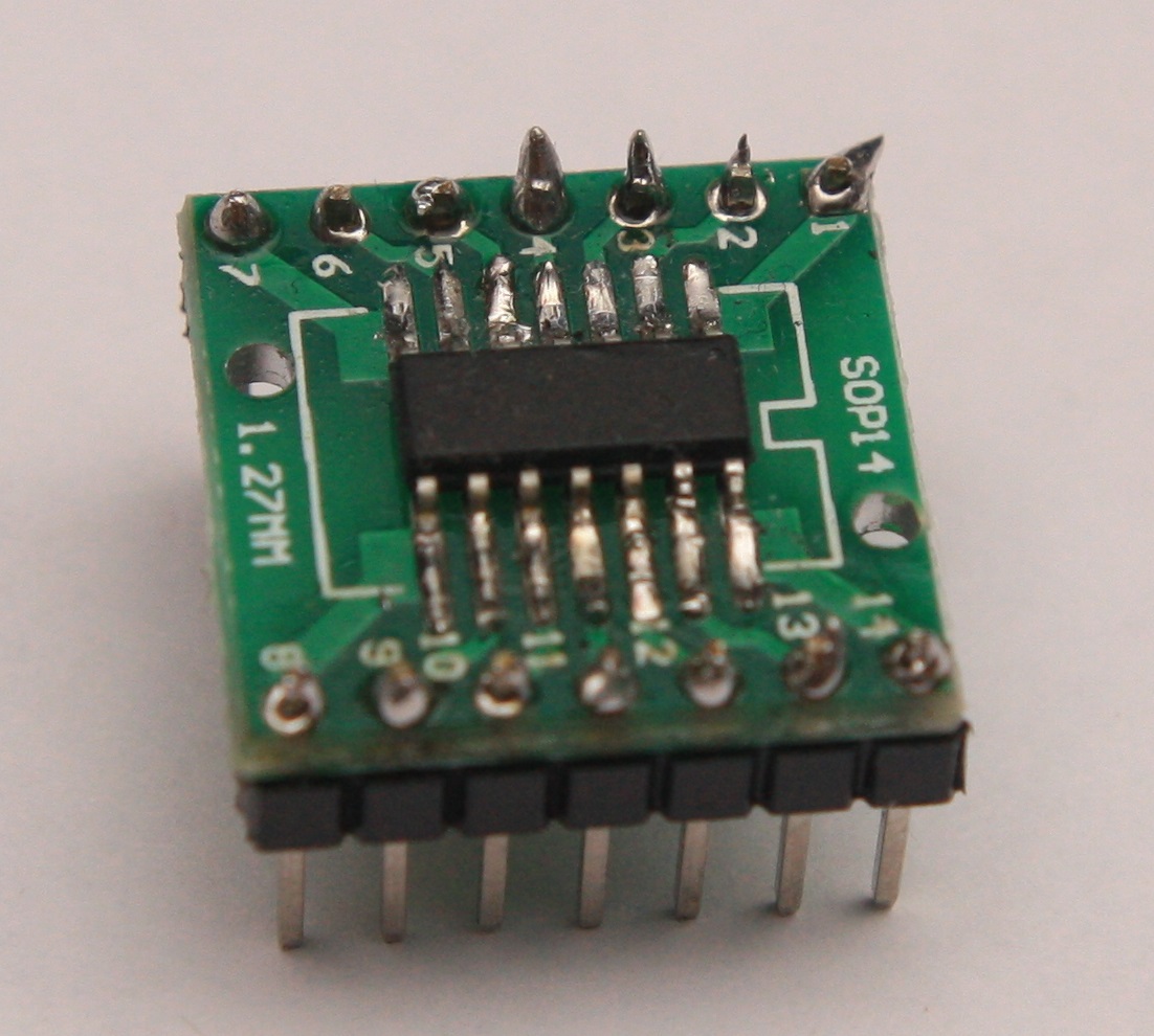
It was decided to buy ATtiny24A-SSU for 47 cents and another adapter for 30 cents . In total, we get 77 cents per device versus 95 for a DIP package and, as a bonus, in simple devices use an adapter as a board with soldering wires directly to it, which would be impossible with a DIP package.
The programmer is selected by the same principle (the cheapest): USBasp for $ 1.86 .
Arrived!
I must say right away that I never soldered a SOIC case before, so there was some fear that it would not work ... It turned out to be not difficult, not easy ... in general, I had to make some efforts, but in the end it turned out! It seemed advisable to warm up not by one conclusion, but immediately by groups - this is faster and easier.
How to program?
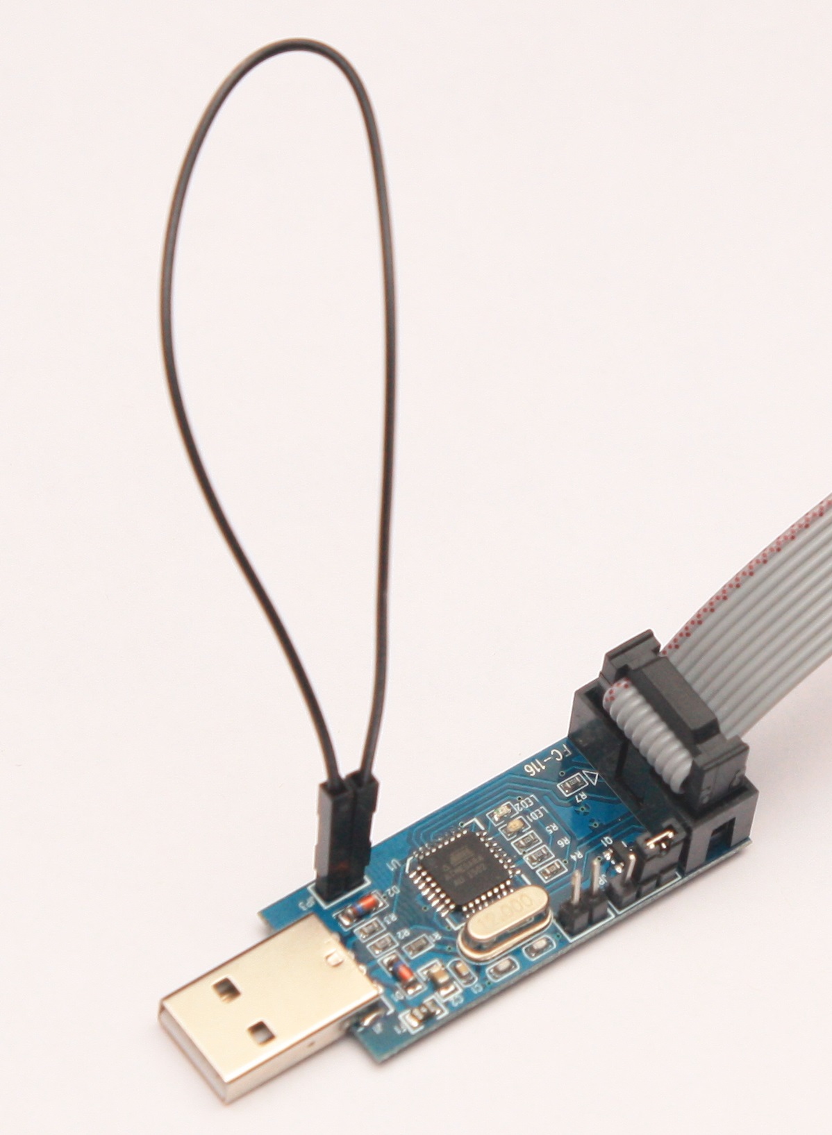
ATtiny24A by default is clocked from the internal generator and operates at a frequency of 1 MHz. Well, let it work, it suits me perfectly. But in order for USBasp to work with him at such a frequency, he had to solder an additional jumper (postings on the photo): There was a place on the board, but the Chinese did not bother to solder the jumper ... they had to do it for them. In terms of the development environment, the choice fell on Atmel Studio, but it does not support our USBasp ... but it doesn’t matter! Even when choosing a programmer, it was planned to upgrade it to AVR-Doper, which is compatible with the STK500, which means it is supported by our Atmel Studio. In general, I flashed it many times with different firmware, but Atmel Studio didn’t want to see it ... sadness ... in the end I despaired, flashed it back to USBasp and did it by tool
. After that, I managed to flash my ATtiny, blink an LED and enjoy how little flash memory it took compared to Arduino.
Metal detector
Even when I dabbled with Arduino, I made a metal detector working on the principle of resonance disruption. The sensitivity is terrible, but the principle of operation is very simple and easily implemented on any MK. A rectangular signal is applied to a parallel oscillating circuit through a resistor at the resonant frequency of this circuit. When a metal object enters the magnetic field of the coil, the quality factor of the circuit drops, the signal amplitude measured by the ADC drops, the device pleases us visually and acoustically.
The detector has 2 modes:
1. Search for the resonance of the circuit. At the same time, it sends rectangular signals of different frequencies to the circuit and remembers the frequency at which the amplitude of the oscillations will be the largest (we also remember this largest amplitude).
2. The operating mode. We send a signal with a resonant frequency to the circuit and compare the amplitude with the maximum that was in the first mode.
Difficult? - Not!
Should you take up a lot of memory? - Not!
Do we have a lot of memory (2 KB flash + 128 bytes of RAM)? - Also no!
Does it fit in? Let's try - we will find out!
In the end, fit.
The main firmware code
#include#include #include "mySerial.cpp" MySerial ms (& PORTB, & PINB, & DDRB, 0, & PORTB, & PINB, & DDRB, 1); volatile uint16_t maxAdc = 0; // maximum ADC reading (in resonance at maximum quality factor) volatile uint8_t dispMode = 0; // 0 - resonance search, 1 - operating mode volatile uint8_t flags0 = 0; // [0] - need setRes volatile uint16_t adcSource = 0; // volatile bool needADC = false; #define ADC_SOURCE_ARRAY_SIZE_POWER 5 #define ADC_SOURCE_ARRAY_SIZE (1 << ADC_SOURCE_ARRAY_SIZE_POWER) uint16_t adcSourceArray [ADC_SOURCE_ARRAY_SIZE]; uint8_t adcSourceArrayLastWrited = 0; void showVal (void); ISR (ADC_vect) { // adcSourceArrayLastWrited ++; if (++ adcSourceArrayLastWrited> = ADC_SOURCE_ARRAY_SIZE) adcSourceArrayLastWrited = 0; adcSourceArray [adcSourceArrayLastWrited] = ADCL | (ADCH << 8); uint16_t adcSourceTmp = 0; for (uint8_t i = 0; i <ADC_SOURCE_ARRAY_SIZE; i ++) adcSourceTmp + = adcSourceArray [adcSourceArrayLastWrited]; adcSource = (adcSourceTmp >> ADC_SOURCE_ARRAY_SIZE_POWER); // adcSource = ADCL | (ADCH << 8); // needADC = false; } volatile uint8_t pinaChanged = 0; volatile uint8_t tim0_ovf_counter = 0; // uint32_t ticks = 0; volatile uint16_t ticks10ms = 0; // volatile uint16_t ticks = 0; ISR (TIM0_OVF_vect) { // ticks ++; // if (255 == tim0_ovf_counter ++) {// ticks every 65.5 ms if (39 == (tim0_ovf_counter ++)) {// ticks every 10 ms tim0_ovf_counter = 0; ticks10ms ++; if (pinaChanged> 0) pinaChanged--; } } uint16_t dist16 (uint16_t lo, uint16_t hi) { return (lo <= hi)? (hi - lo): (0xFFFF - lo + hi); } / * void delayTicks (uint16_t val) { uint16_t tim0_ovf_counter0 = tim0_ovf_counter; while (dist16 (tim0_ovf_counter0, tim0_ovf_counter) <val) showVal (); } * / void delay10ms (uint16_t val) { uint16_t ticks10ms0 = ticks10ms; while (dist16 (ticks10ms0, ticks10ms) <val) showVal (); } void showVal (void) { ms.sendByte (adcSource >> 2); switch (dispMode) { case 0: OCR0A = adcSource >> 2; break; case 1: uint16_t maxAdcPlus = maxAdc + 2; uint16_t dispVal = (maxAdcPlus> adcSource)? ((maxAdcPlus - adcSource)): 0; dispVal << = 4; if (dispVal> 255) dispVal = 255; OCR0A = dispVal; break; } } void setRes (void) { dispMode = 0; uint16_t maxOCR = 0; maxAdc = 0; for (uint16_t curOCR = 35; curOCR <50; curOCR ++) { OCR1A = curOCR; OCR1B = (curOCR >> 1); // uint32_t ticks0 = ticks; // uint16_t ticks0 = ticks; // while (dist16 (ticks0, ticks) <20) // showVal (); delay10ms (30); if (adcSource> maxAdc) { maxAdc = adcSource; maxOCR = curOCR; } } OCR1A = maxOCR; OCR1B = (maxOCR >> 1); dispMode = 1; } ISR (PCINT0_vect) { if (pinaChanged> 0) return pinaChanged = 5; if (0 == (PINA & (1 << 7))) flags0 | = 1; } int main (void) { // init PWM: DDRB | = 4; // OC0A as output // TIMSK0 | = 7; // enable TIM0_OVF_vect, TIM0_COMPA_vect, TIM0_COMPB_vect TIMSK0 | = 1; // enable TIM0_OVF_vect TCCR0B | = 1; // no prescaling. OVF every 256 μs (3.91 kHz) // TCCR0B | = 2; // clk / 8 // TCCR0B | = 3; // clk / 64 // TCCR0B | = 5; // clk / 1024. OVF every 262 ms (3.815 Hz) TCCR0A | = (3 | (1 << 7)); // WGM0 [2: 0] = 3 - fawt PWM mode. bit7 - jerk your foot // OCR0A = 150; // OCR0B = 100; //: init PWM // init ADC: // ADMUX | = (1 << 7); // internal 1.1V reference. Comment this to use VCC as reference // ADMUX | = (1 << 3) | 1; // MUX [5: 0] = 001001. Res = ADC0 - ADC1. Gain = 20 ADMUX | = (1 << 3); // MUX [5: 0] = 001000. Res = ADC0 - ADC1. Gain = 1 ADCSRA | = ((1 << 7) // enable ADC | (1 << 5) // ADC Auto Trigger Enable. Constantly working | (1 << 6) // start the 1st conversion | (1 << 3) // ADC interrupt enable | (1 << 2)); // prescaller = 16 (need 50-200 kHz) //: init ADC // init 16-bit timer: // pin7 = MOSI = PA6 = OC1A // DDRA | = (1 << 6); // OC1A as output DDRA | = (1 << 5); // OC1B as output // TCCR1A | = (1 << 6); // Toggle OC1A / OC1B on Compare Match TCCR1A | = (1 << 5) // Clear OC1B on Compare Match, set OC1B at BOTTOM (non-inverting mode) | (3); // set WGM10 and WGM11 // WGM1 [3: 0] = 1111 - Fast PWM, TOP = OCR1A. // TCCR1A | = (1 << 6) | (1 << 7) // Set OC1A on Compare Match (Set output to high level). // | (1 << 5); // Clear OC1B on Compare Match (Set output to low level) TCCR1B | = 1 // no prescalling | (1 << 3) | (1 << 4); // set WGM12 and WGM13 // TIMSK1 | = (1 << 2) | (1 << 1) | 1; // enable all interrupts OCR1B = 21; OCR1A = 42; // for (;;) {;}; //: init 16-bit timer // init button: PORTA | = (1 << 7); // turn on the pull-up resistor on the 6th leg. PA7 = PCINT7 GIMSK | = (1 << 4); // Pin Change Interrupt Enable 0 PCMSK0 | = (1 << 7); // enable PCINT7 interrupt //: init button sei (); flags0 = 1; // this saves 22 bytes compared to assignment on declaration! while (1) { showVal (); //ms.sendByte(0x99); if (0! = (1 & flags0)) { setRes (); flags0 & = ~ 1; } } }
And mySerial.cpp
#include#include class MySerial { public: volatile uint8_t * dataPort; volatile uint8_t * dataPin; volatile uint8_t * dataDDR; volatile uint8_t * clockPort; volatile uint8_t * clockPin; volatile uint8_t * clockDDR; uint8_t dataPinMask, clockPinMask; uint8_t rBit, lastState, // (dataPin << 1) | clockpin inData; // MySerial ms (& PORTD, & PIND, & DDRD, 2, & PORTD, & PIND, & DDRD, 3); MySerial ( volatile uint8_t * _dataPort, volatile uint8_t * _dataPin, volatile uint8_t * _dataDDR, uint8_t _dataPinN, volatile uint8_t * _clockPort, volatile uint8_t * _clockPin, volatile uint8_t * _clockDDR, uint8_t _clockPinN ) { rBit = 255; lastState = 3; inData = 0; dataPort = _dataPort; dataPin = _dataPin; dataDDR = _dataDDR; dataPinMask = (1 << _dataPinN); clockPort = _clockPort; clockPin = _clockPin; clockDDR = _clockDDR; clockPinMask = (1 << _clockPinN); } void dataZero () { * dataPort & = ~ dataPinMask; // digitalWrite (pinData, 0); * dataDDR | = dataPinMask; // pinMode (pinData, OUTPUT); } void dataRelease () { * dataDDR & = ~ dataPinMask; // pinMode (pinData, INPUT); * dataPort | = dataPinMask; // digitalWrite (pinData, 1); } void clockZero () { * clockPort & = ~ clockPinMask; // digitalWrite (pinClock, 0); * clockDDR | = clockPinMask; // pinMode (pinClock, OUTPUT); } void clockRelease () { * clockDDR & = ~ clockPinMask; // pinMode (pinClock, INPUT); * clockPort | = clockPinMask; // digitalWrite (pinClock, 1); } void pause () { // delay (v * 1); // unsigned long time = micros (); // while (v--> 0) for (uint16_t i = 0; i <250; i ++) __asm__ __volatile __ ( "nop" ); // time = micros () - time; // LOG ("Paused"); LOG (time); LOGLN ("us"); } void sendByte (uint8_t data) { // LOG ("Sending byte:"); LOGLN (data); // negative edge of data with clock = 1: dataRelease (); clockRelease (); pause (); dataZero (); pause (); // LOGLN ("Going to loop ..."); for (uint8_t i = 0; i <8; i ++) { clockZero (); pause (); if (0 == (data & (1 << 7))) dataZero (); else dataRelease (); // LOG ("Sending bit"); LOGLN ((data & (1 << 7))); pause (); clockRelease (); pause (); data = data << 1; } // positive edge of data with clock = 1: dataZero (); pause (); dataRelease (); pause (); } void tick () { // uint8_t curState = (digitalRead (pinData) << 1) | digitalRead (pinClock); dataRelease (); clockRelease (); uint8_t curState = 0; if (0! = (* dataPin & dataPinMask)) curState | = 2; if (0! = (* clockPin & clockPinMask)) curState | = 1; // LOGLN (curState); if ((3 == lastState) && (1 == curState)) // transfer started rBit = 7; if (255! = rBit) if ((0 == (lastState & 1)) && (1 == (curState & 1))) {// a positive edge came clock // LOG ("Getted bit"); LOGLN ((curState >> 1)); if (0 == (curState >> 1)) inData & = ~ (1 << rBit); else inData | = (1 << rBit); rBit--; } if ((1 == lastState) && (3 == curState)) {// transfer ended // LOG ("Recieved byte:"); LOGLN (inData); rBit = 255; // delay (5000); } lastState = curState; } };
And not only that fit, so it takes only 1044 bytes in flash from the available 2048! And this despite the fact that in addition to the main function, it also sends debugging information (MySerial)! I’ll explain a little bit why here (from left to right):

- A coil of wire is a sensitive coil of a metal detector;
- The button on the left of the breadboard - calls the resonance detection function;
- Diode + resistor + capacitor is an amplitude detector;
- Green shawl - adapter with ATtiny24A on it;
- LED with a resistor and a large black box (this is an ancient microammeter) - PWM indication;
- Arduino Nano connected by two wires - a receiver for debugging information.
Scheme:
- L1, C1 - oscillatory circuit;
- D1, C2, R2 - amplitude detector.
The sensitivity turned out to be too low to be used in practice. A weight of 0.5 kg can be felt with about 7 centimeters, and a coin like that only if thrown inside the coil. But, in general, the device works:
The recording shows how, when a metal object is placed in the coil, the ADC readings fall (on the screen) and the MK increases the current through the indicator.
What's next?
The task of "playing with ATtiny" has been completed. Everything works, everything is fine. The rake on the road was even less than expected. But because of the fact indicated at the beginning (that even the more powerful STM8S103F3P6 is cheaper), I see only two reasons to do something on the AVR: simplicity and good documentation. Well, maybe even twice as much as the maximum allowable output current in some cases can be an argument.









