3D Prism Uni 3D Printer Assembly Instructions (Part 2-Electrician)
- Tutorial
I would like to clarify the previous post on the assembly of the mechanics of Prism uni. Due to the great popularity and demand, we decided to make open access to the drawings of the first version of the model so that everyone can make and assemble a printer on their own, and we are ready to share with the assembly drawings and practical experience gained) We really hope that the previous and this article will help beginners in 3D printing technology in the assembly of Prism Uni or another similar printer. Now let's look at the process of assembling the electrical part of the printer.
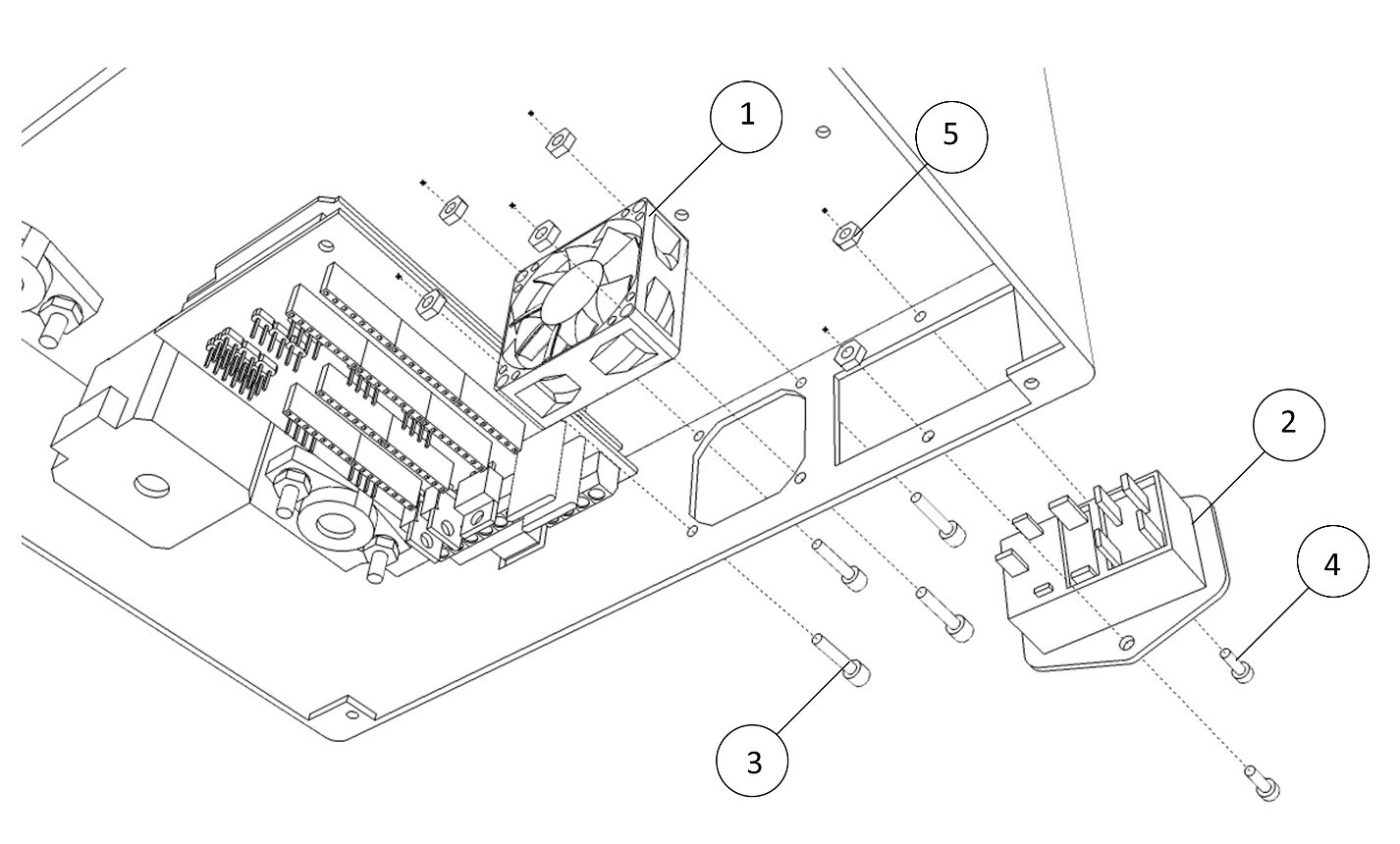
1-wiring. Installing the Ramps Board 1.4.
Install the network input unit and fan as shown in fig. below.
2-wiring. Install the power supply.
Install the power supply as shown in fig. below.

3-wiring.
Electrical installation of turbine wires.
Trim wires at connector.
Install the turbine wires according to fig.
Insulate the solder points with a heat shrink tube.
Press in the tips.
Length of stackable wires 600mm

4-wiring.
El.installation of wires cooler hotend.
Trim wires at connector.
Install the cooler wires - build-up the wires, according to fig.
Insulate the solder points with a heat shrink tube.
Press in the tips.
The length of the stacked wires is 600mm.

5-wiring.
Electrical installation of limit switch X.
Install limit switch according to fig.
Insulate the solder points with a heat shrink tube.
Install a 2-pin connector.
The length of the stacked wires is 450mm.

6-wiring.
Electrical installation of limit switch Y. Install limit switch
according to fig.
Insulate the solder points with a heat shrink tube.
Install a 2-pin connector.
The length of the stacked wires is 650mm.
7-wiring.
Electrical installation of limit switch Z. Install limit switch
according to fig.
Insulate the solder points with a heat shrink tube.
Install a 2-pin connector.
The length of the stacked wires is 650mm.
8-wiring.
El.installation of the network input unit.
Install the network input unit according to fig.
Solder the black wire to the terminal (L = 80mm)
solder the 1st red wire to the terminal N (L = 80mm)
solder the 2nd red wire to the N switch (L = 80mm) - see the figure
Solder the jumper from terminal L to the switch ( L-50mm) - see figure.
Insulate soldering points with heat-shrink tubing.
Press the return ends of the wires under the lugs.
After soldering, check the wiring for correct wiring.

9-wiring.
Electrical installation of the DC connector.
Install the DC connector according to fig.
Black wire (L = 100mm)
Red wire (L = 100mm)
Pay attention to the location of the wires relative to the key.
Insulate the soldering points with the heat shrink tube.
Press the return ends of the wires under the lugs.
After soldering, check the wiring for correct wiring.

10-wiring.
Mounting the contacts of the board in Ramps1.4 1.
Solder the Ramps 1.4, 2-pin, into the board Ramps 1.4, to connect a 2-pin connector (connecting the cooler blowing hotend) according to Fig.
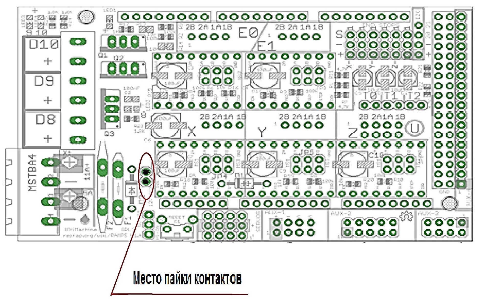
The pin pins should be routed to the side of the placement of the electronic board (opposite to the side of the connection to the Arduino).
Check the quality of soldering with a continuity.

2. Bend the power connector as shown.

11th Wiring.
Laying wires in the cable channel.
1. Fasten the cable channel to the housing.
2. Lay the wires from the heater, thermistor, fans and motor in the
cable channel, according to fig.

12-wiring.
Electrical installation of the X axis.
1. Route the wires from the limit switch X into the hole on the side of the housing, see fig.

2. Connect the connector with wires to the X-axis engine (see figure).

13-wiring.
Internal cable routing.
1. Route the wire from the limit switch Z to all other wires according to fig.

2. Lay all wires drawn inside the case down through the hole in the corner
of the Case , in the following sequence:
2.1. In the 1st stage, wires from a stepper motor and an extruder are passed.
2.2. In the second turn, the remaining wires are passed - from the limit switches,
extruder, thermistor, turbines and cooler.
Pay attention to the length of the wires along the X axis - the length of the wires should allow the
extruder to move freely to the most extreme points.
14-wiring.
Laying the Y-axis harness.
1. Collect and run the wires from the heating table and the thermistor into a separate braid. (see fig.)
2. Collect and run wires from the Y-axis motor and the Y-axis limit switch into a separate braid. (see. Fig.)
3. Combine the wires and run into a common braid. (see. Fig.)
4. Insert a braid with wires into the hole in the lower frame. (see fig.)

Pay attention to the length of the wires from the heating table and the thermistor - the length of the wires should allow the
table to move freely to the most extreme points.
15-wiring.
1. Make the connections according to the diagram.

16-wiring.
Installing drivers on Ramps1.4
Install the A4988 drivers on the Ramps 1.4 board, as shown in the figure.

2. Glue radiators according to the picture with hot-melt adhesive.

17-wiring.
Final operations.
1. Pull the excess wires into the lower frame and secure with a cable tie.
2. Collect all the wires drawn inside the housing into a bundle and tighten to the housing with ties.
3. Tie the wires running on the outside (Y axis) to the frame with cable ties (13th wiring, see fig.)
4. Install the bottom cover, tighten the screws.
Now you can proceed to testing and calibrating the printer.
1-wiring. Installing the Ramps Board 1.4.
Install the network input unit and fan as shown in fig. below.
2-wiring. Install the power supply.
Install the power supply as shown in fig. below.
3-wiring.
Electrical installation of turbine wires.
Trim wires at connector.
Install the turbine wires according to fig.
Insulate the solder points with a heat shrink tube.
Press in the tips.
Length of stackable wires 600mm
4-wiring.
El.installation of wires cooler hotend.
Trim wires at connector.
Install the cooler wires - build-up the wires, according to fig.
Insulate the solder points with a heat shrink tube.
Press in the tips.
The length of the stacked wires is 600mm.
5-wiring.
Electrical installation of limit switch X.
Install limit switch according to fig.
Insulate the solder points with a heat shrink tube.
Install a 2-pin connector.
The length of the stacked wires is 450mm.
6-wiring.
Electrical installation of limit switch Y. Install limit switch
according to fig.
Insulate the solder points with a heat shrink tube.
Install a 2-pin connector.
The length of the stacked wires is 650mm.
7-wiring.
Electrical installation of limit switch Z. Install limit switch
according to fig.
Insulate the solder points with a heat shrink tube.
Install a 2-pin connector.
The length of the stacked wires is 650mm.
8-wiring.
El.installation of the network input unit.
Install the network input unit according to fig.
Solder the black wire to the terminal (L = 80mm)
solder the 1st red wire to the terminal N (L = 80mm)
solder the 2nd red wire to the N switch (L = 80mm) - see the figure
Solder the jumper from terminal L to the switch ( L-50mm) - see figure.
Insulate soldering points with heat-shrink tubing.
Press the return ends of the wires under the lugs.
After soldering, check the wiring for correct wiring.
9-wiring.
Electrical installation of the DC connector.
Install the DC connector according to fig.
Black wire (L = 100mm)
Red wire (L = 100mm)
Pay attention to the location of the wires relative to the key.
Insulate the soldering points with the heat shrink tube.
Press the return ends of the wires under the lugs.
After soldering, check the wiring for correct wiring.
10-wiring.
Mounting the contacts of the board in Ramps1.4 1.
Solder the Ramps 1.4, 2-pin, into the board Ramps 1.4, to connect a 2-pin connector (connecting the cooler blowing hotend) according to Fig.
The pin pins should be routed to the side of the placement of the electronic board (opposite to the side of the connection to the Arduino).
Check the quality of soldering with a continuity.
2. Bend the power connector as shown.
11th Wiring.
Laying wires in the cable channel.
1. Fasten the cable channel to the housing.
2. Lay the wires from the heater, thermistor, fans and motor in the
cable channel, according to fig.
12-wiring.
Electrical installation of the X axis.
1. Route the wires from the limit switch X into the hole on the side of the housing, see fig.
2. Connect the connector with wires to the X-axis engine (see figure).
13-wiring.
Internal cable routing.
1. Route the wire from the limit switch Z to all other wires according to fig.
2. Lay all wires drawn inside the case down through the hole in the corner
of the Case , in the following sequence:
2.1. In the 1st stage, wires from a stepper motor and an extruder are passed.
2.2. In the second turn, the remaining wires are passed - from the limit switches,
extruder, thermistor, turbines and cooler.
Pay attention to the length of the wires along the X axis - the length of the wires should allow the
extruder to move freely to the most extreme points.
14-wiring.
Laying the Y-axis harness.
1. Collect and run the wires from the heating table and the thermistor into a separate braid. (see fig.)
2. Collect and run wires from the Y-axis motor and the Y-axis limit switch into a separate braid. (see. Fig.)
3. Combine the wires and run into a common braid. (see. Fig.)
4. Insert a braid with wires into the hole in the lower frame. (see fig.)
Pay attention to the length of the wires from the heating table and the thermistor - the length of the wires should allow the
table to move freely to the most extreme points.
15-wiring.
1. Make the connections according to the diagram.
16-wiring.
Installing drivers on Ramps1.4
Install the A4988 drivers on the Ramps 1.4 board, as shown in the figure.
2. Glue radiators according to the picture with hot-melt adhesive.
17-wiring.
Final operations.
1. Pull the excess wires into the lower frame and secure with a cable tie.
2. Collect all the wires drawn inside the housing into a bundle and tighten to the housing with ties.
3. Tie the wires running on the outside (Y axis) to the frame with cable ties (13th wiring, see fig.)
4. Install the bottom cover, tighten the screws.
Now you can proceed to testing and calibrating the printer.