Can the ionistor replace the battery?
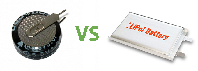
Today, battery technology has advanced significantly and has become more advanced compared to the past decade. But still, so far, the batteries remain consumables, because they have a small resource.
The idea of using a capacitor for storing and storing energy is not new, and the first experiments were conducted with electrolytic capacitors. The capacitance of electrolytic capacitors is significant - hundreds of thousands of microfarads, but still it is not enough to supply a long load, although not a large load, moreover, there is a significant leakage current due to design features.
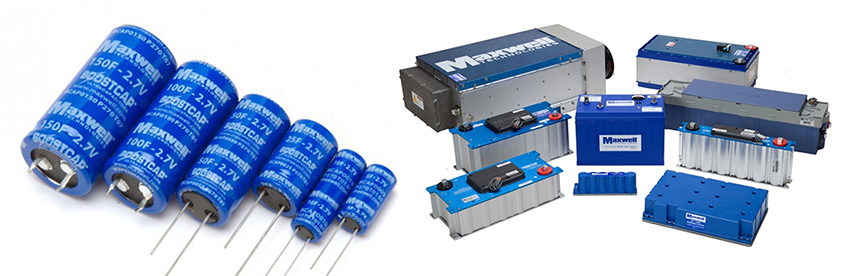
Modern technology does not stand still, and the ionistor was invented, this is a capacitor, has an extra-large capacity - from units of farads to tens of thousands of farads. Ionistors with a capacity of a unit of farad are used in portable electronics, to ensure uninterrupted power for low-current circuits, such as a microcontroller. And tens of thousands of farad ionistors are used in conjunction with batteries to power various electric motors. In this combination, the ionistor reduces the load on the batteries, which significantly increases their battery life and at the same time increases the starting current that the hybrid engine power system can give.
There was a need to power the temperature sensor, so as not to change the battery in it. The sensor is powered by a standard size AA battery and is turned on to send data to the weather station once every 40 seconds. At the time of sending, the sensor consumes an average of 6 mA for 2 seconds.
There was an idea to use a solar battery and an ionistor. Based on the detected consumption characteristics of the sensor, the following elements were taken:
1. 5 Volt solar battery and approximately 50 mA current (Soviet-made solar battery approximately 15 years old)
2. Ionistor: Panasonic 5.5 Volt and 1 farad capacity.
3. Ionistors 2 pcs: DMF 5.5 Volts and a total capacity of 1 farad.
4. Schottky diode with a direct voltage drop at a low current of 0.3 V.
A Schottky diode is needed to prevent the discharge of capacitance through a solar battery.
The ionistors are connected in parallel, and the total capacity is 2 farads.

Photo 1.
Experiment No. 1 - I connected a microcontroller with a monochrome LCD display and a total consumption current of 500 μA. Although the microcontroller with the display worked, but I noticed that the old solar cells were extremely inefficient, the charge current in the shade was not enough to charge the ionistors at all, the voltage on the 5-volt solar battery in the shade was less than 2 volts. (For some reasons, the microcontroller with the display is not shown in the photo).
Experiment 2
To increase the chance of success, I purchased on the radio market new solar cells with ratings of 2 V, current of 40 mA and 100 mA, Chinese-made flooded with optical resin. For comparison, these batteries in the shade already produced 1.8 volts, while not a large charge current, but still a charging ionistor is noticeably better.
Soldering the design already with a new battery, a Schottky diode and capacitors, I put it on the window sill so that the capacitor is charged.
Despite the fact that sunlight did not directly hit the battery, after 10 minutes the capacitor was charged up to 1.95 V. He took a temperature sensor, took out the battery from it and connected an ionistor with a solar battery to the contacts of the battery compartment.
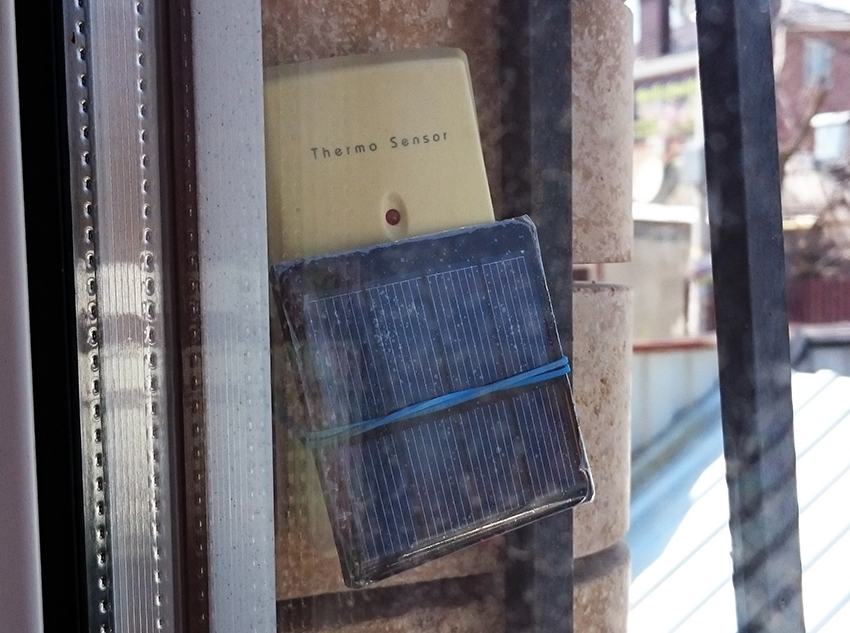
Photo 2.
The temperature sensor immediately started working and transmitted the room temperature to the weather station. After making sure that the sensor is working, he mounted a capacitor with a solar battery on it and hung it in place.
What happened next?
All daylight hours the sensor worked properly, but after dark, after an hour, the sensor stopped transmitting data. Obviously, the stored charge was not enough even for an hour of operation of the sensor, and then it became clear why ...
Experiment No. 3
I decided to slightly modify the design so that the ionistor (returned the assembly of 2 farad ionistors) was fully charged. I assembled a battery of three elements, it turned out 6 volts and a current of 40 mA (in full sunlight). This battery in the shade already gave up to 3.7 V instead of the previous 1.8 V (photo 1) and a charge current of up to 2 mA. Accordingly, the ionistor was charging up to 3.7 V and already had significantly more stored energy in comparison with Experiment No. 2.
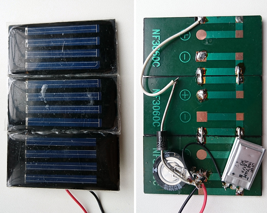
Photo 3.
Everything would be fine, but now we have up to 5.5 V output, and the sensor is powered by 1.5 V. A DC \ DC converter is required, which in turn introduces additional losses. The converter that I had in my possession consumed about 30 μA and gave 4.2 V at the output. So far I have not been able to find the required converter in order to power the temperature sensor already from the modernized design. (It will be necessary to select a converter and repeat the experiment).
About energy losses:
It was mentioned above that the ionistors have a self-discharge current, in this case it was 50 μA for assembly 2 farads, losses to the DC / DC converter of about 4% (declared efficiency 96%) and its idle speed 30 μA are also added here . If we do not take into account the conversion losses, we already have a consumption of about 80 μA.
It is necessary to take energy saving very carefully, because it has been experimentally established that an ionistor with a capacity of 2 farads charged up to 5.5 V and discharged up to 2.5 V has, so to say, a “battery” capacity of 1 mA. In other words, by consuming 1 mA from the ionistor for an hour, we discharge it from 5.5 V to 2.5 V.
About the charge speed in direct sunlight: The
current received from the solar battery is higher, the better the battery is illuminated by direct sunlight. Accordingly, the ionistor charge speed increases significantly.
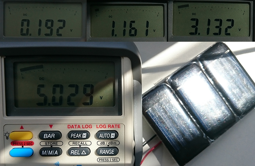
Photo 4.
From the readings of the multimeter it can be seen (0.192 V, initial readings), after 2 minutes the capacitor was charged to 1.161 V, after 5 minutes to 3.132 V and after another 10 minutes 5.029 V. Within 17 minutes, the ionistor was 90% charged. It should be noted that the lighting of the solar battery was uneven throughout the whole time and occurred through a double window glass and a protective film of the battery.
Technical report on Experiment No. 3
Technical characteristics of the layout:
- Solar battery 12 cells, 6 V, current 40 mA (when fully exposed to the sun), (3.7 V in the shadow of cloudy weather and 1 mA current with a load on the ionistor).
- Ionistors are connected in parallel, the total capacitance is 2 Farads, the permissible voltage is 5.5 V, the self-discharge current is 50 μA;
- A Schottky diode with a drop in direct voltage of 0.3 V, is used to isolate the solar battery and the ionistor for power.
- Dimensions of the layout 55 x 85 mm (plastic VISA card).
From this model it was possible to power: a
microcontroller with an LCD display (current consumption of 500 μA at 5.5 V, operating time without a solar battery, approximately 1.8 hours);
Temperature sensor, working hours of a day with a solar battery, consumption of 6 mA for 2 seconds every 40 seconds;
The LED glowed for 60 seconds at an average current of 60 mA without a solar battery;
A DC \ DC voltage converter (for stable power supply) was also tested, with which it was possible to obtain 60 mA and 4 V, for 60 seconds (when the ionistor was charged up to 5.5 V, without a solar battery).
The data obtained indicate that the ionistors in this design have an approximate capacity of 1 mA (without recharge from a solar battery with a discharge of up to 2.5 V).
Conclusions:
This design allows you to store energy in capacitors for uninterrupted power supply of micropower devices. The accumulated capacity of 1 mA per 2 farads of capacitor capacity should be sufficient to ensure the operability of the microprocessor with low consumption in the dark for 10 hours. In this case, the total current loss and consumption by the load should not exceed 100 μA. During the day, the ionistor is recharged from the solar battery even in the shade and is able to power the load in a pulsed mode with a current of up to 100 mA.
We answer the question in the title of the article - Can the ionistor replace the battery?
- can replace, but so far with significant restrictions on the current consumption and the operating mode of the load.
Disadvantages:
- low energy storage capacity (approximately 1 mA for every 2 Farad of capacitance of the ionistor)
- significant capacitor self-discharge current (estimated loss of 20% capacity per day)
- dimensions of the structure are determined by the solar battery and the total capacity of the ionistors.
Advantages:
- lack of wearing chemical elements (accumulators)
- operating temperature range from -40 to +60 degrees Celsius
- simplicity of design
- not high cost
After all the experiments done, the idea came to modernize the design as follows
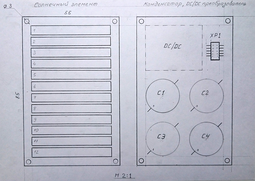
Photo 5.
On one side of the board are a solar battery, on the other hand an assembly of ionistors and a DC \ DC converter.
Specifications:
- Solar battery 12 cells, 6 V, current 60 mA (with full sun exposure);
- Ionistors total capacity 4; 6 or 16 Farads, permissible voltage 5.5 V, total self-discharge current, respectively, 120 \ 140 \ (not yet known) μA;
- A Schottky diode is dual with a drop in direct voltage of 0.15 V, used to decouple the power of the solar battery and ionistor;
- Layout dimensions: 55 x 85 mm (plastic VISA card);
- Estimated capacity without recharge from solar panels when installing capacitors 4; 6 or 16 Farads, is approximately 2 \ 3 \ 8 mA.
PS If you notice a typo, mistake or inaccuracy in the calculations, write us a personal message and we will quickly fix it.
To be continued ...
Author:
Chuyanov Vladimir