January 24, 2017 at 11:45
Simple Solder MK936. Soldering station for those who want it themselves
- Tutorial
Hello!
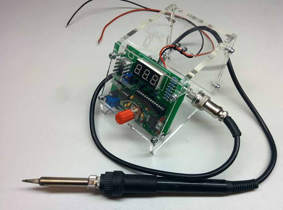
In this article we want to share with the public a project of a simple soldering station with temperature stabilization, which anyone can assemble without their own Arduino and electrical tape!
An ordinary soldering iron, which is connected directly to the network, simply heats constantly with the same power. Because of this, it warms up for a very long time and there is no way to regulate the temperature in it. You can dimming this power, but achieving a stable temperature and repeatability of soldering will be very difficult.
The soldering iron, prepared for use with the soldering station, has a built-in temperature sensor and this allows you to apply maximum power to it during heating, and then keep the temperature on the sensor. If you just try to adjust the power in proportion to the temperature difference, it will either warm up very slowly, or the temperature will cycle through. As a result, the control program must necessarily contain the PID control algorithm.
Obviously, delicate semiconductor electronics require minimizing thermal shocks during soldering, and simply the quality of the soldering itself increases with temperature stabilization, so sooner or later many hams come to the need to use soldering stations.
We tried to emphasize simplicity in repetition and cheapness. Our soldering station works with one of the cheapest soldering irons, and the rest of the items are in the assortment of many radio stores.
Also note that this is a digital soldering station with a microcontroller! As a rule, the cheapest soldering stations from popular manufacturers have an analog circuit.
The scheme is extremely simple. Atmega8 microcontroller is at the heart of everything. The signal from the thermocouple is fed to an operational amplifier with an adjustable gain (for calibration) and then to the ADC input of the microcontroller. To display the temperature, a seven-segment indicator with a common cathode was used, the discharges of which are connected through transistors. When turning the encoder knob BQ1, the temperature is set, and the rest of the time, the current temperature is displayed. When turned on, an initial value of 280 degrees is set. Determining the difference between the current and the required temperature, having recalculated the coefficients of the PID components, the microcontroller heats the soldering iron using PWM modulation.
To power the logical part of the circuit, a simple linear stabilizer DA1 at 5V is used.

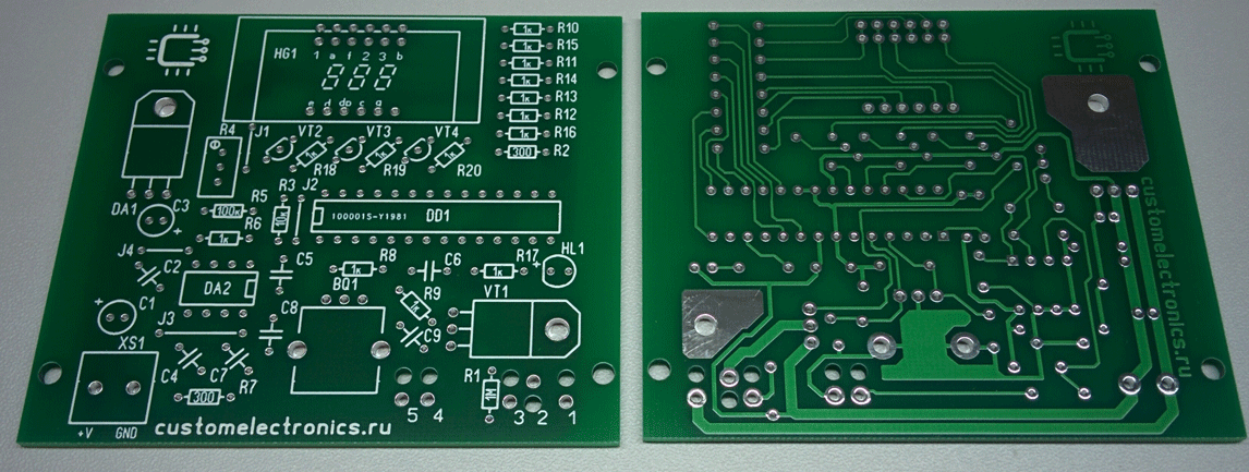
The printed circuit board is single-sided with four jumpers. The PCB file can be downloaded at the end of the article.
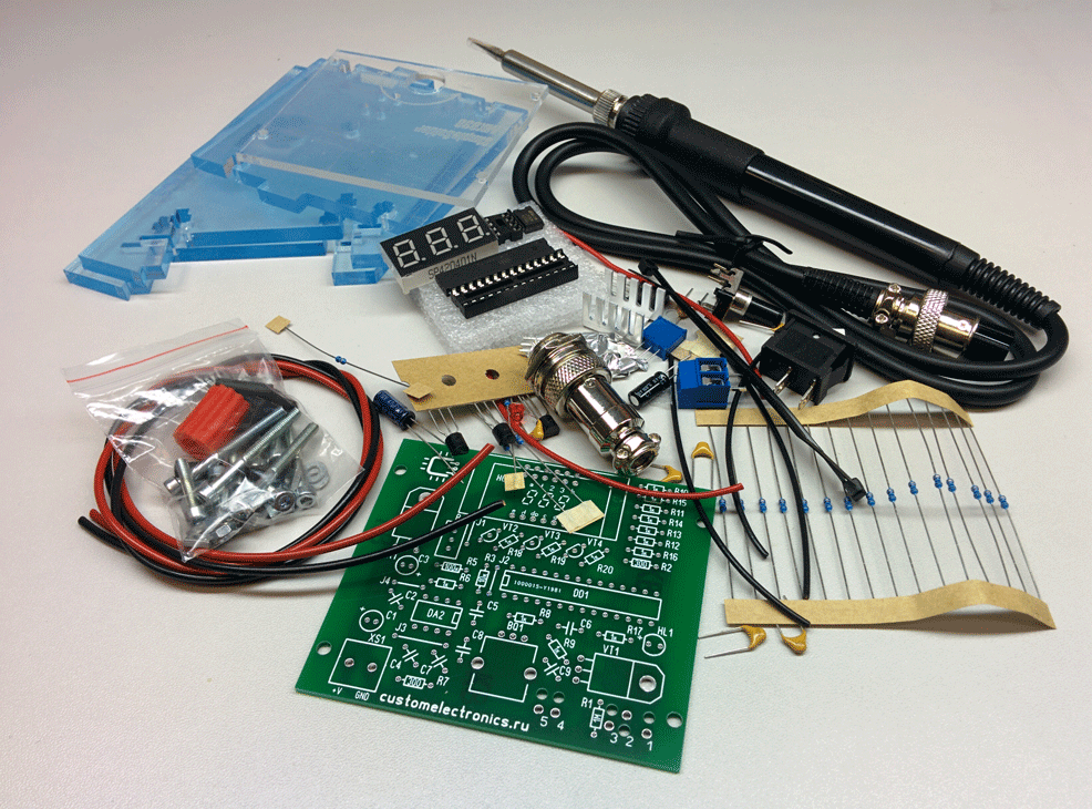
This is what a set of all the parts looks like:
It is most convenient to
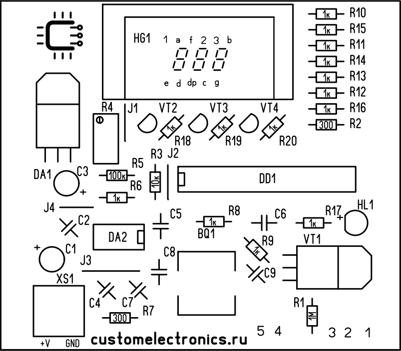
assemble a board according to the assembly drawing: Below is a detailed video about the installation process.
I want to draw attention to important points. It is necessary to observe the polarity of electrolytic capacitors, LEDs and the direction of installation of microcircuits. Do not install microcircuits until the case is completely assembled and the supply voltage is checked. Chips and transistors must be handled carefully so as not to damage them with static electricity.
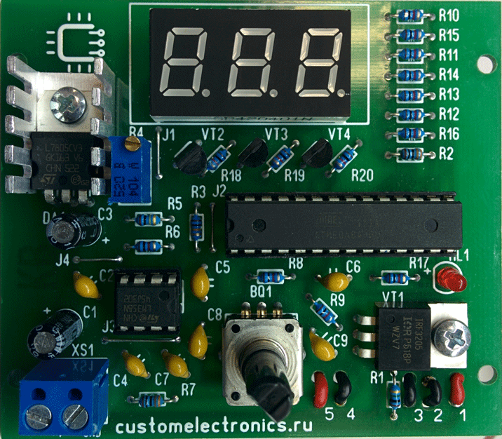
If the board is assembled correctly, it will look something like this:
For the soldering station, we also drew a file for cutting plexiglass. It can be handed over to this laser cutting company, and they will be able to produce the same housing for you.
The wiring diagram inside the case is not very complicated:
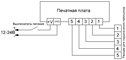
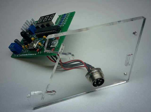
First you need to screw the connector to the right wall of the case, and only then solder the wires from the connector to the board. In this case, the contacts are soldered one to one. That is, the first to the first, the second to the second, etc. Please note that there are additional holes on the circuit board next to the mounting holes. Through them, wires can be passed for additional fixation.
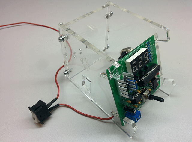
Next, you need to twist the left and rear walls of the housing with screws. Remember that plexiglass is a fragile material, and do not overtighten threaded joints!

In the next step, these two parts come together. Then you need to connect the power wires. Plus power is connected via a power switch. Please note that you do not need to install the front panel yet.
A HEX file for controller firmware will also be at the end of the article. The fuse bits should remain factory, that is, the controller will operate at a frequency of 1 MHz from the internal generator.
The first inclusion is made before installing the microcontroller and operational amplifier on the board. First of all, you need to check the power scheme. To do this, you need to apply a constant supply voltage from 12 to 24V to the board and check that there is a 5V supply voltage at the output of the stabilizer DA1. After that, when the power is off, observing the key position, the DA1 and DD1 microcircuits are installed in the sockets.
Now, when you turn it back on, the following functions should work: the temperature will be displayed on the indicator, the encoder will change it, the soldering iron will start to heat up, and the LED will signal the operation mode.
Next, you need to calibrate the soldering station.
The best option for calibration is the use of an additional thermocouple. It is necessary to set the required temperature and control it at the tip using a reference device. If the readings differ, then tighten the gain of the opamp with a multi-turn trimming resistor R4.
If there is no control measuring device at hand, then you can set the resistance of the resistor to about 90 kOhm and then select the temperature experimentally.
After the soldering station has been checked and calibrated, you can carefully install the front panel to prevent the parts from cracking.
For those who like to watch how others work:
This simple soldering station, made with the support of the Goods from China group to a Ham radio fan, will greatly change your impression of soldering if you only previously soldered with a regular network soldering iron!
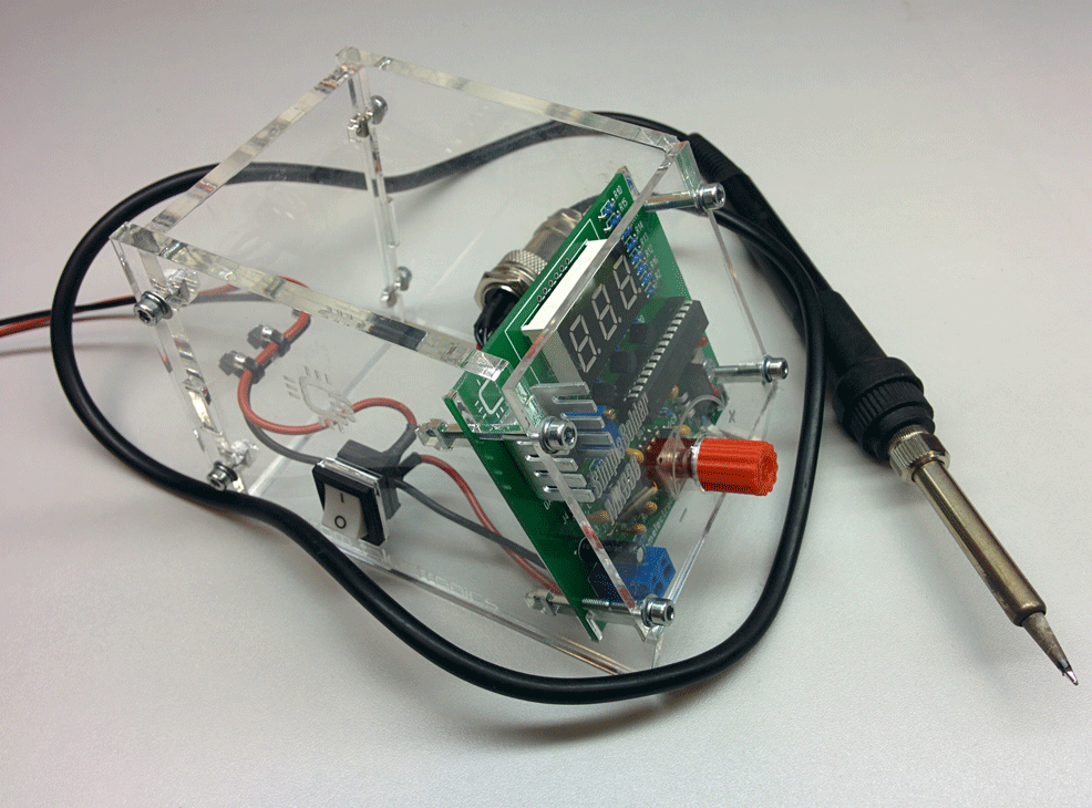
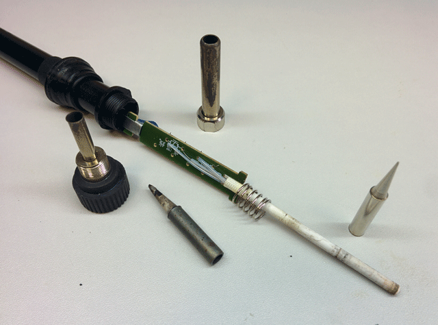
A few words should be said about the soldering iron. This is the easiest soldering iron with a temperature sensor. He has an ordinary nichrome heater and the cheapest sting. The sting is better to replace, for example, with this . Any one with an outer diameter of 6.5mm, an inner 4mm, and a shank length of 25mm will do.
All project files can be downloaded from our website . We will be very happy if they are useful to you.
Now we are working on the development of a soldering iron and we are very interested in your vision of the main characteristics of such a device so that you want to assemble it. We will be very grateful if you answer several questions of our profile (at the end you can see the answers of other users).
Thank you for your attention!
In this article we want to share with the public a project of a simple soldering station with temperature stabilization, which anyone can assemble without their own Arduino and electrical tape!
What is a soldering station
An ordinary soldering iron, which is connected directly to the network, simply heats constantly with the same power. Because of this, it warms up for a very long time and there is no way to regulate the temperature in it. You can dimming this power, but achieving a stable temperature and repeatability of soldering will be very difficult.
The soldering iron, prepared for use with the soldering station, has a built-in temperature sensor and this allows you to apply maximum power to it during heating, and then keep the temperature on the sensor. If you just try to adjust the power in proportion to the temperature difference, it will either warm up very slowly, or the temperature will cycle through. As a result, the control program must necessarily contain the PID control algorithm.
Obviously, delicate semiconductor electronics require minimizing thermal shocks during soldering, and simply the quality of the soldering itself increases with temperature stabilization, so sooner or later many hams come to the need to use soldering stations.
Features of our development
We tried to emphasize simplicity in repetition and cheapness. Our soldering station works with one of the cheapest soldering irons, and the rest of the items are in the assortment of many radio stores.
Also note that this is a digital soldering station with a microcontroller! As a rule, the cheapest soldering stations from popular manufacturers have an analog circuit.
Specifications
- Powered by a 12-24V DC voltage source
- Power Consumption, 24V Power Supply: 50W
- Soldering Iron Resistance: 12ohm
- Time to reach the operating mode: 1-2 minutes depending on the supply voltage
- Maximum temperature deviation in stabilization mode, not more than 5 degrees
- Control Algorithm: PID
- Temperature display on seven-segment display
- Heater Type: Nichrome
- Temperature Sensor Type: Thermocouple
- Temperature calibration option
- Setting the temperature using the eco-encoder
- LED to display the state of the soldering iron (heating / operation)
Circuit diagram
The scheme is extremely simple. Atmega8 microcontroller is at the heart of everything. The signal from the thermocouple is fed to an operational amplifier with an adjustable gain (for calibration) and then to the ADC input of the microcontroller. To display the temperature, a seven-segment indicator with a common cathode was used, the discharges of which are connected through transistors. When turning the encoder knob BQ1, the temperature is set, and the rest of the time, the current temperature is displayed. When turned on, an initial value of 280 degrees is set. Determining the difference between the current and the required temperature, having recalculated the coefficients of the PID components, the microcontroller heats the soldering iron using PWM modulation.
To power the logical part of the circuit, a simple linear stabilizer DA1 at 5V is used.
Printed circuit board
The printed circuit board is single-sided with four jumpers. The PCB file can be downloaded at the end of the article.
Component list
- BQ1. Encoder EC12E24204A8
- C1. Electrolytic Capacitor 35V, 10uF
- C2, C4-C9. Ceramic capacitors X7R, 0.1uF, 10%, 50V
- C3 Electrolytic capacitor 10V, 47mkF
- DD1. Microcontroller ATmega8A-PU in DIP-28 package
- DA1. 5V L7805CV stabilizer in TO-220 package
- DA2. Operational amplifier LM358DT in DIP-8 package
- HG1. Seven-segment three-digit indicator with a common cathode BC56-12GWA. Also, the board provides a seat for a cheap analogue .
- HL1. Any 20mA LED indicator with 2.54mm lead pitch
- R2, R7. 300 Ohm Resistors, 0.125W - 2pcs
- R6, R8-R20. 1kΩ Resistors, 0.125W - 13pcs
- R3. 10kΩ resistor, 0.125W
- R5. 100kΩ Resistor, 0.125W
- R1. 1MΩ Resistor, 0.125W
- R4. Trimmer Resistor 3296W 100kOhm
- VT1. IRF3205PBF field effect transistor in TO-220 package
- VT2-VT4. 3pcs BC547BTA transistors in TO-92 package
- XS1. Two-pin terminal block with terminal pitch 5.08mm
- Radiator for stabilizer FK301
- Block for the DIP-28 case
- Block for the DIP-8 case
- Soldering Iron Connector
- Power Switch SWR-45 BW (13-KN1-1)
- Soldering iron . We will write about him later
- Plexiglass parts for the case (files for cutting at the end of the article)
- Encoder knob. You can buy it, or you can print it on a 3D printer. File for downloading the model at the end of the article
- M3x10 screw - 2pcs
- Screw M3x14 - 4pcs
- Screw M3x30 - 4pcs
- M3 nut - 2pcs
- M3 square nut - 8pcs
- M3 washer - 8pcs
- M3 washer - 8pcs
- Also, assembly wires, cable ties and a heat shrink tube are required
This is what a set of all the parts looks like:
PCB mounting
It is most convenient to
assemble a board according to the assembly drawing: Below is a detailed video about the installation process.
I want to draw attention to important points. It is necessary to observe the polarity of electrolytic capacitors, LEDs and the direction of installation of microcircuits. Do not install microcircuits until the case is completely assembled and the supply voltage is checked. Chips and transistors must be handled carefully so as not to damage them with static electricity.
If the board is assembled correctly, it will look something like this:
Assembly and surface mounting
For the soldering station, we also drew a file for cutting plexiglass. It can be handed over to this laser cutting company, and they will be able to produce the same housing for you.
The wiring diagram inside the case is not very complicated:
First you need to screw the connector to the right wall of the case, and only then solder the wires from the connector to the board. In this case, the contacts are soldered one to one. That is, the first to the first, the second to the second, etc. Please note that there are additional holes on the circuit board next to the mounting holes. Through them, wires can be passed for additional fixation.
Next, you need to twist the left and rear walls of the housing with screws. Remember that plexiglass is a fragile material, and do not overtighten threaded joints!
In the next step, these two parts come together. Then you need to connect the power wires. Plus power is connected via a power switch. Please note that you do not need to install the front panel yet.
Controller firmware and settings
A HEX file for controller firmware will also be at the end of the article. The fuse bits should remain factory, that is, the controller will operate at a frequency of 1 MHz from the internal generator.
The first inclusion is made before installing the microcontroller and operational amplifier on the board. First of all, you need to check the power scheme. To do this, you need to apply a constant supply voltage from 12 to 24V to the board and check that there is a 5V supply voltage at the output of the stabilizer DA1. After that, when the power is off, observing the key position, the DA1 and DD1 microcircuits are installed in the sockets.
Now, when you turn it back on, the following functions should work: the temperature will be displayed on the indicator, the encoder will change it, the soldering iron will start to heat up, and the LED will signal the operation mode.
Next, you need to calibrate the soldering station.
The best option for calibration is the use of an additional thermocouple. It is necessary to set the required temperature and control it at the tip using a reference device. If the readings differ, then tighten the gain of the opamp with a multi-turn trimming resistor R4.
If there is no control measuring device at hand, then you can set the resistance of the resistor to about 90 kOhm and then select the temperature experimentally.
After the soldering station has been checked and calibrated, you can carefully install the front panel to prevent the parts from cracking.
Build Video
For those who like to watch how others work:
Conclusion
This simple soldering station, made with the support of the Goods from China group to a Ham radio fan, will greatly change your impression of soldering if you only previously soldered with a regular network soldering iron!
A few words should be said about the soldering iron. This is the easiest soldering iron with a temperature sensor. He has an ordinary nichrome heater and the cheapest sting. The sting is better to replace, for example, with this . Any one with an outer diameter of 6.5mm, an inner 4mm, and a shank length of 25mm will do.
Project files
All project files can be downloaded from our website . We will be very happy if they are useful to you.
Announcement
Now we are working on the development of a soldering iron and we are very interested in your vision of the main characteristics of such a device so that you want to assemble it. We will be very grateful if you answer several questions of our profile (at the end you can see the answers of other users).
Thank you for your attention!