GPS and bow side view. Multifunctional GPS Logger. Part 2
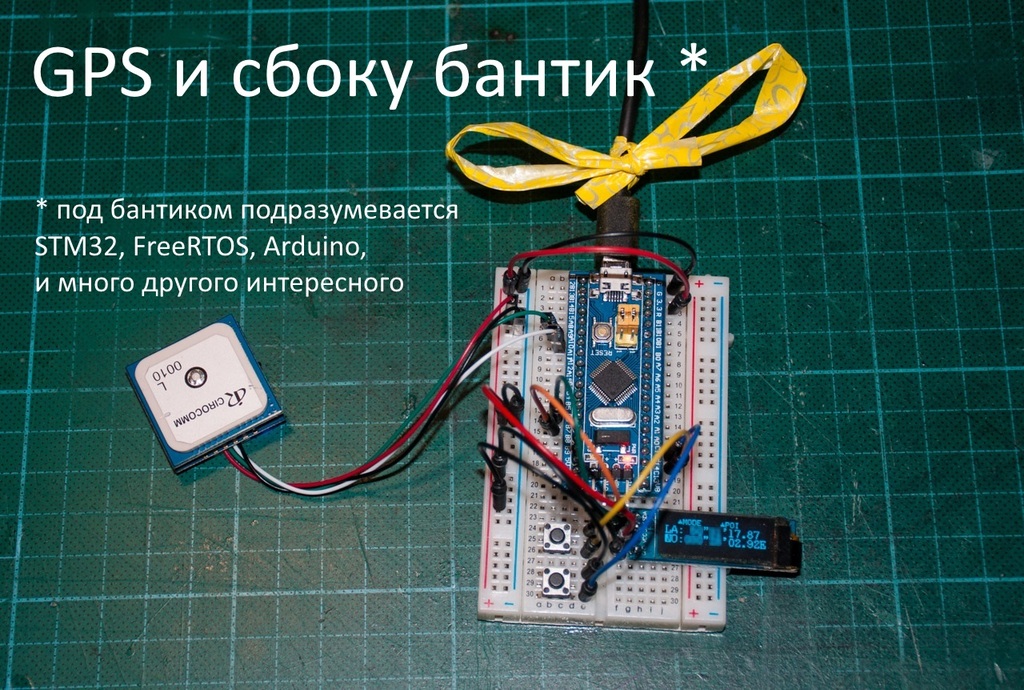
Hello! Some time ago, I got the idea to upgrade my faithful and beloved GPS logger Holux M241. One could look for something interesting in the market that could satisfy my needs. But it was more interesting to me to dig towards microcontrollers, the NMEA GPS protocol, USB and SD Card of wisdom, thereby building the device of my dreams.
What exactly am I building I described in detail in the first part . At that stage, I focused on technology - I felt for Arduino in the context of a relatively large project. It turned out there are a lot of nuances that are not particularly affected in ordinary tutorials. In the comments I received a lot of interesting input, for which I am very grateful to the readers. I hope today you will find something interesting.
This is the second article in a series. Like the previous one, it is a kind of construction magazine. I try to describe the technical decisions that I make as I work on the project. Today we will connect GPS. And also switch to more adult technologies - FreeRTOS and STM32 microcontroller. Well, as always, we will disassemble the firmware and see what is written there.
I ask for cat.
GPS
By this time, I already had the application framework. Everything was spinning on an Arduino Nano on an ATMega328 controller. It's time to connect my Beitan BN-880 GPS receiver .
Thoughts about UART
I have some bias towards UART as a low speed protocol from the last century. Of course, I understand the reason - the interface is as simple as 3 kopecks, it works on everything that moves. What else is needed? I also am biased towards text protocols - messages still need to be parsed. Why not drive data in binary form? Yes, even packages? All the same, their person does not read. And binary packages could greatly simplify processing. Well, I'm buzzing like that.
Seeing the legs of SDA and SCK sticking out of the module, I wanted to cling to them. I got hooked and ... I realized that getting data is not so easy. I don’t even know how. If UART is used, then the GPS receiver simply pours messages, and the receiver parses what it needs. I2C, however, transmission is initiated only by the host. Those. you need to form a request to get a response. But which one?
Guglezh on the topic of BN-880 I2C for a couple of hours did not give anything useful. People just use UART, and most of the links went to quadrocopter forums and mainly quadrocopter problems were discussed there.
It was not so easy to get on datasheets. Those. it was not clear what module to search for datasheet. By indirect evidence, I found out that the UBlox NEO-M8N module is responsible for GPS. It turned out that this thing is capable of such a number of features that my mother does not worry (there is even a built-in odometer and a logger there). But it was necessary to read no less than 350 pages.
Having looked back and forth through the datasheet, I realized that this module cannot be taken with a snap. I had to step on my throat and connect to an already tested UART. And then enter into another problem: there is only one UART on the arduino, and that one sticks out in the direction of the computer (upload firmware). I had to look towards the SoftwareSerial library.
I wrote the simplest “translator” of messages from the GPS port to UART.
Overflow
SoftwareSerial gpsSerial(10, 11); // RX, TX
void setup()
{
        	Serial.begin(9600);
        	gpsSerial.begin(9600);
}
void loop()
{
        	if (gpsSerial.available()) {
                    	Serial.write(gpsSerial.read());
        	}
}
Messages rained down, but the satellites could not catch. Although the time was right.
$GNRMC,203954.00,V,,,,,,,,,,N*6A
$GNVTG,,,,,,,,,N*2E
$GNGGA,203954.00,,,,,0,00,99.99,,,,,,*71
$GNGSA,A,1,,,,,,,,,,,,,99.99,99.99,99.99*2E
$GNGSA,A,1,,,,,,,,,,,,,99.99,99.99,99.99*2E
$GPGSV,1,1,02,02,,,21,08,,,09*7B
$GLGSV,1,1,00*65
$GNGLL,,,,,203954.00,V,N*5D
GPS lay for more than an hour at a window of 21 floors before it issued sane coordinates. Moreover, most of the review I have not closed high-rise buildings. There is a suspicion that some spraying is applied on the windows, which degrades the signal quality. In any case, satellites seem to be caught faster near an open window.
If there is a signal, then you can parse. The first library on the Internet was TinyGPSPlus. Connected not without hacks. In ArduinoIDE everything worked, but in Atmel Studio did not want to. I had to manually register the path to the library.
But here the problem got out. On simple sketches from TinyGPS + examples, everything worked. But when I connected it to my project with a display and buttons, everything broke. The device was noticeably stupid, clearly skipping the screen rendering. In the port monitor, I began to notice distorted messages from GPS.
The first assumption was that SoftwareSerial was very serious about consuming processor resources. So SoftwareSerial needs to be sent to the furnace, because it is not suitable for reliable communication with GPS (at least in the form in which it is in the examples). I even wanted to turn the circuit inside out: connect the arduins to the hardware UART, and use the software series for debugging (although it may not even be necessary to debug via UART if there is a screen). But with such a scheme, downloading the firmware via UART will fail. I had to get the USBAsp programmer.
But a little later I realized that the SoftwareSerial thing, though voracious, but in this case the problem is not at all in it, but in the drawing function. Drawing the current screen takes 50-75ms (plus a bit more for overhead). SoftwareSerial works on interrupt reception at the foot of the controller and should not consume much, in general. But it has a reception buffer of only 64 bytes, which even at a speed of 9600 are filled in 60 ms. It turns out that while the program is engaged in rendering the screen, part of the message from GPS already manages to pass by.
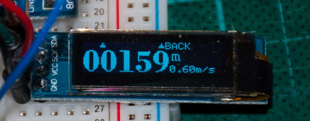
In the first half of the article I get a lot of text. I will dilute them with pictures. This screen displays the current height and vertical speed.
Armored
So. With the current approach, I ran into several limitations at once:
- Flash and RAM. Not so much was busy, but had to constantly remember this
- Just one UART. Additional SoftwareSerial significantly consumes processor resources.
- It is obviously impossible to do everything in one thread. You need to think about parallelizing tasks.
And it was also necessary to design with a view to the future - to me the connection of USB and SD cards is still shining.
After the previous part, I received a lot of comments that Arduino sucks and the future lies with ARM and STM32 controllers. I didn’t really want to leave the Arduino platform. As I said before, their framework is quite simple and straightforward, and I know ATMega controllers too.
At the same time, the transition to STM32 would most likely mean a change in the platform as a whole, the microcontroller, compiler, framework, libraries, IDEs and who knows what else. Those. almost everything at once. For the project, this would mean stopping completely, studying the documentation for a long time, studying various examples, and only then starting to rewrite everything from scratch.
I began to feel my way out of the situation, listening to the commentators of the first part. I wanted to find a solution that solved the restrictions, gave some groundwork for the future, but it did not require huge resources to move everything at once. Here are a few (generally independent) things with which I dig deeper.
- I connected a Sparkfun Pro Micro clone to ATMega32u4 (3.3V, 8MHz). In it, I wanted to feel the hardware USB. It took me quite a while to get this thing in general. The regular bootloader somehow did not really want to start like an arduino, and fuse bits were set in some mysterious way. As a result, with the help of USBAsp, I installed a bootloader from Arduino Leonardo and everything started up.
- The debug board came on ATMega64. It has 2 times more memory (and flash and RAM) and 2 uart. In principle, removes restrictions. Unfortunately, the circuit is not attached to the board and what kind of quartz is there is also not clear. I put it off for now.
- I tried to feel the FreeRTOS port under AVR. But here Kaku planted Atmel Studio. It turned out that she has 2 types of projects. In one, the studio works in Arduino mode, but in this case, almost nothing can be changed in the project settings. Those. it’s banal to not even put FreeRTOS in a subdirectory and register an include path. It can only put all the files in one pile, which would personally annoy me.
The second option is the Generic C ++ Executable project type. It is understood that you need to write in bare C ++. Here you can already configure as you wish. But firstly, you need to somehow fasten the Arduino framework, and secondly, it is not clear how to screw the firmware fill into the controller. Avrdude stubbornly did not want to overload the microcontroller in the bootloader (although I spied the command line on ArduinoIDE using ProcessMonitor). I have USBasp, but if there is a USB port, it’s not comme il faut on the board directly through the programmer. - Finally, I unzipped the comb to the board with the STM32F103C8T6 and installed the STM32duino according to the instructions . To my surprise, the LED blinker immediately started working. To my surprise, porting my project to a new controller took less than 10 minutes !!! Just change a couple of includes and fix the pin numbers.
That was what I needed. I got the power of STM32 (yes! The drawing function now took only 18ms!) And at the same time I could continue to use the arduino framework. This made it possible to continue work on the project, while, if necessary, smoothly dive into the new platform, reading the datasheet on the microcontroller in the subway.
The increase in flush is, in fact, a very ghostly improvement. The project as it occupied half the flash on the ATmega32, and occupies almost half on the new STM32 (okay, 26k out of 64k). So it wasn’t worth it to relax. Moreover, (as they write on the Internet), the compiled code is somewhat more sweeping and fills the flash faster than on AVR. So just in case I ordered a scarf with a 128k flash.
True, another surprise was waiting for me here. The people on the Internet writethat although the controller for the datasheet has a 64k flash on board, in fact you can use 128k. Those. ST seems to produce the same chip, only part of it is labeled as STM32F103C8T6, and the other as STM32F103CBT6 (the same controller, but with a 128k flash).
By the way (follow up after the previous article). In the ARM architecture, both flash and RAM are located in the same address space and are read in the same way. Therefore, dancing with a tambourine and declaring constants using PROGMEM are no longer needed. I cleaned it for the sake of clean code. Virtual function tables also do not need to be copied anywhere, because they are also in the same address space.
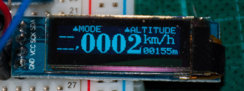
Another picture to dilute the text. From left to right: direction of movement (now we are not moving anywhere), current speed, current height. The screen is honestly lapped with a similar one in Holux M241
FreeRTOS
In the STM32duino bundle, the FreeRTOS port for my controller was also detected (and already two - 7.0.1 and 8.2.1). Examples with minimal edits also worked. So it was possible to switch to FreeRTOS without rewriting a significant part of the project.
After reading a couple of articles ( one , two ), I realized what power is now available to me - threads, mutexes, queues, semaphores and other synchronization. Everything is like on big computers. The main thing is to design everything correctly.
Despite the fact that the main problem I had was GPS, I still decided to start with something simpler - buttons. In a sense, FreeRTOS greatly simplifies the code - each thread can be engaged in some specific task, and, if necessary, notify other threads. So, the task of servicing buttons perfectly fell into this ideology - listen to your buttons and do not get distracted by anything. And how something is pressed - notify.
Side step
Although message flows and queues are cool, it seemed to me that the approach of polling buttons in a loop is not entirely correct - after all, there are interruptions in changing the value on the leg! Well, I also just wanted to try how it works on STM32 :)
Instead of prints, there should have been messages about the pressed button.
But to be honest, it turned out to be cumbersome (this is processing only one button) and even terribly buggy. Some kind of false positives were observed, or vice versa, no positives. It seems that the millis () function somehow worked incorrectly and could return the same values over a fairly long period of time.
static void selButtonPinHandler()
{
       	static uint32 lastInterruptTime = 0;
       	if(digitalRead(SEL_BUTTON_PIN)) // Falling edge
       	{
               	uint32 cur = millis();
               	uint32 pressDuration = cur - lastInterruptTime;
               	Serial.print("DePressed at ");
               	Serial.println(lastInterruptTime);
               	if(pressDuration > LONG_PRESS_TIMEOUT)
                       	Serial.println("Sel Long Press");
               	else
               	if(pressDuration > SHORT_CLICK_TIMEOUT)
                       	Serial.println("Sel Short Click");
               	else
               	{
                       	Serial.print("Click was too short: ");
                       	Serial.println((int)pressDuration);
               	}
       	}
       	lastInterruptTime = millis();
       	if(!digitalRead(SEL_BUTTON_PIN)) // Raising edge
       	{
               	Serial.print("Pressed at ");
               	Serial.println(lastInterruptTime);
       	}
}
void initButtons()
{
      	// Set up button pins
      	pinMode(SEL_BUTTON_PIN, INPUT_PULLUP); // TODO: using PullUps is an AVR legacy. Consider changing this to pull down
      	pinMode(OK_BUTTON_PIN, INPUT_PULLUP);  //  so pin state match human logic expectations
      	attachInterrupt(SEL_BUTTON_PIN, selButtonPinHandler, CHANGE);
}
Instead of prints, there should have been messages about the pressed button.
But to be honest, it turned out to be cumbersome (this is processing only one button) and even terribly buggy. Some kind of false positives were observed, or vice versa, no positives. It seems that the millis () function somehow worked incorrectly and could return the same values over a fairly long period of time.
Let me remind you. In the main cycle of the program, I had a large state machine that controlled the display and listened to the buttons. Adding some kind of logic was accompanied by redrawing half of the code, and to understand how it works just looking at the code was only a guru of programming state machines. But since I have RTOS, everything turned out much easier.
Button handler
// Pins assignment
const uint8 SEL_BUTTON_PIN = PC14;
const uint8 OK_BUTTON_PIN = PC15;
// Timing constants
const uint32 DEBOUNCE_DURATION = 1 / portTICK_PERIOD_MS;
const uint32 LONG_PRESS_DURATION = 500 / portTICK_PERIOD_MS;
const uint32 VERY_LONG_PRESS_DURATION = 1000 / portTICK_PERIOD_MS;
const uint32 POWER_OFF_POLL_PERIOD = 1000 / portTICK_PERIOD_MS; // Polling very rare when power is off
const uint32 IDLE_POLL_PERIOD = 100 / portTICK_PERIOD_MS;                	// And little more frequent if we are on
const uint32 ACTIVE_POLL_PERIOD = 10 / portTICK_PERIOD_MS;             	// And very often when user actively pressing buttons
QueueHandle_t buttonsQueue;
// Reading button state (perform debounce first)
inline bool getButtonState(uint8 pin)
{
	if(digitalRead(pin))
	{
		// dobouncing
		vTaskDelay(DEBOUNCE_DURATION);
		if(digitalRead(pin))
			return true;
	}
	return false;
}
/// Return ID of the pressed button (perform debounce first)
ButtonID getPressedButtonID()
{
	if(getButtonState(SEL_BUTTON_PIN))
		return SEL_BUTTON;
	if(getButtonState(OK_BUTTON_PIN))
		return OK_BUTTON;
	return NO_BUTTON;
}
// Initialize buttons related stuff
void initButtons()
{
	// Set up button pins
	pinMode(SEL_BUTTON_PIN, INPUT_PULLDOWN);
	pinMode(OK_BUTTON_PIN, INPUT_PULLDOWN);
	// Initialize buttons queue
	buttonsQueue = xQueueCreate(3, sizeof(ButtonMessage)); // 3 clicks more than enough
}
// Buttons polling thread function
void vButtonsTask(void *pvParameters)
{
	for (;;)
	{
		// Wait for a button
		ButtonID btn = getPressedButtonID();
		if (btn != NO_BUTTON)
		{
			// Button pressed. Waiting for release
			TickType_t startTime = xTaskGetTickCount();
			while(getPressedButtonID() != NO_BUTTON)
				vTaskDelay(ACTIVE_POLL_PERIOD);
			// Prepare message to send
			ButtonMessage msg;
			msg.button = btn;
			// calc duration
			TickType_t duration = xTaskGetTickCount() - startTime;
			if(duration > VERY_LONG_PRESS_DURATION)
				msg.event = BUTTON_VERY_LONG_PRESS;
			else
			if(duration > LONG_PRESS_DURATION)
				msg.event = BUTTON_LONG_PRESS;
			else
				msg.event = BUTTON_CLICK;
			// Send the message
			xQueueSend(buttonsQueue, &msg, 0);
		}
		// TODO: Use different polling periods depending on global system state (off/idle/active)
		vTaskDelay(ACTIVE_POLL_PERIOD);
	}
}
It turned out very compact and understandable. The functions are all very linear. We simply interrogate the buttons in the cycle and, based on the duration of the press, send the corresponding message.
I decided that I would have 3 types of press durations:
- Short to select the corresponding menu item
- Long for a special action (e.g. resetting a selected parameter)
- Very long press to turn the device on and off
By the way, I decided to connect the buttons not to plus, but to minus. Naturally, pull-up resistors were replaced by pull-down. I am not good at electronics and can be wrong here, but on the whole I was guided by the following considerations:
- In the released position of the button, the pin is pressed to zero, which means that the current does not flow (even if it is tiny)
- When reading a value from a pin, the value is not inverted: 1 if the button is pressed, 0 - released
ScreenManager has also been greatly simplified. There was no longer a need for a global display state. The rendering flow is exclusively for rendering and is controlled by messages from buttons. He simply waited for messages in line and worked out the received commands. Moreover, the wait loop itself was also made through the queue using the timeout in the xQueueReceive function. Those. the function waits for a message, and if nothing happens for a long time, it simply draws the screen as it is
Display stream
void vUserInteractionTask(void *pvParameters)
{
       	for (;;)
       	{
               	// Poll the buttons queue for an event. Process button if pressed, or show current screen as usual if no button pressed
               	ButtonMessage msg;
               	if(xQueueReceive(buttonsQueue, &msg, DISPLAY_CYCLE))
                       	processButton(msg);
               	// Do what we need for current state
               	drawDisplay();
       	}
}
It turned out, in my opinion, very elegant. Later, I added a screen off after a certain timeout (battery saving), but the code was not significantly complicated.
The processing of the buttons is also trivial - just parse the message and call the necessary function
Button Processing
void processButton(const ButtonMessage &msg)
{
      	if(msg.button == SEL_BUTTON && msg.event == BUTTON_CLICK)
               	getCurrentScreen()->onSelButton();
       	if(msg.button == OK_BUTTON && msg.event == BUTTON_CLICK)
               	getCurrentScreen()->onOkButton();
       	// TODO: process long press here
}
The showMessageBox () function has also become much simpler and now completely linear.
message box
void showMessageBox(const char * text)
{
        //Center text
        uint8_t x = 128/2 - strlen_P(text)*6/2;
        // Draw the message
        display.clearDisplay();
        display.setFont(NULL);
        display.drawRect(2, 2, 126, 30, 1);
        display.setCursor(x, 12);
        display.print(text);
        display.display();
        // Wait required duration
        vTaskDelay(MESSAGE_BOX_DURATION);
}
And finally. What kind of device is it if it does not have a blinking light? Need to fix it. No matter how funny it may be, it’s convenient to monitor by the blinking diode whether the device is still working or has been hanging long ago.
Hello FreeRTOS World!
void vLEDFlashTask(void *pvParameters)
{
	for (;;)
	{
		vTaskDelay(2000);
		digitalWrite(PC13, LOW);
		vTaskDelay(100);
		digitalWrite(PC13, HIGH);
	}
}
GPS again
Finally, it is time to torment GPS. Now there is no problem simultaneously listening to GPS and doing everything else. To start, I again wrote a transflector:
Overflow
void initGPS()
{
	// GPS is attached to Serial1
	Serial1.begin(9600);
}
void vGPSTask(void *pvParameters)
{
	for (;;)
	{
		while(Serial1.available())
		{
			int c = Serial1.read();
			gps.encode(c);
			Serial.write(c);
		}
		vTaskDelay(5);
	}
}
But there was a problem. Messages were formally parsed, but even the time to bite from there did not work. Smoking TinyGPS sources and documentation on the receiver showed a slight discrepancy between messages from the GPS module and the fact that the library can parse.
The UBlox module implements a certain extension of the NMEA protocol. Each message begins with a five-letter message identifier.
$GNGGA,181220.00,,,,,0,00,99.99,,,,,,*70The first 2 letters encode the subsystem that prepared the data: GP for GPS, GL for GLONASS, GA for GALILLEO. But if a combination of positioning systems is used, then the messages will start with GN.
The TinyGPS + library was not designed for this - it only knew how to parse GP messages. I had to fix it a bit - I changed the corresponding line in the parser and the time on the screen ran. Only now it all smelled like some kind of hack.
Comrade suggested an alternative - NeoGPS library. This is a much more feature-rich library. In addition to being able to parse messages with different prefixes, it also allows you to parse information about satellites (I personally like such things in GPS receivers). It is also worth noting that the library is terribly configurable - you can enable / disable parsing of individual messages and thereby regulate memory consumption depending on tasks.
It was not difficult to connect the library to stm32duino, though I still had to file a bit. But as always in the examples, everything is simple and clear, but in a real project it did not work right away. In particular, it was unclear at what point in time to correctly read from GPS. Here, for example, is an attempt to subtract satellite data.
Getting satellite information
for (;;)
{
	while(Serial1.available())
	{
		int c = Serial1.read();
		Serial.write(c);
		gpsParser.handle(c);
	}
       	if(gpsParser.available())
       	{
               	memcpy(satellites, gpsParser.satellites, sizeof(satellites));
               	sat_count = gpsParser.sat_count;
       	}
	vTaskDelay(10);
}
From time to time, the parser says that the data has arrived - take it. Coordinates always arrive normally, but with satellites a trouble. I take it, and there are zeros. Or not zeros. If we get lucky.
It turned out you had to carefully read the documentation. It's all about the design of the library. In the name of saving memory, the data is decomposed into variables during parsing. At what byte - byte came, updated the variable. Data comes in packets of several messages. The NeoGPS library needs to know when a new package starts in order to reset the internal variables. The configuration parameter LAST_SENTENCE_IN_INTERVAL is responsible for this.
//------------------------------------------------------
// Select which sentence is sent *last* by your GPS device
// in each update interval.  This can be used by your sketch
// to determine when the GPS quiet time begins, and thus
// when you can perform "some" time-consuming operations.
#define LAST_SENTENCE_IN_INTERVAL NMEAGPS::NMEA_RMC
So the RMC message comes to me the very first in the message packet. It turns out that my code could read partially parsed data (Perhaps it was the data of previous packages that had not yet been reset to zero). Or subtract zeros if read at the wrong time. It is treated quite simply: we indicate that in each packet from the GPS module the last message we have is GLL.
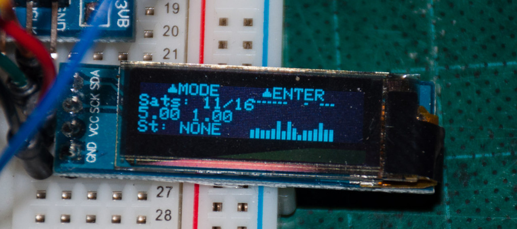
There are many satellites, but there is no fix and no. From top to bottom: the number of satellites (tracked vs untracked - I don’t know what this means), HDOP / VDOP, GPS signal status (caught / not caught)
By the way, with the library in the kit we found quite convenient functions for working with date and time. So, for example, it was very easy to fasten the time zone. I only store the time offset in minutes, and the rest is easy to calculate along the way.
Time correction according to the selected time zone
void TimeZoneScreen::drawScreen() const
{
	// Get the date/time adjusted by selected timezone value
	gps_fix gpsFix = gpsDataModel.getGPSFix();
	int16 timeZone = getCurrentTimeZone();
	NeoGPS::time_t dateTime = gpsFix.dateTime + timeZone * 60; //timeZone is in minutes
	...
	printNumber(dateBuf, dateTime.date, 2);
	printNumber(dateBuf+3, dateTime.month, 2);
	printNumber(dateBuf+6, dateTime.year, 2);
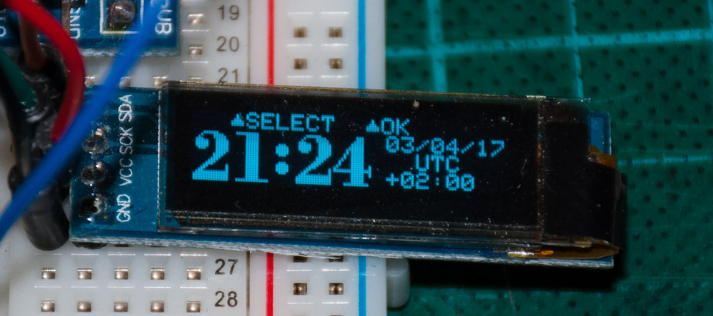
The time zone selection screen is honestly licked from Hulux
Model-View
When writing code, now we must not forget that we work in a multi-threaded environment. So, I have a stream that serves GPS: it listens to the Serial port, parses data from it byte by byte. Packets arrive once per second. The library knows when the next package starts and before accepting resets the internal variables. When the packet is fully received, the available flag is set. The data arrives for about half a second (there are 600 bytes at a speed of 9600). We still have half a second to pick them up before the transfer of the next packet begins.
The second stream deals with display maintenance. The rendering cycle occurs every 100-120ms. At each iteration, the program takes the actual data from the GPS and draws what the user now wants to see - coordinates, speed, altitude, or something else. And here a contradiction arises: the display stream always wants to receive data, whereas in the library it is only available for half a second, and then it is overwritten.
The solution is quite obvious: copy the data to yourself in an intermediate buffer. Naturally, the data in this buffer must be protected with a mutex ( mutex), otherwise the data may not be read correctly. But here is the problem. Data appears in the GPS stream, although rarely, but you can read it quickly (there are only one and a half hundred bytes after parsing), you don’t need to block the mutex for a long time. But the drawing function can work for a long time (up to 20ms). Blocking a mutex for such a long time, in general, is not very good. Although not fatal, in this particular project.
You can, of course, quickly lock the mutex, pick up the data in a local variable and release the mutex. But this is fraught with memory overruns. One and a half hundred bytes at 20 kilobytes is garbage, but personally the fact of triple buffering annoys me.
The buffer, by the way, had to be declared a global variable because it is very large and causes a stack overflow if it is declared in a function. Just in case, I wrote a larger stack to the drawing stream.
Reading satellite data in drawing function
NMEAGPS::satellite_view_t l_satellites[ NMEAGPS_MAX_SATELLITES ];
uint8_t l_sat_count;
void SatellitesScreen::drawScreen()
{
   	xSemaphoreTake(xGPSDataMutex, portMAX_DELAY);
   	memcpy(l_satellites, satellites, sizeof(l_satellites));
   	l_sat_count = sat_count;
   	xSemaphoreGive(xGPSDataMutex);
 	display.draw(....)
 	...
}
With instant values that you can get directly from the NMEA stream, everything is simple - the NeoGPS library reads them and decomposes them into variables. Each screen can simply read the corresponding variable (without forgetting about synchronization, of course) and display it on the screen. But with the variables that need to be calculated so simply did not work.
After much thought, I came to the classic model-view diagram.
The screen descendant objects are views — they display various data from the model, but the data itself does not produce it. All logic lies in the GPSDataModel class. He is responsible for storing instant GPS data (until new data arrives from NeoGPS). He is also responsible for computing new data, such as odometers or vertical speed. And last but not least, this class itself handles all the synchronization for its data.
Model class
const uint8 ODOMERTERS_COUNT = 3;
/**
 * GPS data model. Encapsulates all the knowledge about various GPS related data in the device
 */
class GPSDataModel
{
public:
	GPSDataModel();
	void processNewGPSFix(const gps_fix & fix);
	void processNewSatellitesData(NMEAGPS::satellite_view_t * sattelites, uint8_t count);
	gps_fix getGPSFix() const;
	GPSSatellitesData getSattelitesData() const;
	float getVerticalSpeed() const;
	int timeDifference() const;
	// Odometers
	GPSOdometerData getOdometerData(uint8 idx) const;
	void resumeOdometer(uint8 idx);
	void pauseOdometer(uint8 idx);
	void resetOdometer(uint8 idx);
	void resumeAllOdometers();
	void pauseAllOdometers();
	void resetAllOdometers();
private:
	gps_fix cur_fix; /// most recent fix data
	gps_fix prev_fix; /// previously set fix data
	GPSSatellitesData sattelitesData; // Sattelites count and signal power
	GPSOdometer * odometers[ODOMERTERS_COUNT];
	bool odometerWasActive[ODOMERTERS_COUNT];
	SemaphoreHandle_t xGPSDataMutex;
	GPSDataModel( const GPSDataModel &c );
	GPSDataModel& operator=( const GPSDataModel &c );
}; //GPSDataModel
/// A single instance of GPS data model
extern GPSDataModel gpsDataModel;
Because Since the model class is responsible for synchronizing data between streams, a mutex lives in it, which regulates access to the internal fields of the class. It was terribly inconvenient (and ugly) to use the bare xSemaphoreTake () / xSemaphoreGive (), so I drew a classic autocapturer (more precisely, even an auto-release).
Mutex locker
class MutexLocker
{
public:
	MutexLocker(SemaphoreHandle_t mtx)
	{
		mutex = mtx;
		xSemaphoreTake(mutex, portMAX_DELAY);
	}
	~MutexLocker()
	{
		xSemaphoreGive(mutex);
	}
private:
	SemaphoreHandle_t mutex;
};
Taking the current value is very simple. You just need to call the getGPSFix () function, which simply returns a copy of the data.
Data return
gps_fix GPSDataModel::getGPSFix() const
{
	MutexLocker lock(xGPSDataMutex);
	return cur_fix;
}
The client does not need to worry about locks and all that. Just take the data and draw as it should.
Client code
void SpeedScreen::drawScreen() const
{
	// Get the gps fix data
	gps_fix gpsFix = gpsDataModel.getGPSFix();
	// Draw speed
	...
	printNumber(buf, gpsFix.speed_kph(), 4, true);
The model class stores not only the most recent data (cur_fix), but also the previous value (prev_fix). So, calculating the vertical speed becomes a trivial task.
Vertical speed calculator
float GPSDataModel::getVerticalSpeed() const
{
	MutexLocker lock(xGPSDataMutex);
	// Return NAN to indicate vertical speed not available
	if(!cur_fix.valid.altitude || !prev_fix.valid.altitude)
		return NAN;
	return cur_fix.altitude() - prev_fix.altitude(); // Assuming that time difference between cur and prev fix is 1 second
}
It turned out to be very interesting with data about satellites. Data about satellites live in an array of NMEAGPS :: satellite_view_t structures. The array weighs 150 bytes and, as I already wrote, it needs to be copied several times. Not so critical in the presence of 20kb of RAM, but still this is three times 150 bytes each.
In the end, I realized that I do not need all the data, it is enough to copy myself only what is actually used. As a result, such a class was born.
Storage for satellite data
class GPSSatellitesData
{
	// Partial copy of NMEAGPS::satellite_view_t trimmed to used data
	struct SatteliteData
	{
		uint8_t snr;
		bool tracked;
	};
	SatteliteData satellitesData[SAT_ARRAY_SIZE];
	uint8_t sat_count;
public:
	GPSSatellitesData();
	void parseSatellitesData(NMEAGPS::satellite_view_t * sattelites, uint8_t count);
	uint8_t getSattelitesCount() const {return sat_count;}
	uint8_t getSatteliteSNR(uint8_t sat) const {return satellitesData[sat].snr;}
	bool isSatteliteTracked(uint8_t sat) const {return satellitesData[sat].tracked;}
};
This class is no longer so offensive to copy once again - it takes only 40 bytes.
The most difficult part of the circuit is the GPSOdometer class. As the name implies, he is responsible for all calculations related to the odometer functionality.
Odometer and Data Classes
// This class represents a single odometer data with no logic around
class GPSOdometerData
{
	// GPSOdometer and its data are basically a single object. The difference is only that data can be easily copied
	// while GPS odometer object is not supposed to. Additionally access to Odometer object is protected with a mutex
	// in the model object
	// In order not to overcomplicte design I am allowing GPS Odometer to operate its data members directly.
	friend class GPSOdometer;
	bool active;
	NeoGPS::Location_t startLocation;
	NeoGPS::Location_t lastLocation;
	float odometer;
	int16 startAltitude;
	int16 curAltitude;
	clock_t startTime;				///! When odometer was turned on for the first time
	clock_t sessionStartTime;		///! When odometer was resumed for the current session
	clock_t totalTime;				///! Total time for the odometer (difference between now and startTime)
	clock_t activeTime;				///! Duration of the current session (difference between now and sessionStartTime)
	clock_t activeTimeAccumulator;	///! Sum of all active session duration (not including current one)
	float maxSpeed;
public:
	GPSOdometerData();
	void reset();
	// getters
	bool isActive() const {return active;}
	float getOdometerValue() const {return odometer;}
	int16 getAltitudeDifference() const {return (curAltitude - startAltitude) / 100.;} // altitude is in cm
	clock_t getTotalTime() const {return totalTime;}
	clock_t getActiveTime() const {return activeTimeAccumulator + activeTime;}
	float getMaxSpeed() const {return maxSpeed;}
	float getAvgSpeed() const;
	float getDirectDistance() const;
};
// This is an active odometer object that operates on its odometer data
class GPSOdometer
{
	GPSOdometerData data;
public:
	GPSOdometer();
	// odometer control
	void processNewFix(const gps_fix & fix);
	void startOdometer();
	void pauseOdometer();
	void resetOdometer();
	// Some data getters
	GPSOdometerData getData() {return data;}
	bool isActive() const {return data.isActive();}
}; //GPSOdometer
This is the difficulty. The gps_fix object that comes to us from GPS may contain some data, and some may not. For example, the coordinate will arrive, but the height will not. And in the next fix it could be the other way around. Therefore, just saving gps_fix will not work. Every time you need to look at what is available in the new fix and what is not. Therefore, I had to fence a very complex algorithm, remember the coordinates, heights and time stamps separately.
Odometer data update every second
void GPSOdometer::processNewFix(const gps_fix & fix)
{
	Serial.print("GPSOdometer: Processing new fix ");
	Serial.println((int32)this);
	if(data.active)
	{
		Serial.println("Active odometer: Processing new fix");
		// Fill starting position if needed
		if(fix.valid.location && !isValid(data.startLocation))
			data.startLocation = fix.location;
		// Fill starting altitude if neede
		if(fix.valid.altitude && !data.startAltitude) // I know altitude can be zero, but real zero cm altutude would be very rare condition. Hope this is not a big deal
			data.startAltitude = fix.altitude_cm();
		// Fill starting times if needed
		if(fix.valid.time)
		{
			if(!data.startTime)
				data.startTime = fix.dateTime;
			if(!data.sessionStartTime)
				data.sessionStartTime = fix.dateTime;
		}
		// Increment the odometer
		if(fix.valid.location)
		{
			// but only if previous location is really valid
			if(isValid(data.lastLocation))
				data.odometer += NeoGPS::Location_t::DistanceKm(fix.location, data.lastLocation);
			// In any case store current (valid) fix
			data.lastLocation = fix.location;
		}
		// Store current altitude
		if(fix.valid.altitude)
			data.curAltitude = fix.altitude_cm();
		// update active time values
		if(fix.valid.time)
			data.activeTime = fix.dateTime - data.sessionStartTime;
		// update max speed value
		if(fix.valid.speed && fix.speed_kph() > data.maxSpeed)
			data.maxSpeed = fix.speed_kph();
	}
	 //Total time can be updated regardless of active state
	 if(fix.valid.time && data.startTime)
		data.totalTime = fix.dateTime - data.startTime;
}
In this place, the size of the flash increased sharply - by almost 10kb. A bunch of mathematical code crawled into the project - sines, cosines, tangents, square roots and all that jazz. It turned out that the legs are growing from the function NeoGPS :: Location_t :: DistanceKm () - all this is used in calculating the distance based on the coordinates. Gritting my teeth I had to agree, but I thought about the controller on the Cortex M4 - there it should be computed hardy.
Odometer control
void GPSOdometer::startOdometer()
{
	data.active = true;
	// Reset session values
	data.sessionStartTime = 0;
	data.activeTime = 0;
}
void GPSOdometer::pauseOdometer()
{
	data.active = false;
	data.activeTimeAccumulator += data.activeTime;
	data.activeTime = 0;
}
void GPSOdometer::resetOdometer()
{
	data.reset();
}
Note that there is no synchronization in the odometer class. This is because all synchronization takes place in the GPSDataModel class. I just didn’t want to drive a mutex in every object. But because of this, I had to complicate the odometer class itself and divide it into 2 classes: an object with data (GPSOdometerData) can be copied at the request of customers, while a control object (GPSOdometer) is created once for each odometer. Because of this, I also had to make one class a friend to another. Perhaps I will revise this design in the future.
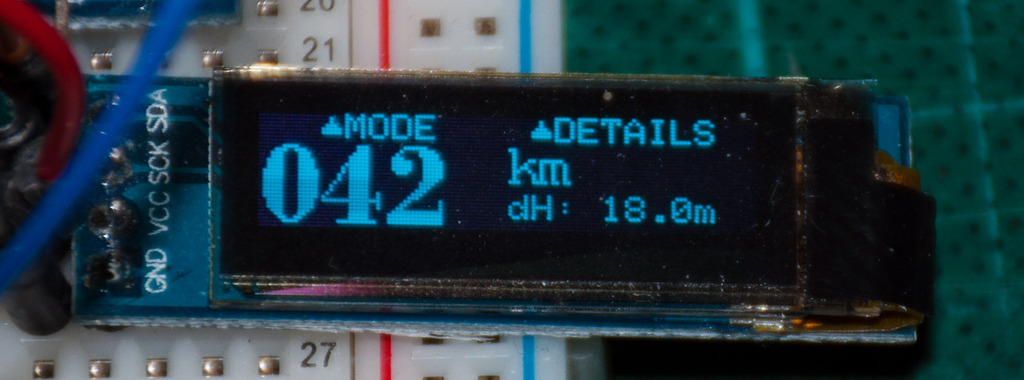
This is how the main odometer screen looks. I have not added a dot to the font yet - it should show 0.42km. The height difference is also displayed - lying in place on the windowsill, you can easily change by 18 meters or more.
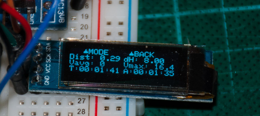
Other useful options that can be displayed by the odometer. On one screen, everything did not even fit - I will make 2 or even 3 screens.
GPSDataModel can control all odometers at once. This feature was suggested in the comments and should be convenient - I went to the cafe, turned off all odometers at once. Came out - turned them on again.
Manage odometers all at once
void GPSDataModel::resumeAllOdometers()
{
	MutexLocker lock(xGPSDataMutex);
	if(odometerWasActive[0])
		odometers[0]->startOdometer();
	if(odometerWasActive[1])
		odometers[1]->startOdometer();
	if(odometerWasActive[2])
		odometers[2]->startOdometer();
}
void GPSDataModel::pauseAllOdometers()
{
	MutexLocker lock(xGPSDataMutex);
	odometerWasActive[0] = odometers[0]->isActive();
	odometerWasActive[1] = odometers[1]->isActive();
	odometerWasActive[2] = odometers[2]->isActive();
	odometers[0]->pauseOdometer();
	odometers[1]->pauseOdometer();
	odometers[2]->pauseOdometer();
}
void GPSDataModel::resetAllOdometers()
{
	MutexLocker lock(xGPSDataMutex);
	odometers[0]->resetOdometer();
	odometers[1]->resetOdometer();
	odometers[2]->resetOdometer();
	odometerWasActive[0] = false;
	odometerWasActive[1] = false;
	odometerWasActive[2] = false;
}
Again FreeRTOS'im
In order to study the possibilities of FreeRTOS, I tried to see how much time the processor actually spent in computing. You can use ApplicationIdleHook for evaluation .
Any RTOS has a so-called idle stream. If the processor has nothing to occupy itself with, a certain endless cycle is spinning in a separate task with the lowest priority. FreeRTOS allows you to add some utility to this endless loop and run this hook. The idea of measuring processor load is that the more time a processor spends in an idle thread, the less it is loaded with other (useful) work.
On the Internet, I found several approaches for measuring processor load.
Some guys suggested in the Idle Hook function to turn a certain counter and measure the speed with which it "wound". To translate this into percent, you need to divide the resulting speed into some reference value.
But where to get this reference speed? To do this, you need to pay off all other flows and measure only the speed of the counter in an unloaded system. It is possible, for example, to make a delay of 1-2 seconds at the start for measurements, but personally it terribly infuriates me when fairly simple devices “load” for 5-10 seconds (for example, soap cameras. Grrrr).
In another embodiment, it was suggested that the Internet start a separate timer and reload the entry and exit macros into the context of the stream. The idea is to measure the difference in timer values at the input and output of each stream and from this draw a conclusion about the processor load.
Yes, I heard about Run Time Stats on the FreeRTOS system. But, as the instruction says, it is intended for another. This function allows for debiting purposes to get downloads for each individual thread and for the entire period of the application. I wanted to measure the instant processor load.
I decided to try the next option. I don’t know how correct this is and whether it will even work when I fasten the sleep mode. But at this stage it works pretty well.
load measurement
static const uint8 periodLen = 9; // 2^periodLen ticks - 512 x 1ms ticks
volatile TickType_t curIdleTicks = 0;
volatile TickType_t lastCountedTick = 0;
volatile TickType_t lastCountedPeriod = 0;
volatile TickType_t lastPeriodIdleValue = 0;
volatile TickType_t minIdleValue = 1 << periodLen;
extern "C" void vApplicationIdleHook( void )
{
   	// Process idle tick counter
   	volatile TickType_t curTick = xTaskGetTickCount();
   	if(curTick != lastCountedTick)
   	{
         	curIdleTicks++;
         	lastCountedTick = curTick;
   	}
   	// Store idle metrics each ~0.5 seconds (512 ticks)
   	curTick >>= periodLen;
   	if(curTick >  lastCountedPeriod)
   	{
         	lastPeriodIdleValue = curIdleTicks;
         	curIdleTicks = 0;
   	   	lastCountedPeriod = curTick;
         	// Store the max value
         	if(lastPeriodIdleValue < minIdleValue)
                	minIdleValue = lastPeriodIdleValue;
   	}
}
A function can be called very often, many times in one tick of the system (system tick is 1ms). Therefore, the first block is responsible for counting the ticks (not calls) in which the hook was called. The second block stores the counter every 512 system ticks.
CPU utilization is the ratio of the number of non-idle ticks to the total number of ticks in the measured interval.
Value calculation
float getCPULoad()
{
   	return 100. - 100. * lastPeriodIdleValue /  (1 << periodLen);
}
float getMaxCPULoad()
{
   	return 100. - 100. * minIdleValue /  (1 << periodLen);
}
Yes, this may not be entirely accurate. But in general, to get some rough estimate of the load on the system, it will take a ride. I am going to use these indicators to lower the frequency of the controller to reduce consumption.
By the way, in normal mode, the download was about 12.5% and jumps to 15.5% when GPS data comes in and needs to be parsed. When the display is off (although GPS continues to be parsed), loading drops to 0. This is strange. Apparently GPS parsing actually takes less than a tick, so every tick after that falls into the idle task. A 3% surge in loading is probably not due to data parsing itself, but to sending them to another stream.
Although perhaps I’ve just messed up somewhere here.
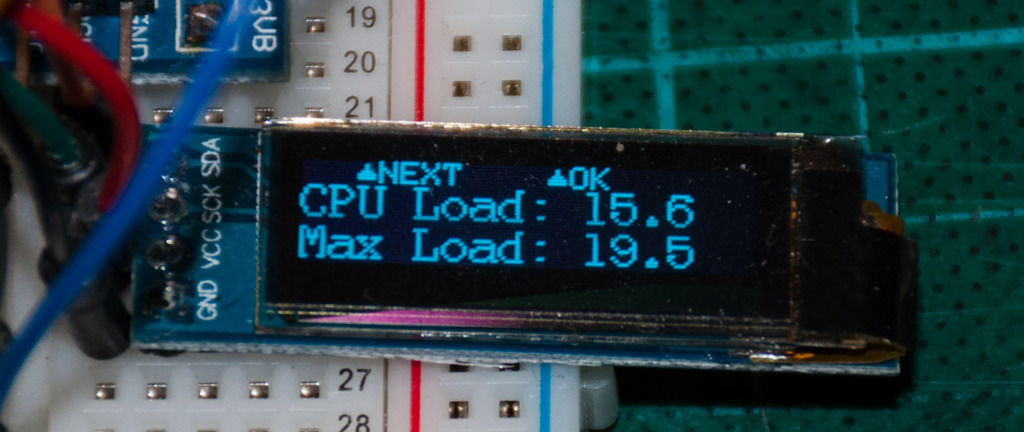
Indications of the current and maximum processor load. The screen itself will be hidden somewhere in the depths of the settings menu.
Different
In this section, I collected individual problems that I solved at different stages of the project. Without any particular sequence.
- The sprintf library implementation takes a lot - 13k. I had to write my implementation. I wrote a small classic that implements the Printable interface. So you can “print” numbers with the desired formatting on the screen and even in Serial. It turned out pretty nice and just a couple of code screens.Float formatter
/// Helper class to print float numbers according to specified options class FloatPrinter : public Printable { char buf[8]; // Print numbers no longer than 7 digits including sign and point symbols uint8 pos; // position in the buffer with the first meaningful char public: FloatPrinter(float value, uint8 width, bool leadingZeros = false, bool alwaysPrintSign = false); virtual size_t printTo(Print& p) const; }; FloatPrinter::FloatPrinter(float value, uint8 width, bool leadingZeros, bool alwaysPrintSign) { // reserve a space for sign uint8 minpos = 0; if(alwaysPrintSign || value < 0) minpos++; // absolute value to print, deal with sign later float v = value; if(v < 0) v = 0. - v; // floating point position will depend on the value uint8 precision = 0; if(v < 100) { v *= 10; precision++; } if(v < 100) // doing this twice { v *= 10; precision++; } uint32 iv = v + 0.5; // we will be operating with integers // Filling the buffer starting from the right pos = width; buf[pos] = '\0'; bool onceMore = true; // Print at least one zero before dot while((iv > 0 || onceMore) && (pos > minpos)) { pos--; onceMore = false; // Fill one digit buf[pos] = iv % 10 + '0'; iv /= 10; // Special case for printing point // Trick used: if precision is 0 here it will become 255 and dot will never be printed (assuming the buffer size is less than 255) if(--precision == 0) { buf[--pos] = '.'; onceMore = true; } } //Print sign if(value < 0) buf[--pos] = '-'; else if (alwaysPrintSign) buf[--pos] = '+'; } size_t FloatPrinter::printTo(Print& p) const { return p.print(buf+pos); } - Пока я писал эту функцию нужно было ее как то проверять. Как-то так получилось, что у меня на домашнем компе не установлено никаких компиляторов или IDE кроме ардуино (и Atmel Studio). Поэтому код я писал в браузере на cpp.sh. Я написал небольшую обертку вокруг этого кода, которая запускает функцию с разными параметрами и проверяет результат. Получился такой себе вариант юнит теста, только без необходимости создавать проект, втягивать туда какой нибудь тестовый фреймворк и все такое.
Конечно же есть и минусы. Код теста нужно синхронизировать с “продакшен” кодом методом копи-пасты. Благо это не нужно делать очень часто.типа юнит тест#include#include typedef unsigned char uint8; typedef unsigned int uint32; // This is some kind of a unit test for float value print helper. Code under the test is injected into a test function below via simple copy/paste from FloatPrinter constructor. // This allows executing the code right at C++-in-browser service (such as http://cpp.sh) // I just did not want to set up a development toolchain, create a project file, deal with external libraries, do a dependency injection into tested class, etc :) void test(const char * expectedValue, float value, uint8 width, bool leadingZeros = false, bool alwaysPrintSign = false) { char buf[9]; uint8 pos; printf("Printing %f... ", value); //////////////////////////////////////////////////////// // Begin copy from FloatPrinter //////////////////////////////////////////////////////// //////////////////////////////////////////////////////// // End copy from FloatPrinter //////////////////////////////////////////////////////// if(strcmp(expectedValue, buf+pos) == 0) { printf("%s - PASSED\n", buf+pos); } else { printf("%s - FAILED\n", expectedValue); printf("Got: %s\n", buf+pos); printf("Buffer: "); for(int i=0; i<9; i++) printf("%2x ", buf[i]); printf("\npos=%d\n\n", pos); } } int main() { test("0", 0., 4); test("0.10", 0.1, 4); test("0.23", 0.23, 4); test("4.00", 4., 4); test("5.60", 5.6, 4); test("7.89", 7.89, 4); test("1.23", 1.234, 4); test("56.8", 56.78, 4); test("56.8", 56.78, 5); test("123", 123.4, 4); test("568", 567.8, 5); test("12345", 12345., 6); test("-0.10", -0.1, 5); test("-0.23", -0.23, 5); test("-4.00", -4., 5); test("-5.60", -5.6, 5); test("-7.89", -7.89, 5); test("-1.23", -1.234, 5); test("-56.8", -56.78, 5); test("-56.8", -56.78, 6); test("-123", -123.4, 5); test("-568", -567.8, 6); test("-12345", -12345., 7); } - Использовать Serial.print в конструкторах нельзя — МК уходит в циклический ребут. Скорее всего USB Serial инициализируется несколько позже конструкторов статически размещенных объектов. Из-за этого вызывается неинициализированный код.
- Стандартный синглтончик Майерса принес в проект такое огромное количество кода, что мама не горюй. Более 40к! Там были и эксепшены, и type info, какие то куски C++ ABI и много чего я и слыхом не слыхивал за десятилетия работы программистом.ага, вот эти ребята
GPSDataModel & GPSDataModel::instance()
{
   	static GPSDataModel inst;
   	return inst;
}
Так что плюсы плюсами, а объекты пришлось разместить в глобальных переменных, прописав где нужно ссылки через extern. - Шрифты. В прошлой части я уже писал, что шрифты пришлось готовить самостоятельно. У меня есть скрипт, который из картинки генерит нужный код. Но в изначальном варианте данные лежали не в упакованном формате, а потому занимали больше места чем могли бы. Я доработал скрипт, и шрифты удалось упаковать, тем самым выиграв чуток флеша.
Так, шрифт 8х12 похудел с 850 до 732 байта, а шрифт 16х22 (нарисовал самостоятельно используя Bodoni MT) уменьшился с 474 до 408. В этом шрифте только цифры, потому он так мало занимает. - Изначально шрифты у меня располагались в хедере в виде константных массивов. Хедеры инклудятся в соответствующие cpp-шники где я рисую этими шрифтами. Так вот, сцуко, компилер для каждого цппшника дублирует фонты. Я переместил фонты в cpp файл и объем флеша сразу сократился на 9к. 9 килобайт за константу в хедере! 9 килобайт, Карл! Вот и верь после этого отлаженным компиляторам!
- С удивлением обнаружил, что у HardwareSerial нет метода attachInterrupt. У оригинального ардуино его, кстати, тоже нет. Можно использоваться NeoSWSerial, который рекомендуют в документации NeoGPS, но это как то странно использовать софтварный UART при наличии целой кучи хардварных.
Я тут просто начитался документации по STM32 — DMA и все такое. Подумал, может и мне пригодится такой режим в целях экономии батареи. Ведь сейчас хоть и со sleep()’ами, но все таки идет постоянный опрос “а не пришло ли чего из GPS?” - Пришлось озадачится вопросами UX дизайна. Хочется вывести на экран кучу разной информации, но пикселей не так много. Даже с использованием самого маленького шрифта влазит не больше 3 строк по 21 символу.
Так, вся информация по одометру попросту не влазит на один экран. И на 2 тоже. Пришлось сделать один основной экран с большими и красивыми буквами. А если пользователю интересно, то в режиме подменю можно будет доступится до более детальной информации на нескольких экранчиках. - GPS. Библиотека NeoGPS предоставляет некий статус соединения. В стиле “нет сигнала” -> “получили только время” -> “получили 2D Fix” -> “получили 3D Fix”. Возможно это работает с каким нибудь другим GPS модулем, но не с моим. У меня работают только первый и последний пункты.
- GPS. Хотел побырику раздобыть параметр точности координаты. А не тут-то было. В явном виде получить его не удалось, а HDOP/VDOP это только косвенные показатели точности. Буду очень благодарен за толковое разъяснение по этим метрикам.
- Высота может быть отрицательная. Очень удивился когда увидел высоту 65000м, оказалось ГПС после включения давал высоту -500м. Пришлось сделать специальный кейс у себя в коде для корректного отображения отрицательных высот.
- Скорость позиционирования оставляет желать лучшего. Реклама гласит Time To First Fix < 30 секунд, но это, по всей видимости, означает поимку первого спутника, а не первых координат. Время регистрируется почти сразу после включения. А вот координат приходится ждать пару минут. Даже GPS включался несколько минут назад.
Возможно модуль не нужно выключать «из розетки» а переводить в какой нибудь глубокий сон. Батарейка на модуле намекает. - Точность также под вопросом. Высота регистрируется неправильно: +-50м, и только потом медленно ползет куда надо. Да и потом заметно плавает
- При плохом приеме могут возникать большие скачки скорости до 150км/ч, а сам модуль может накрутить на до 7км за час. Нужно будет проверить где нибудь в поле.
Оптимизируем
Finally, a few words about optimizing consumption. Yes, the controller is more powerful, but the problems are the same. You need to carefully monitor the memory consumption because one careless movement can add a couple of kilos to the firmware.
As expected, on STM32 all the same problems got out as on AVR.
- the constants that forgot to write the word const are still placed in RAM (there will be half a half of such constants there. Mostly USB descriptors)
- 512 bytes of an adafruit picture that is loaded into the display buffer and never shown.
- functions for working with SPI, although nothing is connected to me via SPI - 512 bytes
- any garbage from NeoGPS - calculation of a leap year and all that jazz. Someone indirectly uses - 300 bytes
- TwoWire class (manual implementation of I2C). It’s definitely not used, but the linker does it anyway - 650 bytes
- код по работе с АЦП. Пока не используется, но будет когда-то для измерения параметров батареи. Пока не трогал.
The list is far from complete. It seems that if some object (the same TwoWire) is declared in the header, then the linker attracts it to the project, regardless of whether it is actually used or not. Perhaps this can be adjusted by the linker settings, but the Arduino build system does not allow you to configure anything. In the end, I just commented out the TwoWire class in the Wire library and everything compiled without problems.
SPI code is a bit trickier. The fact is that the creators of the Adafruit_SSD1306 library
Everything else is small. Where I could - patched libraries, placed const where necessary. But basically left everything as it is. At the moment, 55kb of flash is occupied, of which my code is slightly less than 7k - everything else is a library. Here is a little more detailed, if anyone is interested
Section memory consumption
| Name | Size |
| .text section (Code in ROM) | |
| System stuff | 320 |
| My code | 212 |
| Neogps | 4056 |
| Adafruit SSD1306 | 3108 |
| FreeRTOS | 3452 |
| Arduino: Wire Library (I2C) | 296 |
| My code | 6744 |
| Board init / system stuff | 788 |
| libmaple | 3778 |
| Arduino (HardwareSerial, Print) | 1978 |
| libmaple | 280 |
| libmaple USB CDC | 2216 |
| libmaple USB CoreLib | 2388 |
| math | 12556 |
| libc (malloc / free, memcpy, strcmp) | 3456 |
| Total: | 45628 |
| .data section (RAM) | |
| libmaple constants & tables | 820 |
| USB stuff & descriptors (after cleanup) | 84 |
| Impure data (WTF? Used in FreeRTOS) | 1068 |
| malloc stuff | 1044 |
| Total: | 3016 |
| .rodata section (constants in ROM) | |
| NeoGPS constants | 140 |
| Adafruit_SSD1306 constants | 76 |
| default font | 1280 |
| vtables | 120 |
| Monospace8x12 font | 1512 |
| vtables | 42 |
| My classes data + vtables | 886 |
| TimeFont | 528 |
| My classes data + vtables | 168 |
| Arduino + libmaple stuff | 792 |
| USB descriptors | 260 |
| Math constants | 552 |
| Total: | 6356 |
| .bss section (Zeroed variables in RAM) | |
| stuff | 28 |
| display buffer | 512 |
| Heap | 8288 |
| FreeRTOS | 192 |
| My data | 868 |
| libmaple + arduino | 168 |
| usb | 548 |
| malloc stuff | 56 |
| usb | 60 |
| Total: | 10720 |
Потребление ОЗУ моими классами и переменными
| name | Size |
| CurrentPositionScreen::drawScreen() const::longtitudeString | 17 |
| CurrentPositionScreen::drawScreen() const::latitudeString | 19 |
| timeZoneScreen | 12 |
| odometer1 | 52 |
| odometer0 | 52 |
| gpsDataModel | 192 |
| odometer2 | 52 |
| gpsParser | 292 |
| lastPeriodIdleValue | 4 |
| curIdleTicks | 4 |
| lastCountedTick | 4 |
| lastCountedPeriod | 4 |
| debugScreen | 12 |
| speedScreen | 12 |
| positionScreen | 8 |
| timeScreen | 12 |
| screenStack | 20 |
| rootSettingsScreen | 8 |
| display | 40 |
| satellitesScreen | 12 |
| screenIdx | 4 |
| odometerScreen | 24 |
| altitudeScreen | 8 |
It is worth noting that the generated code itself is quite compact (albeit more ambitious than on AVR). I do not know the assembler ARM, but it looks like this. The optimizer, by the way, doesn’t mix the code as famously as in the case of AVR. All functions are grouped by their original location - this greatly facilitates reading.
But the libc library functions take up indecently. I already wrote about 12k on sprintf. That's not all. Functions like strcmp or memset occupy several screens of assembler code. I would like to see what they do there. I even downloaded the newlib sources where these functions are implemented. But there are assembler and written. With a minimum of comments. So it did not become clearer. It could be rewritten independently, but, in my opinion, rewriting such things is blasphemy.
Most of all, of course, are trigonometric functions and floating-point mathematics. But if you consider that all sorts of calculations are the essence of the device, then you have to put up with it.
The only large and incomprehensible part for me is malloc / free. I obviously do not use it in my code. FreeRTOS has its own implementation. Where it climbs is unclear. I did not find any calls. I tried to roll back to the very first commit when I sorted my project on STM32 - this code was already in the firmware. I will say more. If you connect Adafruit_GFX in an empty project, there will already be malloc. It is unlikely that the library is to blame here - I connected a completely innocent header with tidedefs. Most likely these are some kind of jambs of the build system.
Otherwise, everything looks pretty decent.
Afterword
I put a bottle to someone who has read up to this place (C) a student bike.
The project is slowly but surely moving towards the goal. In this part, I moved to a more powerful ARM / STM32 platform and, to be honest, I liked it damnly. As before, there is a lot of misunderstanding of how everything works, the datasheet is read by 20 percent. But this does not prevent us from moving on.
Another major step I took was moving to FreeRTOS. The code has become significantly simpler and more structured. And most importantly, it is easy to expand further.
Finally, I connected the GPS receiver. Using the NeoGPS library, I was able to get all the necessary data and display it on the appropriate screens. True, I had to tinker with the invention of an internal data model.
Now I have run into problems with the Arduino build system. It is good for small projects, but it presses me literally from all sides. The system is practically not configured and many things happen without my knowledge. In addition, I have a lot of questions on the part of configuration management: how to version changes in libraries? How to sort your source into directories to make it convenient? How to upload this to the repository so that colleagues can work with it? In general, this will be the first priority in future work.
My sensation only feels that changing the build system will entail other things. Most likely, you will have to move from Atmel Studio to CooCox or another IDE. Perhaps the compiler will change. You may have to abandon the Arduino framework. It’s hard to say what it will pull.
Well, then there will be an SD card connection, power management, USB Mass Storage Device and a lot of interesting things.
If anyone liked it, I invite you to join the project. I will also be happy with constructive comments - they help me a lot.
→ Proct page on github