September 9, 2016 at 18:55
Planting a Helicopter Blindly: A Synthetic Vision Technology Review
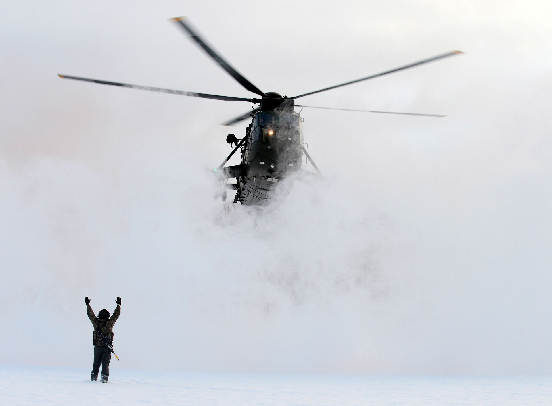
Landing on an unprepared site is one of the most difficult elements of helicopter piloting; it is associated with an increased risk of an accident and human casualties. The need for landing on unprepared sites arises primarily in military aviation: landing, evacuation, delivery of ammunition and cargo in combat conditions - in these flight missions one often has to land a helicopter in an unprepared or unexplored landing zone (or hover directly above it).
One of the key problems when landing on unprepared sites is the conditions of insufficient visibility (UNV, Eng.degraded visual environment, DVE). UNV refers to the low or zero optical visibility of the outside environment due to any of the following factors or a combination of these: low light, adverse weather conditions (fog, blizzard, etc.), a vortex of solid particles lifted by the helicopter rotor. The latter factor is particularly dangerous.
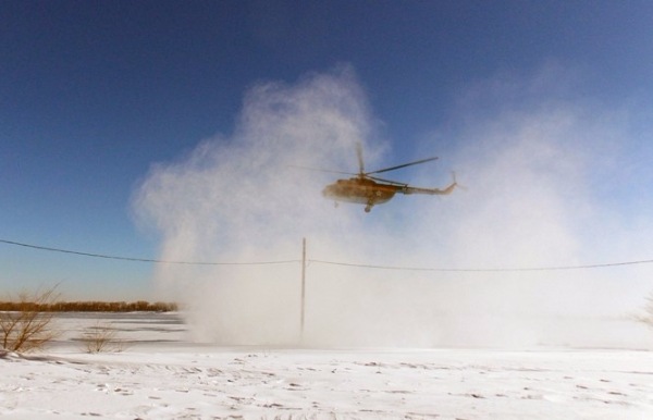
When landing on dry or snowy ground, an air stream from the rotor of the helicopter raises a solid suspension, which critically reduces visibility and can lead to an incorrect assessment by the pilot of the position of the helicopter relative to the ground, in addition, obstacles in the landing zone (large stones, static and moving) can go unnoticed. objects). The term “brownout” describes this phenomenon when landing or taking off on a dry surface. Similar conditions when landing or taking off on a snowy surface are described by the term “white whirlwind” (whiteout).
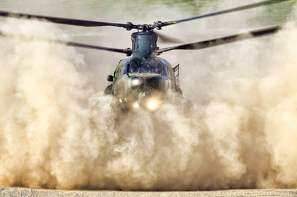
In the review, I will consider solutions in the field of synthetic vision technologies for the safe landing of a helicopter, which allow forming a three-dimensional image of the landing zone through a dusty or snow vortex.
Problem
Solutions
- Synthetic vision
- W band radars
- Lidars
- Development
Problem
Blind landing on unprepared sites causes a significant percentage of accidents.
According to the Canadian Forces, from 1986 to 2006. the snow whirlwind caused two disasters and 54 helicopter crashes.
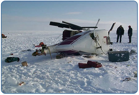
Civil helicopter crash due to a snow whirlwind. Canada, 05.20.2000.
Similar statistics are given for landing on a sandy surface. With the start of NATO operations in the Middle East, a dusty whirlwind caused helicopter crashes in approximately 75% of cases. According to the US Armed Forces from 1990 to 2012. More than 30 special-purpose helicopters were disabled and 60 crew members were killed while landing in a dusty whirlwind in areas with a dry climate (Iraq, Afghanistan). The annual material damage to the US Armed Forces from aircraft accidents when landing helicopters in the UNV is estimated at $ 100 million [1] .

The accident of the helicopter AH-64 US Armed Forces. Iraq, November 2003.
Data on the Armed Forces of the Russian Federation are not made public. According to the Office of the Safety Inspectorate of the Federal Air Transport Agency of the Russian Federation, from 2001 to the first half of 2014. landing events caused 6 accidents and 24 civil helicopter accidents [2] .
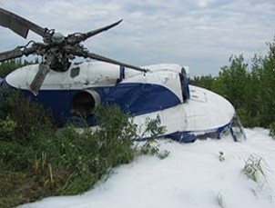
Civil helicopter crash during landing. Russia, Yamal, 02/03/2014.
Helicopter landing at UNV is dangerous because it forces the pilot to rely on his own feelings and on-board navigation devices, data from which is often not enough. However, while still undergoing training, pilots get used to relying mainly on external visual information when landing, independently viewing the selected landing zone for danger. At the same time, they use ground objects as landmarks for controlling the spatial position of the aircraft. This becomes especially important when landing or maneuvering near various obstacles, such as trees, power lines, masts, etc. Due to the instability inherent in all helicopters, which requires extreme concentration during control, pilots must constantly monitor the spatial position of the helicopter.
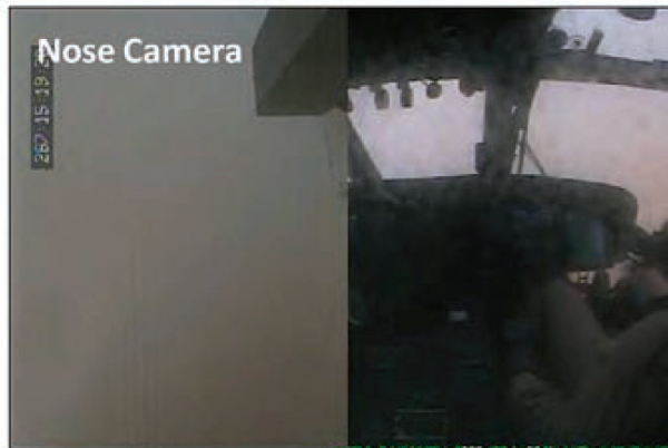
When flying a helicopter in a UNV, clubs of snow or dust do not allow you to see landmark objects with the naked eye. In this regard, the pilot’s dependence on his own vestibular sensations sharply increases. However, under unusual gravitational-inertial conditions, such as in air, information transmitted by the vestibular apparatus and proprioceptors can be misinterpreted by the brain, which leads to additional physical stress on the pilot and can have potentially dangerous consequences.
Dealing with insufficient and (or) conflicting physical sensations, the pilot may experience short-term spatial disorientation. Spatial disorientation in this case is defined as impossibility of perception, or as an incorrect perception of the movement and spatial position of the aircraft relative to a given coordinate system, which is the surface of the earth and the gravitational vertical [3] .
Such disorientation can take various forms: the pilot is not aware of the lateral incline of the helicopter; the pilot creates a false sensation of lateral incline, movement or rotation of the helicopter, although in reality the ship is in a hovering state. The illusion of movement arises due to the circulation of snow / dust outside the cockpit and can occur in all six degrees of freedom of movement of the body, that is, the pilot may feel that the helicopter linearly moves along the Cartesian axes x, y, z (the illusion of linear movement) or rotates around any of three mutually perpendicular axes (yaw, pitch, roll).
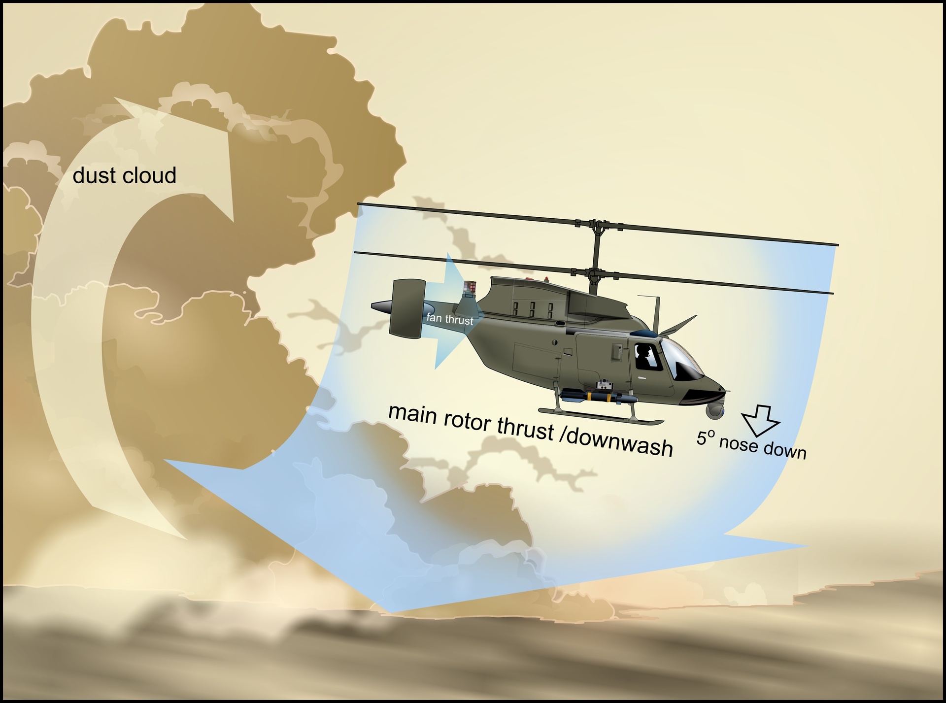
Thus, due to the lack of visual contact with the out-of-doors environment and the insecurity of one's own vestibular sensations, for safe maneuvering (hovering, landing, take-off) in conditions of insufficient visibility, the pilot is forced to rely mainly on the indications of navigation indicators, information from which are received from on-board sensors.
However, the sensors installed on modern helicopters do not provide all the necessary information in difficult weather conditions, as they are not able to effectively scan the landing zone through a sand or snow suspension. In addition, on-board navigation devices do not give an easily readable image, thereby further increasing the load on the pilot. Thus, helicopter crashes during landing in conditions of insufficient visibility lead to false visual-sensory sensations of the pilot and a lack of information from on-board sensors.
When landing on unprepared sites, in addition to overcoming the CNF directly during landing, already at the stage of approaching the landing zone, it becomes necessary to accurately determine the type, topography and characteristics of the underlying surface. For example, when landing on snow-ice ground, you need to know the composition of the soil, the thickness of the snow-ice cover and its density in order to avoid helicopter falling into a snowdrift or under ice. Moreover, roughnesses with a height of 0.5 m or more and surface slopes of more than 15 ° already pose a danger for helicopter landing, especially in strong winds.
So, there are two main causes of accidents:
1. Lack of awareness of the spatial position of the helicopter
2. Lack of awareness of the condition of the landing zone
With regard to awareness of the spatial position of the helicopter, in general, modern on-board navigation devices (GPS, inertial measuring unit, Doppler speed meter, gyroscope, radio altimeter) are able to give all of the above information, but only with good visibility. So, most modern radio altimeters do not work well in a dusty / snow whirlwind and do not display the actual height above ground and the rate of decline.
The situation is even worse with the sensors of the state of the landing zone for viewing through the vortex: existing solutions, such as traditional weather radars, thermal imaging cameras and TV cameras, are not suitable here, and sensors with high penetration are at different stages of technological readiness. We will discuss them further.
Solutions
Technological solutions to the problem of safe landing of a helicopter on an unprepared site in conditions of insufficient visibility are at various stages of readiness, R&D is actively being carried out in the world to create helicopter landing systems, but at the moment there is no commercial solution ready for mass production.
It is important to note once again that any systemic solution to ensure a safe landing should solve two problems:
1. provide situational awareness of the spatial position of the helicopter;
2. Provide situational awareness of the condition of the landing zone.
Such a system should include at least two components:
1. sensors with high penetration for scanning the landing zone in conditions of poor visibility;
2. a display indicator for displaying data from sensors in an intuitive way for the pilot (synthetic vision).
Synthetic vision
Synthetic vision technology involves processing the signal received from the sensors and merging it with pre-loaded surface databases, which ultimately gives a synthetic three-dimensional image of the landing zone. At the moment, synthetic vision systems are at an insufficient technological level of readiness. The main problems of such systems are to ensure that sensors collect relevant information, including landmarks and obstacles, and to display this information in an easily readable form. It depends on the efficiency of processing the obtained data and the reliability of the methods of image fusion, however, neither one nor the other are sufficiently developed technologies.
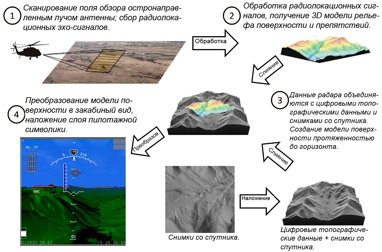
Synthetic vision technology
Currently, the most developed technologies are developed for existing aerobatic applications. In the field of sensors and sensors, these are GPS, an inertial measuring unit, a Doppler speed meter, a gyroscope, a radio altimeter (determine the helicopter’s spatial position), centimeter-range weather radars, TV and IR cameras, laser locators - lidars (determine the state of the landing zone). In the field of indicators, these are traditional aerobatic symbols and helmet-mounted indicator modules (day indicator and night vision indicator glasses).
TV and thermal imaging IR cameras, lidars allow you to view a selected landing zone with a good resolution before the start of a dusty / snow vortex, but their effectiveness in UNV is extremely limited. Centimeter-long weather radars have good penetration, but their disadvantages are low resolution in range due to insufficient broadband of the emitted signals, limited scanning speed due to the use of a mechanical drive in most antennas, and in a too large blind spot due to the use of pulsed signals. All these factors together make meteorological radars unsuitable for determining the condition of the landing zone at short distances, providing sufficient resolution.
The study of the problem of a safe helicopter landing in a dusty / snow whirlwind is receiving great attention in NATO member states, whose armed forces have suffered heavy losses from helicopter accidents and catastrophes during hostilities in the Middle East. Based on NATO technical reports, the most promising areas for solving the problem of landing in a dusty whirlwind are the radar in the millimeter wave range and the laser location. Lidars have a higher spatial resolution than radars, but they are subject to higher attenuation in a dusty vortex. In contrast, millimeter-wave radars have negligible attenuation and provide acceptable spatial resolution.
W band radars
An active millimeter-wave radar with an operating frequency of 77–94 GHz can effectively scan through a dusty vortex. In modern Western models, existing radar technologies are used and adapted, for example, missile homing radars. Radar information is superimposed on the saved surface database, after which a synthetic image of the landing zone with obstacles marked with color is displayed on the display indicator (on-board or helmet-mounted).
The largest number of tests of radar landing systems was conducted in the United States.
Sandblaster - USA
From 2007 to 2009 Under the auspices of DARPA, a Sandblaster system based on a 94 GHz radar was developed and tested. Sikorsky, Honeywell and Sierra Nevada Corporation participated in the development of the system. The helicopter, equipped with a prototype system, made a successful landing in a dusty whirlwind. Tests for wire detection were also conducted, which showed that the Sandblaster dust-penetrating sensor clearly sees power lines [4] .
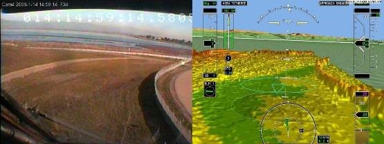

The composition of the system:
- 94 GHz pulse radar (Sierra Nevada Corp.)
- Surface Databases with Terrain and Static Obstacle Information (Honeywell)
- Block for processing and merging radar signals and databases (Honeywell)
- Aerobatic Symbols (Honeywell and Sikorsky)
- Synthetic Vision Indicator (Sikorsky)
- Electro-Remote Flight Control System (Sikorsky)
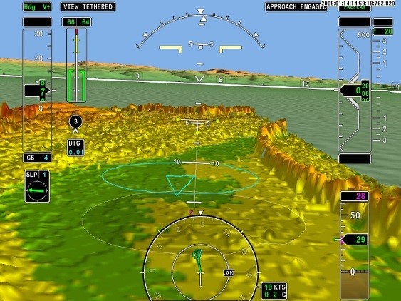
From the report of the pilots who conducted the test of the system: “the resolution of the radar was lower than we would like, and the scanning time for the landing site also turned out to be longer than we would like.”
HALS (Helicopter Autonomous Landing System) - USA
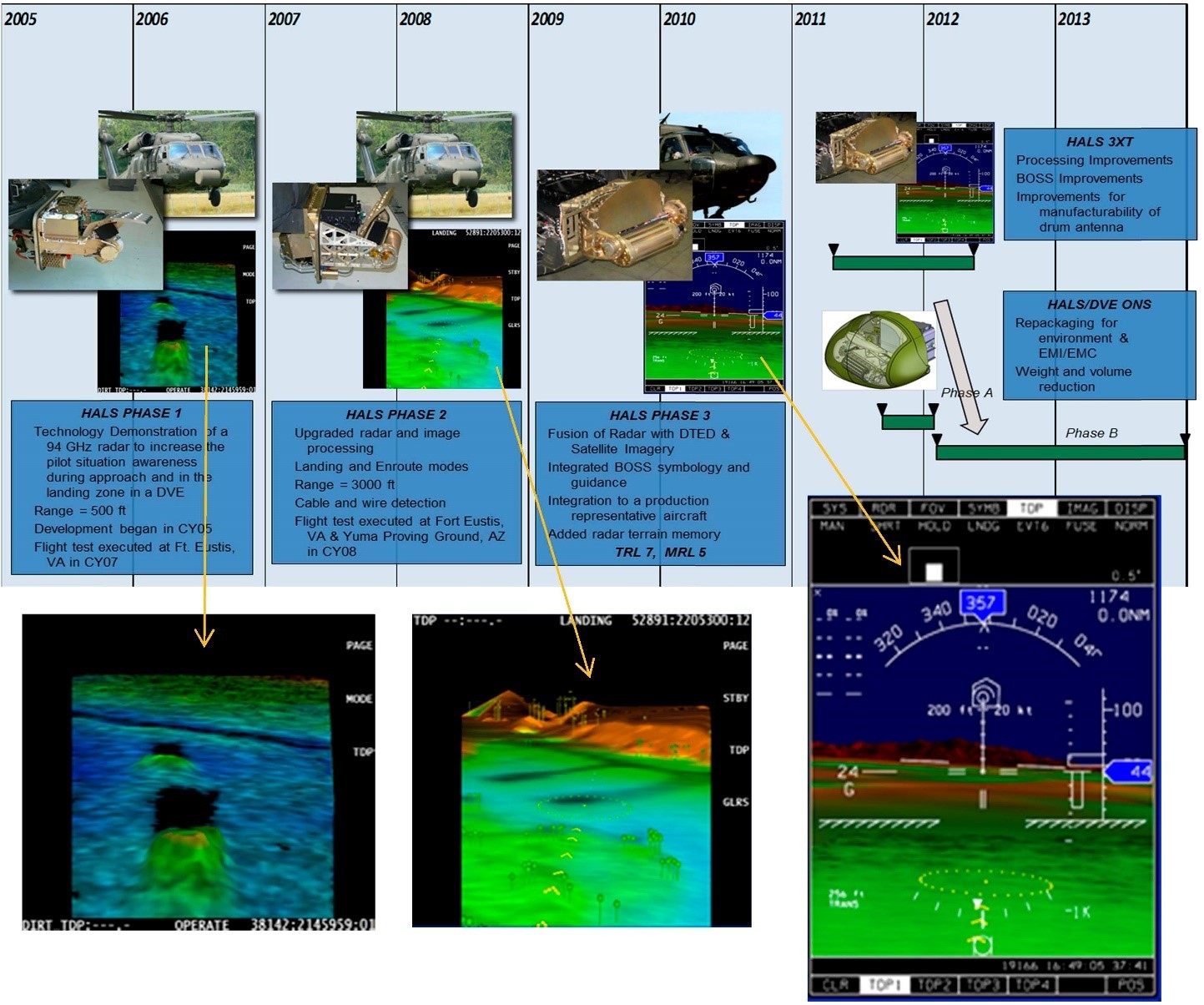
Another landing system based on the W-band radar, HALS (Helicopter Autonomous Landing System), has been developed by Sierra Nevada Corporation (USA) since 2005. At present, the third generation of the HALS-3XT system is presented. Like the Sandblaster system, the HALS-3XT uses a 94 GHz mechanical scan radar. An antenna design with a grid printed on a rotating cylindrical drum maintains an acceptable scanning speed. The spatial resolution of the system scan is 20 cm, the viewing radius is more than 1000 m.
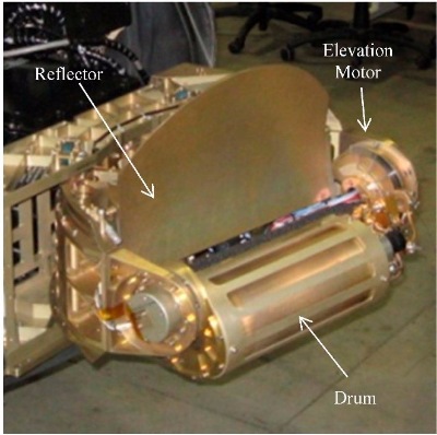
The composition of the system:
- 94 GHz pulse radar
- Antenna with a diffraction grating printed on a rotating cylindrical drum
- Antenna array with electronic scanning (under development)
- Surface Databases
- Block for processing and merging radar signals and databases
- Flight symbolics BOSS (Brownout Symbology System)
It is reported on the development of an antenna array with electronic scanning for the HALS system [5] .
BLAST (Brownout landing aid system) - United Kingdom
BAE Systems BLAST (Brownout landing aid system) manufactured by BAE Systems uses a 94 GHz MBDA Brimstone missile homing radar as a radar.
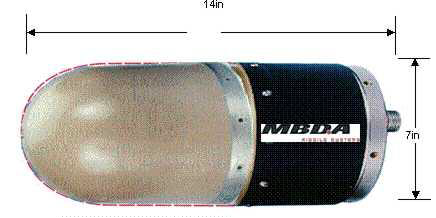
It is reported that the minimum diameter detected by the BLAST system of power transmission wires is 3.2 mm. The manufacturer also reports on the possibility of replacing the main sensor of the system with a lidar or long-wave infrared camera [6] .
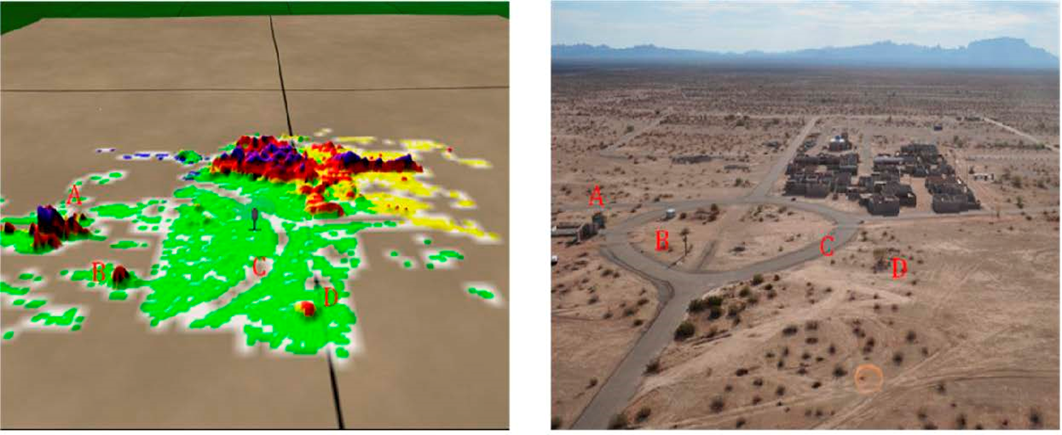
The composition of the system:
- 94 GHz Monopulse Linear Frequency Modulation Radar (FMCW)
- Used MBDA Brimstone missile radar
- Surface Databases
- Control and signal processing unit
- Flight symbolics BOSS (Brownout Symbology System)
Lidars
Laser location technologies are also being actively developed as a means of ensuring a safe helicopter landing. Despite the fact that lidar (including light, laser detection and ranging) has a higher attenuation in a dusty whirlwind, rain and fog than W-band radars, when scanning the landing zone for obstacles, the lidar can provide much higher spatial resolution . Pictures of the landing zone taken by the lidar sensor before the start of the dusty vortex update the dynamic navigation database, after which the image with color-coded obstacles is displayed on the pilot’s indicator. The standard detection range of real targets (terrain, houses, trees) is more than 1000 m, the detection range of wires of an average diameter of 5 mm is 600 m.
In 2009, the US Air Force Research Laboratory tested the 3D-LZ lidar system, a sensor for which was developed by Burns Engineering (USA). Scan resolution was 20 times higher than millimeter-wave radars. Pilots were able to detect objects with a height of 45 cm [7] .
The lidar system DUSPEN (Dust Penetrating System) is developed by Areté Associates (USA) [8] .
Laser locator HELLAS (Helicopter Laser Radar), manufactured by the German concern EADS, is actively used on helicopters of the German police and the US Armed Forces. Currently, the HELLAS lidar has been finalized and is being manufactured by Airbus Defense and Space, a member of the EADS group, as part of the SFERION (Situational awareness system) helicopter safe landing system.
The Raytheon (USA) ADAS (Advanced Distributed Aperture System) system uses optical sensing in the near infrared range, as well as three-dimensional audio notification of the pilot when approaching obstacles.
A comprehensive solution for helicopter piloting in low visibility conditions is the HeliSure system developed by Rockwell Collins (USA).
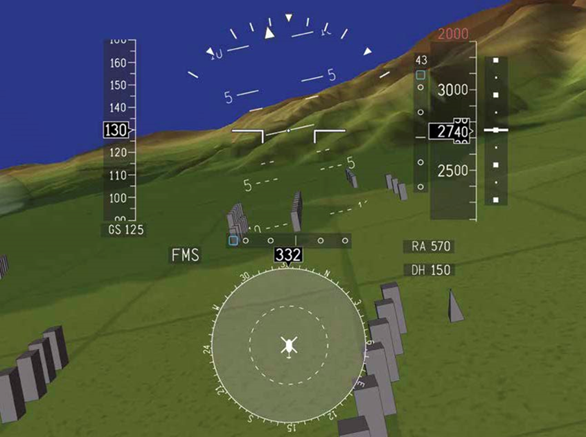
Components HeliSure H-SVS (Helicopter Synthetic Vision System) and H-TAWS (Helicopter Terrain Awareness and Warning System) improve crew situational awareness and allow creating a highly realistic three-dimensional image of the underlying surface and landing zone. However, data on the technology underlying the sensors are not publicly available.
Development
In 2013, the U.S. Department of Defense launched the Degraded Visual Environment Pilotage System (DVEPS) program, which should include the development of an integrated landing system for UNV by 2018. The program includes Boeing, Rockwell Collins, BAE Systems, Sierra Nevada Corp.
In parallel with this, the DARPA agency launched several new projects designed to help solve the problem of a safe landing in UNV (primarily in a dusty whirlwind). In the framework of the DARPA MFRF (Multifunction RF) project, a millimeter-range active phased array antenna (AFAR) is being developed to ensure the landing of military aircraft in the UNV. BAE Systems collaborates with Rockwell Collins, Mustang Technology Group, Honeywell, Applied Signal Intelligence and the University of Michigan.
The AWARE-LS project (Advanced Wide Field-of-View Architectures for Image Reconstruction and Exploitation) is aimed at developing a new generation of image forming sensors (IR cameras, lidars, optical cameras, millimeter-wave radars) and data processing algorithms to create a highly realistic image of the footprint in adverse weather conditions. The project involved Northrop Grumman Corp. and the University of Memphis.
1. “Rotary-Wing Brownout Mitigation: Technologies and Training.” A Technical Report by NATO Research and Technology Organization, North Atlantic Treaty Organization (Jan. 2012).
2. Analysis of the state of flight safety in the civil aviation of the Russian Federation in the first half of 2014. Safety Inspection Office of the Federal Air Transport Agency of the Russian Federation. (Aug. 2014).
3. Robert Cheung. “Spatial Orientation - Nonvisual Spatial Orientation Mechanisms” // F. Previc, W. Ercoline (Eds.) Spatial Disorientation in Aviation. Progress in Astronautics and Aeronautics Volume 203. American Institute of Aeronautics and Astronautics, Inc. Restin, VA, USA. (2004), 37–94.
4. TTPC-AER-TP2-2011 Task outcome report for enhanced / synthetic vision pilotage systems. The Technical Co-operation Program. 2011.
5. Jack Cross; John Schneider and Pete Cariani. "MMW radar enhanced vision systems: the Helicopter Autonomous Landing System (HALS) and Radar-Enhanced Vision System (REVS) are rotary and fixed wing enhanced flight vision systems that enable safe flight operations in degraded visual environments", Proc. SPIE 8737, Degraded Visual Environments: Enhanced, Synthetic, and External Vision Solutions 2013, 87370G (May 16, 2013)
6. Brian Sykora. “BAE systems brownout landing aid system technology (BLAST) system overview and flight test results,” Proc. SPIE 8360, Airborne Intelligence, Surveillance, Reconnaissance (ISR) Systems and Applications IX, 83600M (May 1, 2012).
7. James Savage; Walter Harrington; R. Andrew McKinley; HN Burns; Steven Braddom, et al. 3D-LZ helicopter ladar imaging system, Proc. SPIE 7684, Laser Radar Technology and Applications XV, 768407 (April 29, 2010).
8. James T. Murray; Jason Seely; Jeff Plath; Eric Gotfreson; John Engel, et al. "Dust-Penetrating (DUSPEN)“ see-through ”lidar for helicopter situational awareness in DVE", Proc. SPIE 8737, Degraded Visual Environments: Enhanced, Synthetic, and External Vision Solutions 2013, 87370H (May 16, 2013).