Repair of the Chinese small lamp TrustFire XM-L Z5
Anecdote (instead of an epigraph). The professor gives a lecture to students: ... as you see, this technological solution is simple, understandable, and very reliable. For these reasons, it is not used. In practice, they use another technology, which we will study over the next couple of months ...
This rather expensive flashlight was brought in almost perfect appearance, which indicates its obviously untimely death. And twice dead inside.
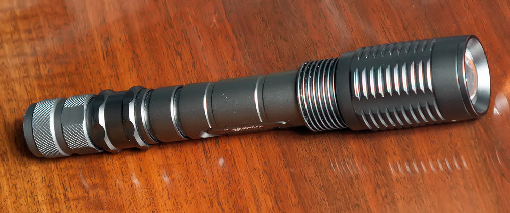
The first time he rested when the electronics of the current driver burned out - it was quite natural for extreme operation at maximum loads. After that, apparently a “craftsman” worked on it, starting up the crystal power directly - as a result, the LED itself also burned out.
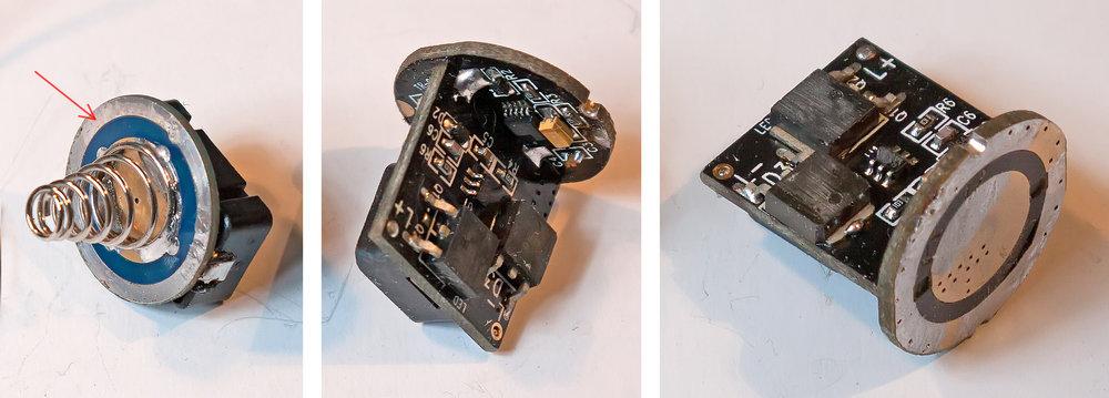
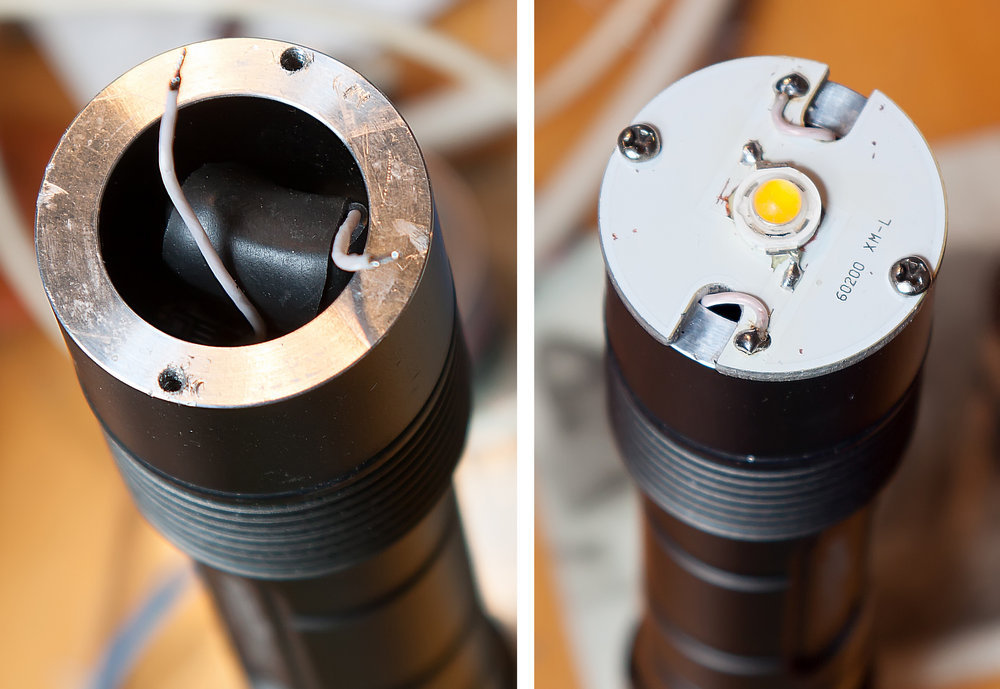
Manufacturers carefully filmed the labeling of transistors and microcircuits, probably out of shame for the suboptimal choice of components. But at the same time, they did not bother to irradiate the copper rims on the circuit board of the switch (on the left, shown by the red arrow), and on the “nickle” of the driver board - which are in contact with the aluminum case. I had to do it myself to prevent the destruction of metals in the resulting galvanic pair. The burnt crystal was dismantled with an industrial hair dryer. Instead, the freshly purchased OS-Star-5W Warm White 3000K 300Lm, rated for 0.7A with a voltage drop of 6v on the LED, was soldered. In the flashlight, it will be used at reduced power, in order to extend the life of the LED and battery life of the flashlight from the battery.
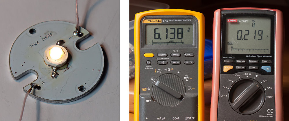
Testing a new crystal. Its heat-removing “dime” also soldered to the substrate to improve heat transfer, but as it turned out later, at the selected operating current 0.2A, the flashlight is practically not heated. A voltmeter (left) shows the voltage drop on the LED connected to the laboratory power supply through a limiting resistor.
Restoring a driver in a confusing and senseless manner, and as shown below, is even harmful in terms of reliability and efficiency in the case of using a flashlight for everyday purposes. Therefore, the nickel was cleared of radio components, and a 10-ohm resistor was used on full batteries to limit the LED current in the 0.2A region.
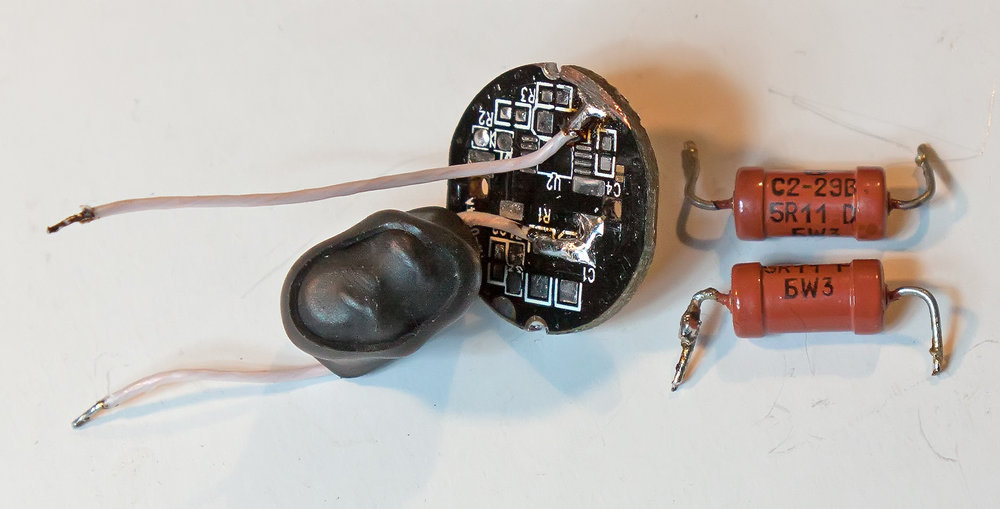
In the photo there are two 5.1 Ohm resistors, similar to those packaged in heat shrink. There they are connected in series there, as a 10 ohm resistor was not at hand.
After flushing with the flux and assembling the LED assembly, the flashlight was put to the test. The 18650 batteries are not “native”, torn from the battery of a laptop that has expired. Nevertheless, some capacity reserve in them still remained. Before starting the run, they were charged to a voltage of 4.12v each.
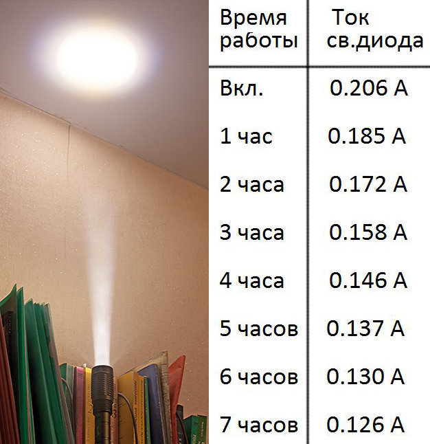
Current consumption was measured every hour. After 7 hours of continuous operation, the battery voltage dropped to 3.6v, which indicates their discharge is not yet final, but it is already close to this. At the same time, a flashlight illuminates the room quite brightly, and on the street it is well visible for more than fifty meters. Thus, the product is restored, and meets the wishes of the customer.
Calculations and rationale
In the original, an LED was used with a voltage drop of 3v on it. The summary table shows the LED current in various modes of operation of the lamp, and the current consumption from the power source. The primary source of information from the forum , and from this review.
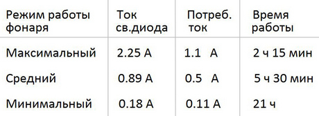
Based on these data, you can calculate the energy saving coefficient of the batteries in the original design of the lamp:
Ke = Icd / Ipit Get
(rounded) for the modes:
These figures show how many times the current consumption from the batteries is lower than the current that would be in the circuit with direct power supply through the limiting resistor. Those. in essence, they characterize the power savings obtained due to the pulsed LED driver power supply.
On the newly installed LED, the voltage drop is already 6v, it constructively consists of two three-volt sections connected in series. And that means the amount of light emitted at the same flowing current, it has twice as much as the original three-volt one.
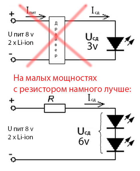
The current consumption of the circuit with a resistor limiter is in the range from 0.21 to 0.13 A, depending on the degree of battery discharge. But taking into account the doubling of the emitted light, the luminous flux even on discharging batteries is noticeably greater than that of the original circuit in the minimum (economical) mode. For the resistor limiter, the current consumed from the batteries and the LED current are the same. But you can calculate the efficiency as the ratio of the power supplied to the SD to the total power consumed by the entire circuit.
So, the efficiency of a highly reliable flashlight with a resistor instead of a pulse driver is 74% on a fully charged battery , and 81% on a discharged one .
To calculate the efficiency in the original design with pulse power, we take the voltage drop across the LED 3.1v, and the LED current does not change as the battery discharges.
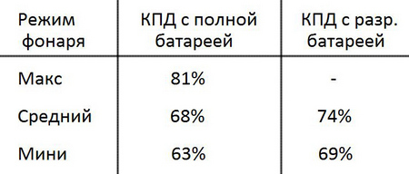
It turns out that at low power for everyday needs - the correct selection of the LED is optimal, and the use of a simple and reliable resistor current limitation. This approach provides greater efficiency in the use of battery energy compared to powering through a pulse driver. As well as a long-term uptime resource, due to the reliability of the circuit, and the fact that in an underloaded mode the LED will last many times longer.
A small explanation The
calculation of the efficiency in the circuit by the driver was made without taking into account the increase in current consumption as the batteries discharge. Therefore, the real efficiency with a pulse generator on the installed batteries will be slightly less than the values indicated in the last table.
With the driver, the LED current is kept constant, and accordingly its brightness. Therefore, as the batteries discharge, the current consumed from them begins to increase. The batteries will run out faster and faster.
With a resistor, the situation is exactly the opposite - the consumption current decreases when the batteries are low, and so on. allows you to stretch one and a half times ... two for about longer than if it were with the driver. Of course, this is achieved at the cost of a slight decrease in brightness, but in such a situation it is better that at least a little light shines than not at all.
Instead of using a resistor, I used the option to use a current stabilizer on an integrated circuit or a field effect transistor, but rejected it as well. reduced battery life compared to the resistor circuit.
The choice of the resistor was due to a reasonable compromise between the minimum required illumination when the batteries are low, and the desire to maximize the battery life. What was achieved - with the batteries installed, the flashlight allows you to read a book text, and gives quite acceptable illumination for orientation on the street, “breaking through” tens of meters.
This rather expensive flashlight was brought in almost perfect appearance, which indicates its obviously untimely death. And twice dead inside.
The first time he rested when the electronics of the current driver burned out - it was quite natural for extreme operation at maximum loads. After that, apparently a “craftsman” worked on it, starting up the crystal power directly - as a result, the LED itself also burned out.
Manufacturers carefully filmed the labeling of transistors and microcircuits, probably out of shame for the suboptimal choice of components. But at the same time, they did not bother to irradiate the copper rims on the circuit board of the switch (on the left, shown by the red arrow), and on the “nickle” of the driver board - which are in contact with the aluminum case. I had to do it myself to prevent the destruction of metals in the resulting galvanic pair. The burnt crystal was dismantled with an industrial hair dryer. Instead, the freshly purchased OS-Star-5W Warm White 3000K 300Lm, rated for 0.7A with a voltage drop of 6v on the LED, was soldered. In the flashlight, it will be used at reduced power, in order to extend the life of the LED and battery life of the flashlight from the battery.
Testing a new crystal. Its heat-removing “dime” also soldered to the substrate to improve heat transfer, but as it turned out later, at the selected operating current 0.2A, the flashlight is practically not heated. A voltmeter (left) shows the voltage drop on the LED connected to the laboratory power supply through a limiting resistor.
Restoring a driver in a confusing and senseless manner, and as shown below, is even harmful in terms of reliability and efficiency in the case of using a flashlight for everyday purposes. Therefore, the nickel was cleared of radio components, and a 10-ohm resistor was used on full batteries to limit the LED current in the 0.2A region.
In the photo there are two 5.1 Ohm resistors, similar to those packaged in heat shrink. There they are connected in series there, as a 10 ohm resistor was not at hand.
After flushing with the flux and assembling the LED assembly, the flashlight was put to the test. The 18650 batteries are not “native”, torn from the battery of a laptop that has expired. Nevertheless, some capacity reserve in them still remained. Before starting the run, they were charged to a voltage of 4.12v each.
Current consumption was measured every hour. After 7 hours of continuous operation, the battery voltage dropped to 3.6v, which indicates their discharge is not yet final, but it is already close to this. At the same time, a flashlight illuminates the room quite brightly, and on the street it is well visible for more than fifty meters. Thus, the product is restored, and meets the wishes of the customer.
Calculations and rationale
In the original, an LED was used with a voltage drop of 3v on it. The summary table shows the LED current in various modes of operation of the lamp, and the current consumption from the power source. The primary source of information from the forum , and from this review.
Based on these data, you can calculate the energy saving coefficient of the batteries in the original design of the lamp:
Ke = Icd / Ipit Get
(rounded) for the modes:
- maximum - 2.05
- average - 1.78
- minimal - 1.63
These figures show how many times the current consumption from the batteries is lower than the current that would be in the circuit with direct power supply through the limiting resistor. Those. in essence, they characterize the power savings obtained due to the pulsed LED driver power supply.
On the newly installed LED, the voltage drop is already 6v, it constructively consists of two three-volt sections connected in series. And that means the amount of light emitted at the same flowing current, it has twice as much as the original three-volt one.
The current consumption of the circuit with a resistor limiter is in the range from 0.21 to 0.13 A, depending on the degree of battery discharge. But taking into account the doubling of the emitted light, the luminous flux even on discharging batteries is noticeably greater than that of the original circuit in the minimum (economical) mode. For the resistor limiter, the current consumed from the batteries and the LED current are the same. But you can calculate the efficiency as the ratio of the power supplied to the SD to the total power consumed by the entire circuit.
So, the efficiency of a highly reliable flashlight with a resistor instead of a pulse driver is 74% on a fully charged battery , and 81% on a discharged one .
To calculate the efficiency in the original design with pulse power, we take the voltage drop across the LED 3.1v, and the LED current does not change as the battery discharges.
It turns out that at low power for everyday needs - the correct selection of the LED is optimal, and the use of a simple and reliable resistor current limitation. This approach provides greater efficiency in the use of battery energy compared to powering through a pulse driver. As well as a long-term uptime resource, due to the reliability of the circuit, and the fact that in an underloaded mode the LED will last many times longer.
A small explanation The
calculation of the efficiency in the circuit by the driver was made without taking into account the increase in current consumption as the batteries discharge. Therefore, the real efficiency with a pulse generator on the installed batteries will be slightly less than the values indicated in the last table.
With the driver, the LED current is kept constant, and accordingly its brightness. Therefore, as the batteries discharge, the current consumed from them begins to increase. The batteries will run out faster and faster.
With a resistor, the situation is exactly the opposite - the consumption current decreases when the batteries are low, and so on. allows you to stretch one and a half times ... two for about longer than if it were with the driver. Of course, this is achieved at the cost of a slight decrease in brightness, but in such a situation it is better that at least a little light shines than not at all.
Instead of using a resistor, I used the option to use a current stabilizer on an integrated circuit or a field effect transistor, but rejected it as well. reduced battery life compared to the resistor circuit.
The choice of the resistor was due to a reasonable compromise between the minimum required illumination when the batteries are low, and the desire to maximize the battery life. What was achieved - with the batteries installed, the flashlight allows you to read a book text, and gives quite acceptable illumination for orientation on the street, “breaking through” tens of meters.